
You are using an out of date browser. It may not display this or other websites correctly.
You should upgrade or use an alternative browser.
You should upgrade or use an alternative browser.
foundingpower programmable bms
- Thread starter nechaus
- Start date

really big thanks guys.
i set it the way you said and after some time of understanding the settings, the BMS is charging and discharging !!
now, i like to share with you something important:
I am so angry after I realized that this BMS is 16 cells, while i ordered and payed to Eason from foundingpower for 24s BMS !
sharing this post here, for people who will know the truth, and choose the right seller for ordering this BMS.
if i knew mucek befor, i wold order the BMS from him, or order it from another honest seller.
not only that Eason lie to me and send me16s BMS instead of 4-24s,
this guy did not answer my many applies to him, sent me a not working software, and keep on ignoring my messages in skype, e-mails, web site messages and aliexpress messages.
for you to know, that i am importing goods from china on a daily base, and working with a lot of sellers. rarely i will find myself writing something like that about a seller, but this guy passed a red line for being dishonest in a bad way. this kind of behavior is something i will never support, and will worn people about.
it took me a long time to understand that this guy is not going to help me to set it right, and with your help i understood that he supply to me the wrong product.
i planed of working with 4-20s li-ion battery (i am a lithium battery assembler and need this BMS for balancing and testing lithium packs), and now i will work with MAX of 16s packs.
here is the first conversation with Eason, you can see clearly that i asked for 24s BMS.
Eason wrote to me: "All my programmable BMS supports 4-24s cells." now we know it's a big lie !
"
Me
22:20 Oct 20,2013
hello
do you have Programmable BMS 12V-72V for 1-24 cells?
thank you
ilan
Eason Lau
22:21 Oct 20,2013
Hello,
All my programmable BMS supports 4-24s cells.
Thanks
Eason
Me
22:36 Oct 20,2013
please send me link
Eason Lau
22:37 Oct 20,2013
please tell me more about your application.(battery info,working current info....)
I have different BMS for different applications.
Me
22:41 Oct 20,2013
battery type: li-ion, lipo, lifepo4
current: 10-80A
Eason Lau
01:16 Oct 22,2013
Hello,I have some good customers in your country,They are familar with my BMS,
Would you please contact with him?
22:43 Oct 20,2013
http://www.aliexpress.com/store/product/Foundingpower-programmable-control-relay-BMS-for-48V-72V-Battery-Management-System/113995_1302170138.html
for control relay application
22:43 Oct 20,2013
http://www.aliexpress.com/store/product/Foundingpower-programmable-BMS-LTC6803-3-Control-Throttle-Battery-Management-System-OLED/113995_1293897688.html
for e-bike application,control key/throttle.
"
with the same passion,
this forum, with the wonderful help of some great people, it the only reason why my BMS is working now. people here sent me the updated software, and support me until the BMS functioning well!
thank you for reading
ilan
Hi there!
I'm sorry for you to have bad experiences with Eason ... Do try to contact him and explain him situation and don't expect him to answer very quick. (don't know how much time ago you sent him mail, but I know he went to HongKong for some bussiness trip)
Though from the links he sent I see, the first link contains 2 different BMSs (16S and 24S) and the second only one (24S) - it's kind a messy description, many pictures from different versions (also non-existed like LCD (now it's OLED used for a while!) ).
Basically, from what I know, there are 2 different versions of BMS avalible (I only support one, 24 S - decided to go for one version), one for 24 S (meant mostly for e-vehicles) and one for 16 S (meant mostly for backup systems). There are/were other BMSs avalible on his webpage (12 S), but as far as I know, those are the only "alive" BMSs.
Regards,
Gregor
p.s. I didn't understand what you mean when you wrote, that you plan to use this BMS for battery analysis ...
I'm sorry for you to have bad experiences with Eason ... Do try to contact him and explain him situation and don't expect him to answer very quick
. (don't know how much time ago you sent him mail, but I know he went to HongKong for some bussiness trip)Though from the links he sent I see, the first link contains 2 different BMSs (16S and 24S) and the second only one (24S) - it's kind a messy description, many pictures from different versions (also non-existed like LCD (now it's OLED used for a while!) ).
Basically, from what I know, there are 2 different versions of BMS avalible (I only support one, 24 S - decided to go for one version), one for 24 S (meant mostly for e-vehicles) and one for 16 S (meant mostly for backup systems). There are/were other BMSs avalible on his webpage (12 S), but as far as I know, those are the only "alive" BMSs.
Regards,
Gregor
p.s. I didn't understand what you mean when you wrote, that you plan to use this BMS for battery analysis ...
Thanks mucek, for you'r softness and understanding.
Eason is not coming back to me for a long long time, so in this point i will let it go and work with what i have in hand.
i am working with this BMS, by connecting it to a lithium packs, and than charge and discharge is for a couple of times, while i am watching the cells behavior on the screen.
by connecting the pack to a different load levels, and checking if it hold the right load that is suppose to, i can say the average time this pack will live, or get to a conclusion for replacing it with a new one.
a part of my work is testing lithium battery packs, and publishing the results, for people to learn.
soon we will get a "cells cycle life tester", and after a few months we will know the truth about the real cycle life for some known lithium cells
thanks for great help
ilan
Ah, I see. I also do cell analysis, but mostly I am using Pulsar 3 (http://www.pp-rc.de/CHARGING-TECHNIC/ACCU-CHARGER/Profi-accucharger-Pulsar-3.htm?shop=pp-rc_en&a=article&ProdNr=1234V&t=3&c=6&p=6 - 1,5 kW in/out) for packs. Unfortunnatly this one is also "only" up to 16S. You might consider buying this one, as this is really a monster! The best on this device is, that it has built in SD card slot, so measurements can be also stored directly (no need for computer as with other chargers/analyzers).
For single cell measurements I am using BK8510 (http://www.bkprecision.com/products/dc-electronic-loads/8510-600-w-programmable-dc-electronic-load.html) electronic load and TTi QPX1200 (http://www.tti-test.com/products-tti/psu/qpx-series.htm) as a charger, both controlled via LAN, so I can use my own software to control both and do the measurments.
Regards,
Gregor
The best on this device is, that it has built in SD card slot, so measurements can be also stored directly (no need for computer as with other chargers/analyzers).For single cell measurements I am using BK8510 (http://www.bkprecision.com/products/dc-electronic-loads/8510-600-w-programmable-dc-electronic-load.html) electronic load and TTi QPX1200 (http://www.tti-test.com/products-tti/psu/qpx-series.htm) as a charger, both controlled via LAN, so I can use my own software to control both and do the measurments.
Regards,
Gregor

thanks for sharing this great knowlage mucek,
this "Profi - accucharger Pulsar 3" looks like a high quality charger.
from reading it's features it look like it can not charge 16s li-ion, is it?
i need it to charge a 16s pack (better do 20s).
for the DC load, when i test a lithium packs, i need to test it on 1-3kw load (mainly for a short time), depend on the capacity and discharge current the BMS and cells should supply.
by searching on the web for this 3kw DC load, i found some highly expensive devices, so i build a device that cost me less than 50$ and works great for me
I converted a 220v - 2000w fan heater to be my DC load (the simple heaters used at home), by connecting to it's coil some on/off switches, so i can control it's resistance.
actually i divided it heating coil to 4 coils, so i can put on load even a 24v battery and load it up to 0.8-1kw.
when connecting a 60v pack, can put it on load of 1.5kw (or more), if use the 4 coils in parallel.
when this device is working, it coil get red hot, so the fan have to work while testing a battery pack.
to keep it simple, i use the same 220v fan that installed in it, not to deal with converting a DC voltage and so.
it is a simple device that works great for a year and so.
if someone here like/need to build one for himself, i will share some photos and knowlage.
thanks
ilan
Hi again!
Pulsar 3 can charge 16S LiPos for sure, but the problem is that top voltage is limited to 64 V (4 V per cell) because of stupid regulations (electronic equipment with voltages bellow 65 VDC require much simpler "papers" for certification). So it's a bit stupid ...
With electronic loads you are right - proper electronic loads cost a large amount of money and you can build own (using bulbs or heater wire) for lots more - and this is more then enough for simple testing. The "problem" I have is that with proper cell measuring (I mean, if I want to provide an official certificate to a client) a professional calibrated load is required. Additionally, if using "simple" resistive load, a current will falling when the voltage will fall as well. But for simple analysis your method is far best and very cheap! (I used it too! )
Perhaps it would be a good idea to build and publish some opensource dummy load with microprocessor (which can also measure voltage and current, control power (also using PWM, so load can be adjusted) and do the capacity etc. calculations) ...
Regards,
Gregor
Pulsar 3 can charge 16S LiPos for sure, but the problem is that top voltage is limited to 64 V (4 V per cell) because of stupid regulations (electronic equipment with voltages bellow 65 VDC require much simpler "papers" for certification). So it's a bit stupid ...
With electronic loads you are right - proper electronic loads cost a large amount of money and you can build own (using bulbs or heater wire) for lots more - and this is more then enough for simple testing. The "problem" I have is that with proper cell measuring (I mean, if I want to provide an official certificate to a client) a professional calibrated load is required. Additionally, if using "simple" resistive load, a current will falling when the voltage will fall as well. But for simple analysis your method is far best and very cheap! (I used it too!
)Perhaps it would be a good idea to build and publish some opensource dummy load with microprocessor (which can also measure voltage and current, control power (also using PWM, so load can be adjusted) and do the capacity etc. calculations) ...
Regards,
Gregor
hello musek (is it actually your name? or just a nick name),
my plan in bulding this charging+load testing device, by using the Smart BMS i have.
need to control it's Amperage lode, and have the rest i need in it software.
after finishing it, i will publish it for people to make there owns.
for knowing what i need to do for this device to work,
have some questions about the Smart BMS please:
1. can i control it's Discharging Amperage load from the software? (i changed the "DCHC OC ... A", but did not effect the load current)
2. how do i measure the AH when discharging? (hope the software can do it)
3. how do i measure the AH when charging? (hope the software can do it)
4. when i pressed "GHG Disable" in disconnected it for a short time, and than back on. same with discharging. any idea?
5. were to purchase a plastic BOX for this 16s BMS?
thank you
ilan
Hi!
Mucek is my nick and in Slovenian language it means "small cat". My real surname is Macek (which means "cat")
As to your questions:
1) You can't control charging current, MOSFETs on BMS only work as a switch (to disconnect the charger if overcharged). For controlling the charging current you should control the charger. See Meanwell RSP-750 (http://www.meanwell.com/webapp/product/search.aspx?prod=RSP-750) .- you can control voltage and current using 0-5 V signals from microcontroller.
2, 3) Yes, you can see capacity on the display and in PC software. However you can't see Ah charged and Ah discharged (only current battery Ah state).
4) No idea what you think. Can you describe a little more?
5) No idea. I also don't know if everything I answered is correct as I only know smartBMS (24S) well ... (and there are differencies for sure, also data protocol is not the same!)
Regards,
Gregor
p.s. Do you know Logview software?
Hi all!
In case that you have problems with screen switching (OLED, display switches without pressing a switch), I'd like to add a solution (wrote about it already): put a ceramic capacitor (100 nF usually does the job, but if there's lots of electric noise also valves 1-10 uF can be used!) between button pins. Additionally, if you need longer cable, do mind that cable must be shielded and shield connected to GND. Just had one such case with electric car, where OLED cable was extended to 4,5 m and display switches, when motor started.
I would also like to inform you, that new batch of smartSMSs arrived and are in stock!
Regards,
Gregor
vodka
100 W
- Joined
- Oct 22, 2009
- Messages
- 121
Hi Folks,
I have bought a LY.FS12Y.BMS quite a while ago. It's probably one of the first versions. This week I decided to give it a go. I followed the instructions to connect a 12s battery to test. First thing I noticed the small LCD didn't show anything, there is no switch for the LCD back light. Second thing I tried was the RS232 Connection that didn't work either, I tried it from two different Computers. The Software says it connected but it doesn't update anything. So my questions are:
Thanks for your help
I have bought a LY.FS12Y.BMS quite a while ago. It's probably one of the first versions. This week I decided to give it a go. I followed the instructions to connect a 12s battery to test. First thing I noticed the small LCD didn't show anything, there is no switch for the LCD back light. Second thing I tried was the RS232 Connection that didn't work either, I tried it from two different Computers. The Software says it connected but it doesn't update anything. So my questions are:
Where does the BMS get the Power from?
Is it sufficient to only connect a 12s battery which only uses the first port to power it up?
Or do I need to have the Charger and 5V Throttle Power from the controller connected to ?
Thanks for your help
Don't know your model, but I guess that:
- connecting battety cells should be enough
- there could be some power pin to enable Bms (I.e. Lock In for smartBMS).
- Software you have may not be compatible. There are few different protocols.
Do you have any documentation?
Regards,
g
- connecting battety cells should be enough
- there could be some power pin to enable Bms (I.e. Lock In for smartBMS).
- Software you have may not be compatible. There are few different protocols.
Do you have any documentation?
Regards,
g
vodka
100 W
- Joined
- Oct 22, 2009
- Messages
- 121
mucek said:Don't know your model, but I guess that:
- connecting battety cells should be enough
- there could be some power pin to enable Bms (I.e. Lock In for smartBMS).
- Software you have may not be compatible. There are few different protocols.
Do you have any documentation?
Hi Mucek, thanks for the reply
i actually use the Software and Hardware that foundingpower (Eason) sent me.
Please have a look how the Power switch is soldered, could that be the fault?
Here is the documentation Eason sent me:
http://s000.tinyupload.com/index.php?file_id=52576157432389551035
Attachments
Huh this really seems to be quite old model - I am not familiar with it and it also doesn't have same (or even similar) PCB as the current model. From what I see, there is 3-pole pin with ON-/-OFF marking on it. I would try my luck here first (middle pin to left/right pin) to connect here first.
So, when you connect your cells, nothing happens (do you have display?), regardless of the on/off switch?
Regards,
Gregor
So, when you connect your cells, nothing happens (do you have display?), regardless of the on/off switch?
Regards,
Gregor
XLR8
100 W
I have one of these BMS's and the ON/OFF switch is a logic switch which works the opposite way to a normal switch. Open turns the BMS ON, closed is OFF. From memory, I think the switch connects ground to an input of N4 which cuts power to the regulator chips. The wires from the switch go to the middle hole of the PCB S4 and the other goes to a resistor near pin 1 of chip N4.
Does anyone know what chip N4 is ? N4 has died on my BMS and I haven't received a reply from Eason regarding this chip.
Does anyone know what chip N4 is ? N4 has died on my BMS and I haven't received a reply from Eason regarding this chip.
vodka
100 W
- Joined
- Oct 22, 2009
- Messages
- 121
mucek said:So, when you connect your cells, nothing happens (do you have display?), regardless of the on/off switch?
Yes, I tried everything.
XLR8 said:Does anyone know what chip N4 is ? N4 has died on my BMS and I haven't received a reply from Eason regarding this chip.
Did your BMS ever work? Can you post some photos of it?
XLR8
100 W
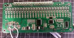
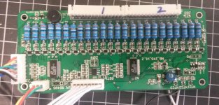
The markings on N4 were MKAE and SAYB . The BMS did work until one day I was tidying up the sense wires and didn't follow the golden rule "check all the voltages of the cells at the plugs before plugging it into the BMS".mucek said:Hmm, can you make good macro photos of both sides of the board as well as N4 with all its markings?
Regards,
Gregor
I bypassed N4 with a suitable DC external supply to the regulator chips and the BMS worked. After replacing some resistors and mosfets, the BMS was balancing all 24 cells. Fortunately, I was able to note the markings on N4 until I tried to make them clearer and managed to obliterate the markings altogether.
View attachment 2
View attachment 1
vodka
100 W
- Joined
- Oct 22, 2009
- Messages
- 121
Ok, i did some testing.
The bms doesn't work in the 12 s Configuration. The Power switch was soldered to the wrong pins. I hooked up a Power supply to the Ground and to the last Pin of the second Battery connector. Then I was able to connect through RS232. However the D52 gets very hot if I do this. And the LCD didn't work. This guy Eason doesn't seem to give a flippin flip. Still no reply after a week!
Could you be more specific please? Seem You got the same board. Can you tell me where the switches for the LCD back light have to be soldered to?
The bms doesn't work in the 12 s Configuration. The Power switch was soldered to the wrong pins. I hooked up a Power supply to the Ground and to the last Pin of the second Battery connector. Then I was able to connect through RS232. However the D52 gets very hot if I do this. And the LCD didn't work. This guy Eason doesn't seem to give a flippin flip. Still no reply after a week!
XLR8 said:After replacing some resistors and mosfets, the BMS was balancing all 24 cells. Fortunately, I was able to note the markings on N4 until I tried to make them clearer and managed to obliterate the markings altogether.
Could you be more specific please? Seem You got the same board. Can you tell me where the switches for the LCD back light have to be soldered to?
XLR8
100 W
vodka said:Ok, i did some testing.
The bms doesn't work in the 12 s Configuration. The Power switch was soldered to the wrong pins. I hooked up a Power supply to the Ground and to the last Pin of the second Battery connector. Then I was able to connect through RS232. However the D52 gets very hot if I do this. And the LCD didn't work. This guy Eason doesn't seem to give a flippin flip. Still no reply after a week!
XLR8 said:After replacing some resistors and mosfets, the BMS was balancing all 24 cells. Fortunately, I was able to note the markings on N4 until I tried to make them clearer and managed to obliterate the markings altogether.
Could you be more specific please? Seem You got the same board. Can you tell me where the switches for the LCD back light have to be soldered to?
I have the very small display which doesn't have any switches to turn it on. Could you try connecting it all up how it should be and with a multimeter, check the input and output voltages of the two regulators N10 and N3 ? They should be 5 volts and 3.3 volts respectively. If there is no input voltage (maybe 6V) to N10 then you may have the same problem as I . Incidentally, you should see the highest cell voltage (up to cell 12) at pin 8 on chip N4.
vodka
100 W
- Joined
- Oct 22, 2009
- Messages
- 121
XLR8 said:I have the very small display which doesn't have any switches to turn it on. Could you try connecting it all up how it should be and with a multimeter, check the input and output voltages of the two regulators N10 and N3 ? They should be 5 volts and 3.3 volts respectively. If there is no input voltage (maybe 6V) to N10 then you may have the same problem as I . Incidentally, you should see the highest cell voltage (up to cell 12) at pin 8 on chip N4.
Cheers for that!
N4 is step down switcher. Power "logic" is to have step down to 6-7 V, then LDO to 5 V and another LDO from 5 to 3V3.
Usually problem is in one resistor (100R) close to it (may be on other side of PCB), which gets burned (should be replaced with 47R!). Other problem I noticed is bad diode on stepdown.
Regards,
Gregor
Usually problem is in one resistor (100R) close to it (may be on other side of PCB), which gets burned (should be replaced with 47R!). Other problem I noticed is bad diode on stepdown.
Regards,
Gregor
Similar threads
- Replies
- 1
- Views
- 772
- Replies
- 2
- Views
- 524
- Replies
- 1
- Views
- 1,546