High-Power LiFePO4 Charger Repair (HP8204L 16S)

amberwolf

Administrator
Staff member
Joined
Aug 17, 2009
Messages
40,824
Location
Phoenix, AZ, USA, Earth, Sol, Local Bubble, Orion
file.php


One of the items donated to the Electricleâ„¢ project is a High-Power LiFePO4 charger for a 48V pack. HP8204L 16S, 58.4VDC 3A. Naturally, like most of the donated things, it's seen better days. ;) This one seems to be a manufacturing problem, though, which could've worked for a while and then blew up. I don't know the circumstances that it's failure were observed under, just that it was not working when donated.

When I opened it up, I found a little burn mark on the bottom next to an obvious modification of the design, but one which appears to have been done at the factory. Two 2-watt-ish power resistors
View attachment 3
have been installed in place of a tiny little SMT part (which is no longer there, so can't tell what it was supposed to be), by:
--heatshrinking whatever these two resistors are (haven't cut the heatshrink to check yet),
--running wires from them thru the high-voltage isolation slot :!: that's pre-cut between sides of a transformer's mounting points on the PCB
--and soldering to pads on the bottom of the PCB somewhere on the secondary side.
Step 2 there is not a brilliant idea, for safety, and is what actually caused the failure, indirectly. One of those wires (neither of which was glued down) got pinched between one of the primary-side transformer pins and the clear plastic sheet that protects the bottom from shorting against the metal charger case. Over time it pushed thru the cheap insulation and POW ZAP KAZOWIE blew something up, dunno on which side of the tranformer yet.
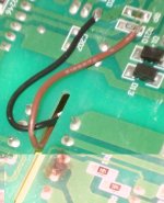
LiFePO4 charger blown wire DSC02765.JPG
I superglued the wires down in the areas near there with no traces, so this can't happen again. I did leave them running thru the isolation slot; if this all works maybe I'll fix that later.

3.5A mains fuse was blown, although since it was wrapped in heatshrink for unknown reasons (there is nothing it could short to even on the endplate) that wasnt' obvious till I started checking with a meter for such things. Since it was a pigtail fuse soldered in, I pulled some fuse holders off an old multifunction laser printer board to install, figuring I'll be popping a few fuses fixing this thing. ;)
LiFePO4 charger blown fuse DSC02768.JPG
Seeing as the holders need two holes but there is only one at each pad for their pigtailed fuse, I had to drill two new holes. I have a handful of little drillbits just for this purpose, but I decided for some reason to hide from myself my Dremel, my hand drill, and my little jewelry screwdriver set that has swappable bits. :roll: No way am I going to be able to spin the little bit between my fingers and make a hole, so a few minutes is spent reinventing a drillbit holder, using the plastic bit of a dog kennel nut as a grip, pushed down onto the threads of an old meter probe tip I had in my box o' test leads.
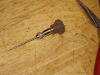
meter lead drill DSC02771.JPG
The probe tip was meant to have replaceable tips, so when they wore out you could put new ones in, and use different sizes for different purposes. But the crappy plastic handle/pencil part of the leads disintegrated long ago, and all I have left is the neat little collet it used. Which happens to have a hole exactly the same size as the drillbit I need to use. :lol:

Now I have a little finger drill I can make holes in the PCB in about a minute or less. Only took me a bit less time to make it than to type this up so far. Installed the fuse holders, and picked a couple of test fuses out of my bag of them salvaged from various power supplies over the years. No 3.5A, but a 2A; should be fine for testing with no load.

Checked some other basic parts for shorts or opens, and seemed ok, so powered it up. POOF. Bright flash inside the fuse glass, which is now totally black except for a little slag on the inside here and there. :roll: Somehow I knew it couldn't be that easy.

I'll have to go back to it later when I can think better to retrace everything on the primary side and find whatever is shorting it so thoroughly. Something sure is, as bad as that fuse blew.
 
Wish I was as smart as you are in your way. Don't want to give up the way I'm smart, (creative inventive) but if I had your kind of smart too I'd be Edison.

You definitely have the key thing I use all the time, the abilty to see when others merely look. Bet you kick ass at where's waldo.
 
Whichever inventor is crazy and wierd, and not really original but endlessly finds strange ways to redo what others already did, well, that's who I'm like. :lol:

Nothing worked out as planned for today, so I sat down with this to trace out power paths and look up parts specs to see what blows the fuse so dramatically, but got distracted even from that by several things. Hopefully have more luck later tonite, or tomorrow before I work.
 
I'm pretty sure that the transformer drive MOSFETs are shorted. It could also have taken out their MOSFET drivers when they failed. You've been doing good work on it!

The light bulb impedance trick might help you from using up a lot of fuses. Place an incandescent bulb in series with the power circuit somewhere. Based on how the circuit is set up it might not work in series with the AC mains. Then it might have to go closer to where the drain of the upper MOSFET is.
 
Hopefully I will correctly troubleshoot it all *before* I have to power it up again, saving all the fuses. :lol:

Looks like it does not use MOSFETs for driving the transformer, but rather transistors. 2x 2SC2625, by Fuji Electric. NPN 400V 10A, 80W, in a TO247 sized case. The primary side pin that wire shorted to is the collector of one and the emitter of the other; they're probably in totempole configuration (I'm still tracing it all out).

That wire's other end goes to those heatshrinked resistors, which then go to the secondary side on the PCB, to the emitter of a TIP127 darlington PNP by STMicro, 100V 5A TO220 case. It's not heatsinked, so it must not be intended to pass much current.

Half of the magic of the charger is a HT46R47 "8-Bit OTP Battery Charger Controller"
http://www.ic-on-line.cn/IOL/datasheet/ht46r47_193829.pdf
It has some appnotes in that datasheet that may help me figure out what everything on here does, but since it is a programmable controller, I can't know all of it without knowing what it has been setup to do.

I can tell you that neither of the pots goes directly to it, so neither adjusts any parameters directly. One goes to a pin on a TL494, which is a "PWM Control Circuit" from TI, designed for controlling power supplies. I guess it's the other half of the magic in the box.
http://focus.ti.com/docs/prod/folders/print/tl494.html
It has two C945 (2sc945) transistors that are probably drivers for the big 2SC2625 transistors (not traced out yet).

And that's as far as I've gotten tonight, with the gunfire a few blocks away disturbing all the dogs everywhere. :(
 
More excellent troubleshooting work. Very professional approach. I am confident that you will solve it and then remodify it correctly, this time overcoming the apparent shortcoming of the last time.
 
Any more info on these chargers?
 
Not yet, at least from me. I just have too many projects. I do need to fix this one, since I need it as a backup for my Vpower pack (which I think is 16s; can't remember). Well, it's sort of adjustable, if I remember where the thread is for that, and determine the limits of this one.
 
V adj is top left per this thread http://www.endless-sphere.com/forums/viewtopic.php?f=14&t=16800

If it's any help, I have the user 'manual' - all 2 pages - with charge curve from my HP8204L3 charger badged as Elite Electronics. It's marked as 36v/3A nominal for 10s and was set at about 41.8V.

EDIT: User manual pages added to the above thread.
 
Thanks--that's the one I think I was remembering--it should help. :)

If there's any way you can scan into a PDF or something, it'd be interesting to see that manual, even if it doesn't directly apply to this one.
 
Back
Top