Portable lightweight 360W LiFePO4 battery charger

avandalen

100 W
Joined
Oct 2, 2010
Messages
175
Location
Maastricht, The Netherlands
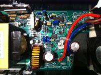
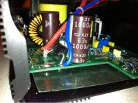
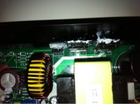
Because I want to fast recharge the LiFePO batteries during a trip, I need a lightweight mobile charger. Special lightweight battery chargers for ebikes don't exist. So I made one myself. I used the battery charger E-400 from BMSbattery in China. I have done modifications to the housing and the electronics.

See my website here:
http://www.avdweb.nl/solar-bike/ele...eight-lifepo4-ebike-battery-charger-800g.html

This is the original E-400 battery charger from 1400g:
EMC-400-LiFePO4-Lithium-Ion-36V-8A-battery-charger.jpg


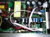
This is the new lightweight battery charger from 815g:
Portable-lightweight-360W-LiFePO4-ebike-battery-charger.JPG


Advantages of the battery charger
  • The weight, inclusive mains cable, is reduced from 1400g to 815g.
    The charge current is adjustable from 1A to 8A instead of a fixed charge current of 8A.
    Integrated anti spark circuit (coming soon…)

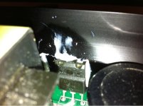
Further weight reducement
In the feature I will reduce the weight to 500g (see website). Who can tell me if my weight reducement assumptions are correct?
 
Very nice work, excellent design goals. A couple of questions:
1. Will this charge work with North American 110V 60Hz AC;
2. Will the voltage be adjustable for SLA, LiFe, and LiPo chemistry?
Cheers!
 
Holocene said:
Very nice work, excellent design goals. A couple of questions:
1. Will this charge work with North American 110V 60Hz AC;
2. Will the voltage be adjustable for SLA, LiFe, and LiPo chemistry?
Cheers!
Hi
The AC Input Voltage is 90Volts~132Volts or 200Volts~264Volts.
Order the E400 charger with the right voltage.
You can adjust any output voltage you need!
So you can use LiFePO4 / Lithium Ion / Lead Acid etc.

Albert
 
I have the 900W version that am going to use for a 30S Lipo bulk charging. I got the 120V version but would like to be able to trim the voltage to better suit. 125V would be preferred. Also like to be able to bulk charge 24S so a voltage of close to 100V would be great also.

There are 7 pots in this charger. Any clue on how I would identify the voltage adjust?

Thanks
 

Attachments

  • P1010044-1.JPG
    P1010044-1.JPG
    88.1 KB · Views: 5,460
Kepler said:
I have the 900W version that am going to use for a 30S Lipo bulk charging. I got the 120V version but would like to be able to trim the voltage to better suit. 125V would be preferred. Also like to be able to bulk charge 24S so a voltage of close to 100V would be great also.

There are 7 pots in this charger. Any clue on how I would identify the voltage adjust?

Thanks
It is a complete different charger. What is the manufacturer? Can you make a larger high resolution image of the whole board? Which SMPS IC is used?
The V pot should be in the Vout feedback loop to the SMPS IC.
Don’t adjust pots when you don’t know what it is.
Albert
 
Thank you so much for sharing your knowledge in such a clear manner. Your website is also fantastic.

Considering that some recently designed power adapters (for example Apple ipod and Macbook) are so small and light, I imagine we could have small, lightweight, powerful and robust chargers if our market were big enough to justify the engineering and production. Maybe someday! Until then it's highly entertaining to follow along with people like you who are creating better solutions on their own.
 
avandalen said:
Kepler said:
I have the 900W version that am going to use for a 30S Lipo bulk charging. I got the 120V version but would like to be able to trim the voltage to better suit. 125V would be preferred. Also like to be able to bulk charge 24S so a voltage of close to 100V would be great also.

There are 7 pots in this charger. Any clue on how I would identify the voltage adjust?

Thanks
It is a complete different charger. What is the manufacturer? Can you make a larger high resolution image of the whole board? Which SMPS IC is used?
The V pot should be in the Vout feedback loop to the SMPS IC.
Don’t adjust pots when you don’t know what it is.
Albert

Thanks for the reply Albert.

I will take some High res photos of the boards. The manufacturer is http://www.emchargers.com I tried to find a schematic but no luck. I know enough about electronics to dangerous but hopefully with a bit of guidance I can identify the V pot.

I certainly wont adjust any pots until I know what they are :)
 
hi albert,

Im planning on buying one of these chargers from BMSbattery, I wanted to ask if the Vout is adjustable? Im running 20s lipo now (~82V for 4.1 per cell) but im planning on switching to 24s in the near future. is it possible to adjust to ~98V output?

thanks mate
sc.
 
sn0wchyld said:
hi albert,

Im planning on buying one of these chargers from BMSbattery, I wanted to ask if the Vout is adjustable? Im running 20s lipo now (~82V for 4.1 per cell) but im planning on switching to 24s in the near future. is it possible to adjust to ~98V output?

thanks mate
sc.
Yes, you can adjust the voltage too. For Higher voltage, order a charger 84V3A / 84V5A etc.
 
Ooops. I made that mistake I orderd a 600w charger but got it initially set to suit my 16s LiFe pack, with the plans to adjust it when I go to a 24s LiFe pack, but it has a 63V cap @ C17 on your schematic. :( Damn.

Can I just swap this cap then make the other mods you outlined? Or am I stuffed?

Regards,
Adrian
 
adrian_sm said:
Ooops. I made that mistake I orderd a 600w charger but got it initially set to suit my 16s LiFe pack, with the plans to adjust it when I go to a 24s LiFe pack, but it has a 63V cap @ C17 on your schematic. :( Damn.

Can I just swap this cap then make the other mods you outlined? Or am I stuffed?

Regards,
Adrian

I suppose that also the SMPS transformer is different, just order a new one to be sure.
 
I was afraid of that. Thanks.
 
avandalen said:
sn0wchyld said:
hi albert,

Im planning on buying one of these chargers from BMSbattery, I wanted to ask if the Vout is adjustable? Im running 20s lipo now (~82V for 4.1 per cell) but im planning on switching to 24s in the near future. is it possible to adjust to ~98V output?

thanks mate
sc.
Yes, you can adjust the voltage too. For Higher voltage, order a charger 84V3A / 84V5A etc.

should I order a 98V model first and then change the Vout down to 82V, that way I know the internal components will be able to handle the 98V when I do end up switching to 24s? Or should I do it the other way around?

cheers.
 
sn0wchyld said:
avandalen said:
sn0wchyld said:
hi albert,

Im planning on buying one of these chargers from BMSbattery, I wanted to ask if the Vout is adjustable? Im running 20s lipo now (~82V for 4.1 per cell) but im planning on switching to 24s in the near future. is it possible to adjust to ~98V output?

thanks mate
sc.
Yes, you can adjust the voltage too. For Higher voltage, order a charger 84V3A / 84V5A etc.

should I order a 98V model first and then change the Vout down to 82V, that way I know the internal components will be able to handle the 98V when I do end up switching to 24s? Or should I do it the other way around?

cheers.
Yes, don't order a charger with too low voltage, to be sure. Adjusting the voltage a lower value is always possible.
 
Are VR1 & VR2 linear (or log) pots?
I'm looking at modifying one for 36V LiFePO4 and low capacity 37V LiIon, and then include for 48V LiFePO4 early next year- probably a 600W one used at 3 - 5 Amps most of the time with the possibility of faster charging if needed.

Thanks.
 
@adrian "Can I just swap this cap then make the other mods you outlined?"

i assume the C17 was the output cap so you should be able to swap to 100V but you need to be sure the schottky diode that keeps the charge in the back end will handle the 24S lifepo4. usually the voltage is stamped on the surface of the schottky diode, and the current rating too. the transformer should work with the higher voltage but you need to adjust the current down to keep the power going through the transformer within the transformer spec, and even below it for continuous output. imo
 
@dnmum

Thanks a lot. I was pretty annoyed when I realised, and haven't even touched the charger since. Now I will crack it open and have a look see. Cheers.
 
I have the 600w model and the board is a bit different. It appears to have two caps (C17 & C18) on the output. But I need to remove the board from the case to check properly.

The shottky diode is labelled as 6A10 MIC, so should be fine. So I guess I just have to swap out the caps, and tweak the current/voltage with the POTs.
 

Attachments

  • charger_600w_pic1.jpg
    charger_600w_pic1.jpg
    149.2 KB · Views: 4,694
  • charger_600w_pic2.jpg
    charger_600w_pic2.jpg
    49.4 KB · Views: 4,694
that black diode is a zener on the output to protect it from reverse polarity. it protects the caps on the output.

the schottky diode will be connected to the output of the transformer, usually two outside legs connected to the same trace and the middle leg going to the output, where that cap is. maybe someone else has opened this power supply too and knows.
 
Kepler said:
I have the 900W version that am going to use for a 30S Lipo bulk charging. I got the 120V version but would like to be able to trim the voltage to better suit. 125V would be preferred. Also like to be able to bulk charge 24S so a voltage of close to 100V would be great also.

There are 7 pots in this charger. Any clue on how I would identify the voltage adjust?

Thanks

hey kepler, I just got the exact same one as you, I need to ask though, does yours have a voltage output once everything is turned on? Mine doesn't, even though the display shows 100V, which makes me worried that something is stuffed, and makes finding which wire is + and - near impossible. Im hoping its just some sort of protection circuit, though im not betting on it...
 
dnmun said:
that black diode is a zener on the output to protect it from reverse polarity. it protects the caps on the output.

the schottky diode will be connected to the output of the transformer, usually two outside legs connected to the same trace and the middle leg going to the output, where that cap is. maybe someone else has opened this power supply too and knows.

Okay thanks. Take 2. I found D15 & D16 which are heatsinked directly to the charger shell, appear to be between the transformer, and L2. They are FMG36S's.
 

Attachments

  • charger_600w_pic3.jpg
    charger_600w_pic3.jpg
    35.8 KB · Views: 4,681
  • charger_600w_pic4.jpg
    charger_600w_pic4.jpg
    34 KB · Views: 4,681
looks good, did you google the specs? those diodes need to be able withstand a higher voltage than your output voltage. and a little bit more, but if they are adequate you can get away with just upping the output caps. they get hot so that's why they get heat sinked to the case. really hot.
 
Back
Top