Modding Dell 12v 700w NPS-700AB

icecube57

10 MW
Joined
Apr 25, 2008
Messages
3,072
Location
Austell GA
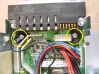
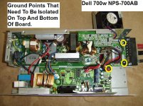
This first picture shows which screws need to be isolated from the case to float the dc ground. You can use nylon washers or fiberboard. I personally used shrink wrap with a whole punched through.
STA70935.JPG
STA70938.JPG
View attachment 2
STA70915 (Medium).JPG
 

Attachments

  • STA70935.JPG
    STA70935.JPG
    77.1 KB · Views: 5,970
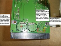
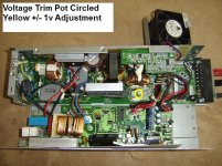
Here is the sister model to the NPS-700ab. Same exact spects but totally different board configuration . If you just one stout ass power supply I think this is a better choice do to the simple fact to where you can attach the output leads. The ground isolation works until you put the top half of the case I would like someone to advise on what im missing.
 

Attachments

  • STA70909.JPG
    STA70909.JPG
    72.5 KB · Views: 5,966
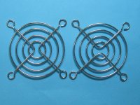
You need to get these if you dont want you finger chopped off at high speed. Although if you do the fan mod it should be spinning much much slower until the power supply is really loaded then yeah it will be a danger.
http://www.ebay.com/itm/2-pcs-DC-Fan-Grill-Protector-Silver-Finger-Guard-Used-for-60mmx60mm-Fan-/261011883963?pt=US_Computer_Fan_Grills_Filters&hash=item3cc58547bb
 

Attachments

  • $(KGrHqZ,!jYE9Hsu1,QqBPmge6v2Y!~~60_57.jpg
    $(KGrHqZ,!jYE9Hsu1,QqBPmge6v2Y!~~60_57.jpg
    254.4 KB · Views: 5,959
Thanks IC57! I guess there is no through plating in those holes? :shock: I may try to get two for my charger. It looks like even I could do that stuff.
otherDoc
 
http://www.flickr.com/photos/liquoredonlife/sets/72157626407615538/detail/

Someone wrote another tutorial with more pics but they didnt isolate it.
 
Im still pulling max current for these for several hours. Ice cold without much sag. Someone should be getting on these. Neptronix cough... cough.
 
icecube57 said:
Im still pulling max current for these for several hours. Ice cold without much sag. Someone should be getting on these. Neptronix cough... cough.

Ha ha, thanks for the pics.
Power supply sales are going at a glacial pace right now and i've got a closet full of HP power supplies to offload. But thanks for the tips.
 
I have a better method for switching these on... It involves bending 1 pin and HDD jumpers.
 
I know this post is super old, but I had to at least give this a try.
In the "isolation" step there are 3 screws that need to be adjusted. For the two without the ground wire I simply put nylon washers on each side of the circuit board, but for the screw with the ground wire, I struggled. I wasn't sure if the ground wire needed to attach to the circuit board or not. In your image it looks like the screw it touching the wire, which then touches the case when you put the screw into the post. When I did that, the case became grounded to the circuit board. I ended up using a nylon screw, with a single nylon washer underneath the board. Doing this the black wire made contact with the circuit board, but was isolated from the case. Can anyone confirm the correct way to do this?
As an FYI, the power supply worked fine, and there was infinite resistance between the case and the negative side of the output.
 
As long as the case is not electrically connected to the board inside, then it is correct.

The main thing you want to do is ensure the DC side of things is completely isolated from the AC side of things, so that if you need to series these you aren't shorting across everything but the most-positive unit.

Since the AC side of the system is probably grounded to teh case for safety, then as long as the DC side is not connected to the same ground, that generally fixes the problem.

If possible, you still want the AC ground connected to the case, for safety, so that there are no floating voltages present on the case that could kill you if you touch it and are yourself grounded somewhere.
 
Back
Top