Making a CC/CV charger

Tiberius

10 kW
Joined
Jan 14, 2008
Messages
871
Location
Rural England
I am indebted to Jeremy and others for their work in this thread http://www.endless-sphere.com/forums/viewtopic.php?f=14&t=4125 where some low cost PSUs were discovered and re-engineered.

Unfortunately these do not have a constant current mode (CC) only a constant voltage (CV). In order to make them useful as battery chargers they need a current limiting circuit. (Note. Read on down the thread: Much later I discover there is a CC mode but it needs adjusting.)

One way is to run them in CV mode and put some kind of current control system in series, but that ends up dissipating a lot of heat, which sort of defeats the object of using a switched mode PSU in the first.

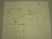
A better method is to find a way of turning the PSU output voltage down to just the right level that gives the desired charging current, and this turns out to be very simple. All these PSUs have a feedback loop to set the output voltage. If you inject a few mA into the right node in this loop, it will adjust the voltage to try to compensate. In the case of PSUs based around the TL494, the feedback node is pin 1 of the TL494.

Here's a simple circuit:View attachment CClimiter.JPG

As soon as the current through the sense resistor is enough to create 0.6 V the voltage starts to turn down. The only high Wattage component needed is the sense resistor - I used a load of 0.5 R's in parallel. The two 4K7s are not in theory necessary, but provide protection in case the transistor fails; I used one at each end of the wire to avoid EMC/EMI problems. It is also useful to have an indication of when the charger switches from CC to CV mode - in this case I reckoned a $5 ammeter was better than a few LEDs.

Here's the finished result:View attachment Charger755.jpg

Two sets of Andersons. Black/Red is the CV output, black/orange is the CC/CV output.
This particular one is set up for 9A/29V to charge 8s LiFePO4.

Nick

YMMV, do it at your own risk, etc, etc. There is a danger of making the PSU unstable so check it under a range of loads.
 
That's cool.

If you wanted to avoid the voltage drop in the sensing resistor, you could use one of those Allegro hall current sensors. You could also use an op amp with a lower resistance shunt.

Is the TL494 on the secondary side?

Virtually all switching mode power supplies use an optocoupler for feedback. You may be able to tie a similar circuit into the input of the opto coupler.
 
I did wonder about a Hall sensor and a little coil of wire. Maybe I'll try that one day. I haven't seen the devices you refer to but I assume that's what they do.

The TL494 is on the output/secondary side in this case. I imagine PSUs that use a different IC still have to have a similar voltage sensing circuit that can be also be fooled.

Nick
 
Looks good. Thanks.

It would need a 5V supply and some interfacing of the output. So its a trade off between the power dissipation and the complexity. If I were laying out a PCB the Hall sensor route is def the way to go, but for <10A and breadboard construction there's an argument for simplicity.

Nick
 
If you want to be cheap and not deal with a separate supply to run an op amp or current sensor, yet still reduce the heating on the sensing resistor, you might be able to offset the transistor's vbe by using a diode. If you choose the diode that has just slightly less voltage drop than the voltage needed to turn on the transistor, you could us a much lower resistance for the sensing resistor.

Just wild guessing, the shunt resistor might be 0.01 ohms and R3 might be 10K
SMPS current limiter 1.jpg

If the diode drop is a bit more than what it takes to turn on the transistor, you could put a divider across the diode and make the limit adjustable with a trim pot.
SMPS current limiter 2.jpg
 
Hey guys, that's a nice subject! :D

When Justin came in Quebec, he toke few hours to help me to limit the current of my 48V 32A monster PSU.

We finally used a LM358 op-amp , a 0.01ohm shunt and a couple of resistors as voltage divider and reference.

Pretty simple circuit and it worked great.. maybe just a littke feedback problem that we solved with a capacitor on the feedback loop. The output was connected on the trim pin input with a resistor in serie. acting on the trim to re-scale the voltage to get the current that allow the current limit active is a great idea

That circuit eliminated the PSU to go in overload protection mode when conecting it on discharged battery.

it also can be used on some DC-DC converter too

Your idea with the transistor is nice too... and to affect the opto output of the psu.

we used the AUX 12V output o fthe PSU to supply the op amp.. it was referenced to the same ground.

here is the original.. "not final" schematics..

Doc
 

Attachments

  • P1060986_1024x768.jpg
    P1060986_1024x768.jpg
    62.9 KB · Views: 4,636
Right, your schematic looks like the "normal" way to do it and it will work nicely.

The problem is most op amps are limited in supply voltage and it would be nice to not need a separate regulator for it.

Doc, what did you tie into on your PSU?
 
fechter said:
Right, your schematic looks like the "normal" way to do it and it will work nicely.

The problem is most op amps are limited in supply voltage and it would be nice to not need a separate regulator for it.

Doc, what did you tie into on your PSU?

If i understand correctly what mean "tie", i would say i used the trim input referenced to the ground controled by the circuit i've shown.

But i had some trouble with hit when i busted the OVP on it... I explain: On my ebike i have a serie/parallel switch to operate at 50V 46Ah or 100V 23Ah. Useally when i charge i put the switch to 50V and charge the two serie pairof battery pack in serie (6s18p+6s18p) parallel to (6s18p+6s18p).

But that time i forgot to put the switch to 50V.. and i've sent 88V (discharged battery) into the power supply :? ..

and it died... no blow, no smells.. no flash.. it just shutted down... I unplugged it and plugped it back to the AC and it won't to power up.. the fan just turn for 1sec and stop... like if it could be a protection mode that stick enabled.. impossible to recover... The output diodes seems to be ok and the output caps too.. i can put external 48V to the output using another power supply and the current is only few miliamp.. so the output is not shorted..

The actual OVP on this RSP-1500-48 power supply is max at 67.5V... a couple of volt lower...

I know that usually, they have a SCR that act as crowbar to maintain the voltage under a desired value.. but this one seems to have none..

Justin and me checked to repair it without any succes.. so i sent it for repair to a local TV repair shop..

Believe me.. next time i'll put a diode in serie and a MOV in patallel and a fuse in serie... it will be buletproof!

Doc
 
fechter said:
If you want to be cheap and not deal with a separate supply to run an op amp or current sensor, yet still reduce the heating on the sensing resistor, you might be able to offset the transistor's vbe by using a diode. If you choose the diode that has just slightly less voltage drop than the voltage needed to turn on the transistor, you could us a much lower resistance for the sensing resistor.

Just wild guessing, the shunt resistor might be 0.01 ohms and R3 might be 10K
View attachment 1

If the diode drop is a bit more than what it takes to turn on the transistor, you could put a divider across the diode and make the limit adjustable with a trim pot.

Hi fechter,

I'd be a bit worried about the first circuit. It might start turning down the volts at zero current, unless you use a Schottky diode, but the second one should work.

Nick
 
Tiberius said:
Hi fechter,

I'd be a bit worried about the first circuit. It might start turning down the volts at zero current, unless you use a Schottky diode, but the second one should work.

Nick

Yes, exactly right. From datasheets for prospective diodes, you should be able to determine the voltage drop at the operating condition. You need to make sure it is less than the voltage needed to turn on the transistor. Most schottky diodes would do this. Even an old school germanium diode should work here.

The adjustable version would make it much easier to trim than having to mess with the shunt resistance.

Doc,
Many OVP circuits just use a zener diode to pull up on a resistor somewhere. You may have blown the zener. Most of the ones I've seen would be small orange glass packages. You can locate anything that remotely resembles a zener and put your meter in diode check mode across them to look for a shorted one.
 
Doctorbass said:
... But that time i forgot to put the switch to 50V.. and i've sent 88V (discharged battery) into the power supply :? .. and it died... ...Doc


Lol, I did the exact same thing with my expensive lipo balance charger. I was breaking my packs down from 24S2P to 6S8P for charging and forgot once! That charger is now in the spare parts pile and I have to charge all my small lipo packs with my old non-balancing charger.

Now I have a convention:

Andersen 75A connectors for anything high voltage (100V)
Deans connectors for any thing up to 25V (6S)

-methods
 
Gentlemen,

Bad form, I suspect, replying to one's own post, but here's an update on this mod.

I found that with some loads there is an instability. On the bench, with an electronic load, it behaves. But at a certain state of charge with a certain size of battery I found it buzzing and oscillating around the operating point. The solution is to slow down the CC loop so that its at a very different speed to the switch mode control loop inside the PSU. All that's needed is to fit a 10 uF cap as shown in either circuit below. The cap only sees a few volts so it doesn't have to be rated for the full output.

CChack2.gif

Nick
 
Now, some further news on current limiting with these PSUs. Although they go into hiccup and shut down mode if you try to use them as battery chargers, it turns out that they do have internal current limiting.

Here's a general view, which may also help to answer the question about whether they are the same as the Meanwell ones or not.
This is a 36 V one - click for larger picture.
PSUgenview1.jpg

The arrow points to the shunt resistor. It comes with two of these shunts fitted and each one is worth 6.5 A.
With an electronic load you can bring the current up slowly and see what happens. With two shunts in it will limit at 13 A and not go into hiccup mode. That looks promising, but about 5 minutes later the PSU will blow up because it can't take that load forever.

Remove one shunt (just cut it) and the PSU limits nicely at 6.5 A and it will take this all day long. So that makes a nice 6.5 A battery charger.
I modified one shunt by soldering a wire to partially bridge it, so as to make the PSU limit at 10 A. It will run this all day long too, provided it has ventilation. I've used this to charge batteries with no problem.

Going back to the picture in the OP, with the panel meter and two output connections. I've now got this set up so that the PSU internal current limit is 10 A and the external circuit turns it down to 5 A. So one output delivers 10 A and the other 5 A and I choose which one to plug into according to what the battery pack will take.

Nick

YMMV, do at own risk, etc.
 
And now, for completeness, some notes on adjusting the voltage.

These PSUs come with a small pot that will give +/-10% adjustment. I'm not sure how much the circuit varies between the 24 V, 36 V, and 48 V versions; I suspect its similar but I've only worked on the 36 V ones.

First, as Jeremy relates in http://www.endless-sphere.com/forums/viewtopic.php?f=14&t=4125 there is an overvoltage protection circuit that cuts in at about 40 V. Find ZD1 under the main transformer. Its a 39 V zener diode. Either replace it with a higher voltage one, or add another one in series. I added a 9V1 zener which takes the limit up to 49 or 50 V.

Secondly, it is possible to move the output voltage to a different level, but why not just increase the range?
R25 next to the pot is 3K9 - change it to 2k2
The pot is 1 K - change it to a 5 K 10 turn. If you get the right model it will fit the PCB nicely.

PSUtrimpot1.jpg

This will now adjust from 22.7 to 49.4 V - call it 23 to 49 V. That means it can be set for 8S to 12S of either Li-Ion or LiFePO4.

Nick
 
Thanks for all the info and mods on these psus :)

Im a electronics newbie but Im gonna give this a try anyway

I need a 12V pb and lifepo4 charger and found the 13,5V/25A version on ebay for 40$ free shipping that would work without the voltage mods.

If these also got two shunt resistors all I would have to do is cut one and I would get around 15A stable output.
Could you describe how to partially bridge the shunt resistor to limit the output to the rated current?
 
thomas said:
If these also got two shunt resistors all I would have to do is cut one and I would get around 15A stable output.
Could you describe how to partially bridge the shunt resistor to limit the output to the rated current?

Hi Thomas,

Like this....
PSUshunt10A.jpg

The 36 V power supplies have 2 shunts. I think Mike (mwkeefer) said the 24 V ones have 3. I suspect the 12 V ones probably have 4 or 5.
To lower the current it limits at, just cut a shunt (don't say that quickly). If you go too far then the current can be raised by partially bridging a shunt. The arrangement in the picture changes it from 6.5 A to 10 A.

Don't completely bridge the shunt, or the PSU will blow up.

Where did you see them advertised? Can you post a link or pm me?

Nick
 
Okay thanks for the help. Bought two of them so got one to experiment on :)

http://stores.shop.ebay.co.uk/ALLEPARTS__W0QQ_armrsZ1QQ_fsubZ1026664012
 
Thanks Thomas,

That seller is providing more info than the other one. It says the PSUs have a current limiting mode, but its for overload protection. What we've discovered is that its set too high for continuous use and needs adjusting down a bit for battery charging.

Nick
 
yes 105-130% overload of rated output.

The 13.5V version probably got 4 shunts so cutting 1 will hopefully work.
Ill leave a post about it once I get them.
 
Hey all,

First Nick... I did some more comparing the PCBS are identical electrically between the various versions... and yes, lower voltages and higher currents are acheived via multiple parallel shunts, since the actual output of my 14.6A before hiccup mode hits is 18.2A (measured) at 20.7v calibration. On this board the 24v 14.6A rated unit there are three shunts with space for 2 more on the board - The 12v units have 4 shunts and the 5v has all 5 shunts.

Removing a single shunt dropped this output down to 12.5 A...

Notice your supply contains SVR2 location but it's not configurable... I have seen yet another supply with the same PCB (I think it was SP-350-24) which has these populated and boasts variable current output +- 20% so... populating these parts correctly and adding small relay (drive off the 12v tap) to switch modes (disable/enable shunts) combined with the svr2 current limiting circuit and a few cap upgrades to 100v (output) + a few modified resistors would provide the most useable supply.

The only issue in overvolting or changing the range to between 12 and 85v is to be sure the output power doesn't cause too much current through the transformer - 400w I think is the max.

Hope this helps... I'm still trying for stable operation in 2 modes with a 3x adjustment range over stock.

-Mike
 
Nick,

Your unit is the 36v correct? with 2 shunts. Mine is 24v with three shunts in what appear to be parallel configuration - I have a 48 and a 12 volt unit @ 350 on order (samples) but also a few of the 145/150w supplies. I have inquired with the manufacturer (yes not the distributor) to get the proper values for the various configuration circuits - ie: resistor values, shunt resistance, pot values, etc ... which allow them to build various outputs on the same PCB (the vendor actually put me in touch with the manufacturer) - I have not yet received a response but if I am correct we have identified the various components and their parts.

Based upon my current research, the 48v unit looks to be the very best for modification as a charger since it's got 63v caps already and can be made to vary from about 12v to 63+ without changing caps, just by adding resistors.... shunts on the 48 will be just 1 though so... we will need to either add multiple shunts which are isolated via relay or switching transistor of appropriate voltage level or we could use a variable solid state resistor to permit for much finer control via a 0 - 5v input (LM317 with regulator between 0 and 5v with pot to adjust) or via analog output channel from MCU.

What I propose is that we enumerate all the possible resistor, caps, shunts and so on for each various model stock - then we source the required parts for the modifications and offer the firmware for the atmel mcu I have used to tie all this together and interface to the PC for current display and voltage... also allows for decent logging and such.

Once we have the complete accurate list of parts to replace to change the "gears" we can then standardize the upgrades for variable CC and variable CV (with greatly extended range).

I will be happy to document and produce proper PCBs for Current Limiting, Gear changing or variable range and a safety circuit to ensure the Max Watts of the transformer aren't exceeded.

-Mike
 
Hello again,

Shunts confirmed via email from other owners, here's the breakdown:

5v unit = 5 shunts { 2.1 ohms / 5 = .42 ohms } = 420 milliohms
12v unit = 4 shunts { 2.1 ohms / 4 = .525 ohms } = 525 milliohms
24v unit = 3 shunts { 2.1 ohms / 3 = .7 ohms } = 700 = milliohms
36v unit = 2 shunts { 2.1 ohms / 2 = 1.05 ohms } = 1.05 ohms
48v unit = 1 shunt = 2.1 ohms

Hope this helps,

Regards

-Mike
 
I have a newb question:

Will this power supply act as a stand alone charger for the Konions in my Bosch 36 volt batteries since they dont need balancing as much as Lipo?
 
etard,

Assuming
1.) You can get or configure a unit to output proper maximum voltage (high voltage cutout)
2.) One of these supplies will not provide too much charging current (take watts, divide by empty pack voltage... that's the amps you will have at beginning of charge for current output. divide watts again by maximum voltage and that is the current that is available at that voltage but it should have tapered to CV by then and the current should be dropping.

Basically... these are just "dumb" power supplies and I don't know enough about the curve your cells want to see.

-Mike
 
Back
Top