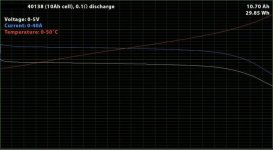
Discharge Curve: Headway 38120S (screw terminal) 10ah cell

oatnet

1 MW
Joined
Apr 26, 2007
Messages
2,361
Location
SoCal, USA
I bought 16 of these cells from Chad (c-hessman) locally, he is now selling them here: http://endless-sphere.com/forums/viewtopic.php?f=9&t=7533

I was told that they are the new headway cylindrical cells, 5c continous, 10c burst. Packaging is blue transparent plastic/vinyl? over metal tube and serial number. I was skeptical of the screw-type ends before I bought, but now I really like them and prefer them over older bolts, should make cell-replacement a snap.

I discharged a cell on my CBA-II, and got this curve hot from a voltfreaks single-cell (3.73v) charger. I'll graph more discharges at 2c and 3c then layer them over this curve, but a full 5c test will exceed the wattage the CBA-II handles. Someone reported they sent a few cells to Doc, whose sophisticated setup will give much more robust data and better detail.
Start temp was @26c (if I remember correctly), end temp 31.1c. I got 9.2ah because I stopped the discharge early at 2.6v to protect the cell, I am sure I would have gotten the full 10ah if I took it all the way down to 2.0v. I'll feel like pulling 8ah duty cycles will represent an 80% DOD that will preserve the cells, plus they will probably get a little stronger as a few dozen cycles wakes up the chemistry.

-JD
View attachment 38120 hh23 12334.JPG
PS: Not sure why this attachment isn't showing up as a picture!
 
Defenitely 10 ah maybe 11 ah. From the graph, it looks pretty good. It really starts to drop at 6ah or so not bad. Could you show us a 2C discharge? I got a couple of batteries going to Doctorbass and if you know him... hes going all the way down to 2V and testing at 10 to 20C :mrgreen: .
 
Be nice to see how these newer headways compare to a PSI cell. I would have thought at 1C it would have been a more flat curve. Looks like it will barley make 10 ah at 1C (which is ok if hats the spec).
 
I've got to agree with pgt400 about the not-so flat curve of this cell (only at 1C) being a bit worrysome. Maybe some breaking in of the cell might help it a bit?

To compare, here is a discharge curve for my Ping V2 48V pack @ 0.9C. Notice that at about two thirds discharge the headway cell voltage starts droping faster, becoming more of a curve (less flat). Compare with Ping's 2C rated pack where the drop seems to happen a bit later in the discharge. Makes me wonder if these headway cells will be able to give 5C continous, specially towards the end of discharge? More curve means that the internal resistance is increasing faster towards the end of discharge - not great for using the last bit of energy from a cell.


I'm looking forward to seeing higher power discharge curves for these newer headway cells to really know what they can give!
 

Attachments

  • Discharge test - Ping 48V 20Ah Battery Ver2.0 - About 0.9C rate (17.5A) - 2.7V cutoff  ---  Re...jpg
    Discharge test - Ping 48V 20Ah Battery Ver2.0 - About 0.9C rate (17.5A) - 2.7V cutoff --- Re...jpg
    38.3 KB · Views: 9,693
pgt400 said:
That CBA looks nice, going to have to get me one of those.
Phil

The CBA is a cheap and wonderful tool! Unfortunately, it can onlyh handle a little current, so when I tried to do a 25a test I blew its fuse.

This 1c (10a)/2c(20a) comparison will have to do. This is a graph of a different cell, which yielded .32ah more than the first cell. The voltage drop is a bit higher than I hoped. Cell temp went from 77f to 87f.

file.php
 

Attachments

  • headway.JPG
    90.2 KB · Views: 3,496
it seems like the sag is so much less than the original brown paper cells we characterized from RLT's graphs.

the 1C draw is 3.15V when it was 3.05 or so before, and the 2C draw @ 20A is better than 3V and would have been around 2.7V.

the rise in IR seen as a rapid fall in the cell's potential at the end of it's capacity was sharper at the end as i recall, so these seem much better, easily 10% better at 2C where most people will operate, i will be glad when the group buy cells get into the CBA, but they should match these since everything is using the newer manufacturing process. jmho
 
I am testing the one i received from Dimitri. i'll post resulta as soon as i finished.

I plan to test them at 0.1 C, 1C, 3C and 10C.

for 10C (100A) i will need to build a load made of many kW resistors :twisted: .. at 10C i expect to have a voltage drop of 1V so the voltage should be like 2.3V.
(They have 10miliohm at 1C so at 10 miliohm the v drop at 100A should be like 1V)

10Ah operated at 100A + heat loss of (1V x 100A=100W) i calculate the expected test duration like this:

2.3V at 100A =230W + 100W loss in heat = 330W. the cell have originally 3.2V 10Ah nominal = 32Wh

so at 330W the duration should be around: 0.096h = 5.8 minutes

(in the case where the cell temp at 100W dissipated dont make them explode!)

Doc
 
Doctorbass said:
I am testing the one i received from Dimitri. i'll post resulta as soon as i finished.

I plan to test them at 0.1 C, 1C, 3C and 10C.

for 10C (100A) i will need to build a load made of many kW resistors :twisted: .. at 10C i expect to have a voltage drop of 1V so the voltage should be like 2.3V.
(They have 10miliohm at 1C so at 10 miliohm the v drop at 100A should be like 1V)

10Ah operated at 100A + heat loss of (1V x 100A=100W) i calculate the expected test duration like this:

2.3V at 100A =230W + 100W loss in heat = 330W. the cell have originally 3.2V 10Ah nominal = 32Wh

so at 330W the duration should be around: 0.096h = 5.8 minutes

(in the case where the cell temp at 100W dissipated dont make them explode!)

Doc

Awesome keep us updated
 
0.1C done,
0.5C done,
1C done
2C done
3C done
3.5C tonight!
4C... My CBA can't handle it... i'm waiting for receiving the CBA PRO version software that i ordered.
10C.... soon!

I modified my CBA pcb trace to dissipate heat better cause it shutdown due to overtemp over 30A.. and at 30A the 40A fuse melt! So i soldered thick vertical cooper strip in parallel to each trace that gors between the shunt resistor, the mosfet and fuse. the fuse blade are now less hot. i'll also install a fan on the bottom to cooldown the pcb.

Electronic devices never stay stock for long time when they are in my hands! :twisted:

For the 10C, i'll use my RC wattmeter and a 0.02ohm heavy resistor. that test will not be (constant current) ... AND MAY NOT take time for the discharge!!.. and overtemp shutdown!

From now this cell seems to have a 10-11miliohm internal resistor.. close to 4 parallel of the A123 M1 cells

graph... SOON!

Doc
 
Doctorbass said:
From now this cell seems to have a 10-11miliohm internal resistor.. close to 4 parallel of the A123 M1 cells
graph... SOON!
Doc

Looking forward to your test results, Doc! Your initial ~10mohms looks better than the old headway cells, but still not as good as promised I believe. Do you have a couple to test out to compare? Headway was suffering from variable cell quality before, so maybe other cells might be better?

And are you sure about 4 parallel A123 cells being 10mohms ?? I don't have any A123's to test, but the datasheet I have here says the A123's are 10mohms each, not 40mohms! And that's per 2.3Ah cell, not for a 10Ah cell. This would make headway's cells four times higher internal resistance than A123's for equivalent Ah's, making headways and A123s far from even.

PS: oatnet's 1C/2C test above would indicate about ~15mohms for his headway cell... BUT his CBA still has the resistance error included. As I recall, this error is equivalent to about 5 to 7 mohms. This would make your initial results similar to his...
 
ZapPat said:
And are you sure about 4 parallel A123 cells being 10mohms ?? I don't have any A123's to test, but the datasheet I have here says the A123's are 10mohms each, not 40mohms! And that's per 2.3Ah cell, not for a 10Ah cell. This would make headway's cells four times higher internal resistance than A123's for equivalent Ah's, making headways and A123s far from even.
Zapat, i think you did a mistake :wink: I said 4 parallel A123 cells... so the equivalent internal resistance is not 40 miliohms.. but 2.5 miliohms! and not 2.3Ah for all 4 parallel cell but 9.2Ah

Parallelling cells decrease their inetrnal resistance (like parallel resistors) and increase their capacity :wink:

I agree with that : headway's cells four times higher internal resistance than A123's for equivalent

A123 are 60C and headway are like 10C.

Doc
 
This statement really confused me as well "From now this cell seems to have a 10-11miliohm internal resistor.. close to 4 parallel of the A123 M1 cells" I read this as saying... 1 headway and 4P A123 cells have close to the same 10 milliohm resistance. Which would mean a A123 cell was .040 ohm, which we know isn't true. So in fact 4P headways have the same internal resistance as 1P A123....but 17x capacity (10x4/2.3) or... From now this cell seems to have a 10-11miliohm internal resistor.. close to 4 SERIES of the A123 M1 cells.

Glad that was cleared up, I just bought (4) of the Headways to test. If their production is now more consistant I will consider buying 90 more!
 
ok guys, i admit i made a mistake :lol:

when i said: "
From now this cell seems to have a 10-11miliohm internal resistor.. close to 4 parallel of the A123 M1 cells

What i mean is that 4 A123 cells have a capacity very close to the headway 38120 cell.

BUT THAT THE INTERNAL RESISTOR is DIFFERENT.. one A123 seems to have the same internal resistor than one Headway... but the headway have 4x the capacity of an A123. cell

So 4x parallel A123 cells seems to have better overall energy and power caracteristics than a single headway cell because of the internal resistor equivalent of the 4 parallel A123 of 2.5miliohms with like 60C discharge at 9.2Ah that is 552A for 10sec instead of 100A of the headway.and theyr energy density is very close between both A123 and headway (4x A123 = 280g for 9.2Ah) the Headway is like 300g for 10Ah..

Also, A123 can charge to 4.3C (15 minutes) and the headway is if i remember 1C (1hour)

I'm sorry for that confusion.

But i want to sustain my oppinoin that these headway cells seems nice anyway if i take a look of the lasts results i got.

i'll post them soon!

Doc
 
Thats good to hear, at ~ $18 a cell they are much more attractive then the Lifebatt $48 per cell (or more). No arguement they are great cells....but I just can't see spending almost $5k in just batterys! Too bad the $22 per cell PSI "Raymond" channel is now closed.
 
i don't know if i can follow the argument about how internal resistance of parallel cells is similar to the equivalent expectation from ohms law, where the effective resistance of 4 identical resistors in parallel would be R/4.
to my mind the internal resistance is how difficult it is for the cell to push ions through the electrolyte to the cathode. it is more of an active device, such as semiconductor devices, rather than a passive device like a resistor or capacitor. but that is just my opinion. i really don't know.
 
dnmun said:
i don't know if i can follow the argument about how internal resistance of parallel cells is similar to the equivalent expectation from ohms law, where the effective resistance of 4 identical resistors in parallel would be R/4.
to my mind the internal resistance is how difficult it is for the cell to push ions through the electrolyte to the cathode. it is more of an active device, such as semiconductor devices, rather than a passive device like a resistor or capacitor. but that is just my opinion. i really don't know.


calculating the result of 4 parallels cell is not like taking the value of one and to divide it by the number of cell.

the correct calculation for parallel resistors 1/( (1/R1) + (1/R2) + (1/R3) + (1/R4) )

Also, the Internal Resistance is also called ESR (Equivalent Serie Resistor) like some capacitor have


I found a great tool for calculation the relationship between power, current and internal resistance:
http://hyperphysics.phy-astr.gsu.edu/hbase/electric/dcex6.html

doc
 
Since everyone else is showing off their flat curves.... :) Here's what the BMI cells can do at a 10C discharge.
Notice, you get > 10AH at that discharge rate.

BMI -40138-10Ah-discharge-SM.jpg

http://cgi.ebay.com/ws/eBayISAPI.dll?ViewItem&ssPageName=STRK:MESELX:IT&item=130271429385
 
I am doing the test and i needed to remake every measurement since i accidentally deleted the cba file..

here is the first graph:

charge voltage 3.7
charge current 10A
charge cut at 500mA
discharge cutoff 2.0V
discharge current : CONSTANT 35.0A
ambiant temp: 23degree C
 

Attachments

  • 35A dish 38120 10Ah cell_1024x768.JPG
    35A dish 38120 10Ah cell_1024x768.JPG
    59.6 KB · Views: 3,049
pgt400 said:
Sounds great, but would be more impressive with numeric labeled grids??


Ah yes, perhaps it's not too clear. The thicker green lines are the whole numbers in the ranges as indicated by the text. For instance the Voltage starts at just over 3V and decreases to 2.1V, Current starts at 34A and slowly drifts down to 25 at the end of the blue line.
 
dr bass, these are much better, remember flip was reading 2.47V at 35A. this is almost .6V higher, more important, flips cells were within .3V of shutting down the BMS with a LVC around 2.1V.

spectacular results. how hot did it get?
 
dnmun said:
dr bass, these are much better, remember flip was reading 2.47V at 35A. this is almost .6V higher, more important, flips cells were within .3V of shutting down the BMS with a LVC around 2.1V.

spectacular results. how hot did it get?

It got up to 43.1 degrees Celsius which is 109.58 degrees Fahrenheit. I would like to see what she can do at 10C. I wonder how hot it will get since 3.5C it got to 110 degrees. :mrgreen:
 
Back
Top