Need help designing a Vectrix Inrush Current Limiter

Mr. Mik

1 kW
Joined
Sep 3, 2008
Messages
390
This Inrush Current Limiter (ICL) is NOT the type which is used each time that you turn on your EV.

This ICL is to be used only after major repairs and service, before the battery is reconnected to the Motor Controller (MC). The MC is "constantly on", as long as it all works....

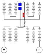
Here is a schematic of the battery without ICL:
VectrixBatteryandMotorController-2.jpg

The blue squares are the two parts of a 125A Andersons connector; it breaks the battery pack into three parts and makes it safe to disconnect the 125V pack from the MC.

The ICL needs to be connected BEFORE the parts of the blue Andersons connector are plugged together again (after a battery, MC or main fuse repair).

.


The next schematic shows the battery plus the ICL which I am prototyping at the moment:
InrushCurrentLimiterDesign4switc-5.jpg


These next picture show the half-finished prototype:


I hope this makes some sense so far...

.


Using this prototype ICL, the battery reconnection procedure would then be as follows:

Start by connecting the ICL (with the switches set as shown in the diagram and the pot turned to 5Ω).

Then connect the Ammeter to close the circuit, wait until the current has dropped and stabilized, then switch one switch at a time to reduce the resistance by a factor of about 10 each time, wait for the current to drop and stabilize each time, and last turn the potentiometer down to zero Ω.

Then the last switch could be flicked to allow higher current flow for testing etc without closing the main Andersons connector (but only if higher than 0.1A rated fuses were used).
Or (the more likely scenario), the Andersons connector can be closed with zero inrush current; after that, the ICL and ammeter get removed.
 
Here is one of my questions regarding this topic:

How much current is a resistor likely going to endure without blowing (if the current only lasts a few seconds)?

The problem at hand is that:

150V / 1800 Ω = 0.08333A

0.08333A x 150V = 12.5W

So a 10W resistor would definitely do, because it will only be used for a few seconds at 12.5W, dropping down to nearly zero watts fairly soon.

But these 10W resistors are kind of big and chunky, and I have some problems fitting them into the box I bought!

A bigger box would fix the problem by allowing space for 10W resistors, but I believe that these resistors can take a MUCH higher wattage for short periods.

That still would not really answer my question, though.

I hope that much lower (wattage) rated resistors (1W?, 3W,?) would be able to survive these conditions for a few seconds (and repeatedly, for say at least 100 times).

How does a resistors peak wattage compare to the continuous wattage rating???

What resistors and fuses should I use to build an ICL that last at least the life of the scooter AND a few dozen repairs for friends???
 
How fast do the caps discharge? Couldn't you use a resistive jumper to make one of the connections, then eliminate the jumper and connect directly after the caps are charged?

I'm not understanding why the variable control.
 
Thanks, Tyler!

The capacitors on the MC seem to discharge quite fast, I don't know why.

So far I have been using a cable with 2460Ω resistor to bridge the Andersons connector, then I remove the cables and connect the Andersons connector as fast as I can.
"Resistive jumper" is probably a much better term for it than "bridging cable"...

The problem with this approach is that the connector is difficult to grab due to it's location. It slides away underneath a foam seal.

The inrush current increases again immediately when the circuit is opened, I measured this with a DMM in series bridging the Andersons connector.

Like this:
VectrixBatteryandICLVectux-1.jpg


Initially there are about 60mA flowing with the 2460Ω resistor in line, this drops and stabilizes at around 7mA after 20-30 seconds or so.

The 125A fuse is a fast acting semiconductor fuse, capable of suffering incremental damage from brief transient pulses. It then suddenly fails some time later under normal load. This seems to be the reason for the relatively common main fuse failures of the Vectrix.

Disconnecting the resistive jumper and reconnecting the Andersons connector takes a few seconds, too long for the semiconductor fuse.

The ICL should be connected so that the Andersons connector can be pushed together at leisure whilst the circuit is already closed.

I believe the variable control (stepwise reduction of the resistance) will allow to avoid any current spikes.

I'm not sure how to calculate the inrush current caused by connecting the capacitors with near zero Ω when a 2460Ω resistive jumper is already in place. I know I can hear a small spark when I connect the Andersons connector about 2 seconds after removing the 2460Ω jumper cable.

Maybe it can be calculated like this:
XV / 0.007A = 2460Ω --> 2460Ω x 0.007A = 17V drop across the resistor???

17V / 0.1Ω (IR of the battery) = 170A inrush current ??


The potentiometer in the last step is probably just overkill! I had the 5Ω pot lying around from my fruitless attempts to quieten the cooling impellers and thought I might as well use it. The idea is to reduce the resistance by about a factor of 10 with each switch being flicked. The 2.2Ω resistor in parallel with the 5Ω pot equals 1.52Ω; that's 1/10 of the 15Ω present in the circuit before flicking the third switch. Once the current has again dropped to a stable trough value, I can then turn the resistance down to zero by turning the pot.

I'm just trying to approach this with a large safety margin. Once it works and I can measure what happens, I can throw out any unnecessary steps.
 
This doesn't directly address your questions, but...

My first inclination would be to hack a precharge circuit in parallel. If the 2.5k resistor works, put that in the precharge path (or two in series for more limiting). You could put the gizmo in there, but it seems more work than needed.

Connect the precharge connectors, then the biggies when the caps are full. No real need to open the precharge circuit until the biggies are opened.
 

Attachments

  • MMprecharge1.jpg
    MMprecharge1.jpg
    21.6 KB · Views: 7,544
Mr. Mik said:
How does a resistors peak wattage compare to the continuous wattage rating???

Most resistors can take way over their continuous rating for a short time. As long as it doesn't overheat it should be fine. You can calculate the peak current when you first connect and try to keep it down to a few amps, but don't worry about the dissipation rating.

If you have a short or battery malfunction, then the resistor could run into trouble.

You might consider using a resistor and PTC in series. The PTC will change resistance depending on current and act like a current limiter. Something like this: http://search.digikey.com/scripts/DkSearch/dksus.dll?Detail&name=LVR100S-ND
A lower amp version of this might be adequate.
 
Thanks, Tyler and Fechter!

I found 5W rated resistors, they fit into the box and will most likely be sufficient.

The 2.2Ω resistor was of course totally useless and got thrown out. The 5Ω pot alone will have the same effect.

Another lesson learned is that 100mA fuses have a resistance of about 6Ω, so they were replaced with 500mA fuses.


InrushCurrentLimiterDesign4switc-8.jpg


I can now switch these resistances (measured):
1665Ω
170Ω
20Ω
5.8Ω --> 0.3Ω
0.3Ω

The other side of the connection (with the ammeter in series) also has 0.3Ω resistance, so the lowest value is really 0.6Ω in total.

Now I just need to attach suitable clips to the cable ends: Small, well isolated clips to stick through the holes in the battery cover and attach to the correct tab without much risk of it shorting between cell body and cell terminal (green arrows in thumbnail link below); and for the other side sharpened, insulation piercing clips to attach to the main cables (blue arrows). I hope alligator clips with two of the three teeth removed and the remaining one sharpened will suffice.


The actual testing on the battery will have to wait until I need to take the battery cover off for some reason, or until I get bored enough to do it anyway. It will take a couple of hours to do.

I think I might test the ICL by connecting it to the still fully connected battery, switch the ICL to 0 Ω, and then unplug the Andersons main connector. I'll record the current flow through the ammeter, and then increase the resistance stepwise (in reverse direction to the intended current limiting procedure). That will show me the residual current values to be expected when the MC capacitors are as full as they can get at each "stage" of the current limiting / resistance switching procedure.
Then I'll record currents during the actual ICL procedure.
The results can then be compared and should allow to reduce the design down to what is really needed.

I like Tylers suggestion to permanently install an ICL and leave it connected, but this requires removal of the battery to allow secure connections to be made. That's lots of extra work. I need this experimental setup first to be sure what will work and what will not work. A proven effective design could then be installed permanently into Vectrix scooters whenever the battery is removed for some reason - like to replace a blown main fuse!

The test results will also allow to make more informed choices about which Positive Temperature Coefficient (PTC) device could be used, as Fechter suggested.

And the test results might also help to decide if a very simple solution, like a 240V / 40W light bulb, could be used safely as ICL. I tried to discuss this on V at http://visforvoltage.org/book/ev-collaborative-hand-books/6155 , but no replies so far!

This is much better, thanks again!
 
Do you want something permanent in the circuit, or do you want something you can take out once you make the connection?
 
Dave-s said:
Do you want something permanent in the circuit, or do you want something you can take out once you make the connection?
There is not much space left, particularly because I installed a lot of extra parts and cables into the battery already. The impeller forced air flow through the battery needs to be maintained or parts of it will overheat.

I would also prefer to develop a device that can be removed without leaving a trace, for the benefit of those owners who still have a warranty.
 
My idea? Spice a second connector in parallel with the first, and add a resistor in series with that. Plug in the small one, wait a few seconds, then the big one.
 
Link said:
My idea? Spice a second connector in parallel with the first, and add a resistor in series with that. Plug in the small one, wait a few seconds, then the big one.
Drat. He stole his idea back, after I stole it from him.

The goal is apparently a service appliance, that can be temporarily clipped onto any vectrix (without modding the harness).
 
TylerDurden said:
Link said:
My idea? Spice a second connector in parallel with the first, and add a resistor in series with that. Plug in the small one, wait a few seconds, then the big one.
Drat. He stole his idea back, after I stole it from him.

The goal is apparently a service appliance, that can be temporarily clipped onto any vectrix (without modding the harness).

Shows how much attention I was paying.

facepalm.jpg
 
Couldn't you do this with a really big inductor? It would have to be a huge lump of copper with an iron core, but it might help reduce inrush current.
 
Mr. Mik said:


InrushCurrentLimiterDesign4switc-8.jpg


I can now switch these resistances (measured):
1665Ω
170Ω
20Ω
5.8Ω --> 0.3Ω
0.3Ω

The other side of the connection (with the ammeter in series) also has 0.3Ω resistance, so the lowest value is really 0.6Ω in total.

..........

The actual testing on the battery will have to wait until I need to take the battery cover off for some reason, or until I get bored enough to do it anyway. It will take a couple of hours to do.
.......

A really lousy weather forecast convinced me that it was time to take the Vectux apart and test the above ICL.
Whilst much of the surrounding areas got flooded, I fiddled around with it for two days on and off.

I blew one of the 0.5A fuses in the ICL and the 0.8A fuse in my DMM in the process, somehow. I think it might have happened when I unplugged the DMM cables and plugged them back in immediately after switching polarities. The ICL might have been switched to "short" at that time and this caused enough inrush current to blow those fuses.
How much damage the 125A semiconductor fuse on the Vectux motor controller board has suffered is unclear, but hopefully none.

Unfortunately it seems that my DMM is not up to the task of measuring the short current spikes which are caused by connecting big capacitors to low resistance 130V DC.

I have to take multiple measurements and each time the peak current is different. The difference can be more than an order of magnitude, depending on ??chance??.

I believe the sampling rate of the DMM is too slow, so that the measurements taken happen either during the steep rise of the current spike, or at the top (rarely), or during the (probably less steep) fall of the current spike; sometimes it seems to miss it altogether.

The problem with this is that I need to run multiple test and hope that the highest peak current I get in the test series is close to the actual peak current.

But the semiconductor fuse on the MC gets the full analog spike each time I test and might get damaged in the process.

Here is a link to the DMM I am using: http://www.jaycar.com.au/productView.as ... rm=KEYWORD

How can I measure the peak current of each inrush current spike more reliably?

Would a better DMM be up to it? Would an oscilloscope do the job?
 
TylerDurden said:
PC-Logging scope should work.

Somebody here posted a pic of a scope that connects to USB. I can't recall exactly.

Thanks, Tyler!

I have some doubts about the use of an oscilloscope for this purpose, but they might well be unfounded.

Scopes measure voltage, not current, but that could probably be calculated via Ohms law.

More importantly, scopes measure repeating waveforms. I don't know if this single current spike (or voltage drop) can be measured by a scope. It only happens once when the switches are flicked, not dozens, hundreds of millions of times per seconds like the other stuff commonly measured with scopes.

How would a scope be connected to this circuit to measure a voltage which is proportional to the current peak?
 
I found a commercial page explaining the ins and outs of DC Inrush current measurement, trying to sell a complex instrument to do it with:
http://www2.electronicproducts.com/Characterizing_dc_inrush_currents-article-surcagilent-aug2007-html.aspx
But it gives a very good overview of the problems!
R&D engineers have traditionally found it a challenge to measure dc inrush current and current during dc voltage transients because these measurements require complex setups with multiple pieces of equipment at minimum, and may even demand writing a program to control the setup, make the measurement, and capture the data. Furthermore, determining measurement accuracy usually means performing complex calculations to characterize a multiple-instrument system’s accuracy, and the transducers used for the test can interfere with the device under test’s (DUT’s) operation. What’s a designer to do?

.........

There are also Clamp-DMM's which have an in-built "Inrush current function", like this one: http://www.hmcelectronics.com/cgi-bin/scripts/product/3410-0139/fluke-337/

But they are way to expensive for my purposes.
 
I found a way to measure the inrush current with the DMM and other equipment I already have!

When I was looking at slow motion video footage I realized that my DMM actually measures and displays the current peak quite fast, but the numerical display lags behind for a fraction of a second, missing the peak.

The DMM has a 60 point scale underneath the "6000 Count" numerical display.
Each point represents 1/60th of the maximum that can be displayed with the presently chosen display setting. When it is set to 000.0mA, then each of the 60 points underneath represent 10mA.

This 60-point scale reacts much faster than the number display, and much more consistently!


Here are some close-up pictures to show how it works. I used an 8s NiMH battery for voltage measurement to show how the 60point scale works:

DSC07285-1.jpg
DSC07284-1.jpg
DSC07283-1.jpg
DSC07288-1.jpg


This allows me to much more reliably assess if I am staying within current limits which are safe (for the 125A semiconductor fuse and the components on the motor controller board)!
 
Here is a video showing the events when the ICL Prototype is being connected to the battery in series with a 40W/240V incandescent light bulb.

[youtube]ILkzSK3ZJqY[/youtube]

The light bulb has a cold resistance of 102 Ohm and the ICL is set to 170 Ohm, making a total of 272 Ohm at the start. As soon as the globe starts to heat up it's resistance rises.

One can see the sharp rise and drop of the 60-point scale concurrent with the lighting up of the globe, before the DMM shows any rise in current!

The DMM at the rear is connected to the positive and the negative terminal of the battery (through the M-BMS => 15kOhm resistors). When the battery series is being closed (by closing the ICL switch), the voltage rises whilst current flows into the capacitors on the motor controller board. Once the capacitors are pretty much charged, the voltage is almost the same as the battery voltage (minus small measurement error due to the 15kOhm resistors and the voltage drop due to the remaining 272 Ohm), and the current becomes steady at about 7.4mA. This seems to be the current leakage through the "always on" motor controller and the voltage divider of the stock-BMS.

Below are screen shots taken during slow replay of this video. They show key frames during the short lived inrush current event:


The bar-graph reaches 220mA, the numerical display only 136mA.

The theoretical maximum would be 135V / 272 Ohm = 496mA. But the capacitors were most likely not completely discharged, and the resistance of the bulbs filament rises as soon as current begins to flow.

I believe the 220mA result is certainly in the right order of magnitude, and it is fairly repeatable!

The numerical peak results are more random, depending on when exactly the ICL was triggered in relation to the "refresh frequency" of the display.

More screen shots will be in the next post.
 
Here are the remaining screen shots from the slow motion video:


After many more tests (both before and after the ones shown above) I decided to settle with a 15W@240V incandescent globe as the easiest solution for the ICL.

(The ICL prototype with variable resistance works very well, and I will use it, if, despite using the 15W globe, I ever run into problems with blowing main fuses on a Vectrix again.)

The 15W@240V globe has a cold resistance of 320 Ohm, and in full swing this should be about 3840 Ohm. It will of course not reach this at the 140V DC, but probably over 2kOhm. I cannot measure the hot resistance and do not need to know it, anyway.

At 320 Ohm the inrush current during connection of the globe seems to be similar to the inrush current during switching from 320 Ohm to near zero Ohm.
[youtube]8s4ezOese9g[/youtube]

First the video shows connection of the 320 Ohm globe, followed by shorting of the connection with a "momentary ON" switch - the same effect as if the main connector was actually closed.
Then it shows re-connection of the globe and again switching to near-zero resistance, this time with the DMM still in series, to show the remaining inrush current caused by this.
It seems to be no more than 100mA.
 
The first commute (after several dozen tests with the ICL prototype and various light globes) went well. The fuse did not blow, yet!

I tested reconnecting the battery through these resistances:
170 Ohm, 272 Ohm, 320 Ohm, and 1670 Ohm.

I tested for remaining inrush current when switching to near-zero Ohm from these resistances:
1670 Ohm, 320 Ohm, 272 Ohm, 170 Ohm, 102 Ohm, 20 Ohm and 5 Ohm.

With all of these settings the inrush current appeared relatively safe, but initial connection with 170 Ohm and switching to near-zero from 1670 Ohm might be getting close to potentially damaging inrush currents.

The 320 Ohm light bulb (cold resistance) seems to be the best choice to me.

It's rated at 15W (@ 240V).

I guess in 110V grid countries you would need to think about which type of globe to use, and do some cold filament resistance measurements before connection to be sure.

The most important part is that the globe or ICL needs to be connected to the battery, at the right tabs, for about half a minute, and then remain connected until the blue main connector has been closed.

Connecting an ICL or globe to the terminals in the blue Andersons connector will cause short, but intense inrush currents because it takes several seconds to disconnect the ICL and to connect the Andersons connector.

Here is a video to illustrate this:
[youtube]UY-DPBFhzXs[/youtube]
 
Here is the finished product:

I installed permanent connectors to plug in the 320Ohm globe (or another ICL). An ICL could be left permanently installed, but it would need to be unplugged each time the batteries are taken out of the scooter so that they can be separated. I prefer to use a globe (over a simple resistor) because it shows clearly that the ICL is working; and I prefer to remove it after use, so that it is not exposed to the vibrations of on-road use.

The globe has a cover of hot-melt-glue to protect it from life in the toolbox and for electrical insulation. The other cable is integrated into a heat-shrink sleeve together with the cables to and from the globe.


This is a video of the actual battery reconnection process:
[youtube]9KI980QmFIg[/youtube]
 
Back
Top