
You are using an out of date browser. It may not display this or other websites correctly.
You should upgrade or use an alternative browser.
You should upgrade or use an alternative browser.
LCD screen
- Thread starter vax
- Start date

jateureka
10 kW
I think the unit uses a resistive voltage divider on the input. If you are handy with electronics you could try changing the resistor values and/or fit a 12V zener diode to drop your input down from 72V to 60V.
If someone has the higher voltage display (72V or higher) could they take a photo and post it here so we can see what the differences are on the input circuit.
If someone has the higher voltage display (72V or higher) could they take a photo and post it here so we can see what the differences are on the input circuit.
blueowl
10 µW
I have found the same LCD meter (as in the first post) even cheaper:vax said:Hi again.
I ordered combo LCD meter for my project, but I don't quite understand the speedometer part.
http://cgi.ebay.com/ws/eBayISAPI.dll?ViewItem&item=321157077858
http://r.ebay.com/v9C11M seller: exczha
It is very tempting for that price. But it would be more valuable if it can show Amps.
Yes, voltage is useful, temperature is nice to have (but I am not much interested in it). Speed/distance is more accurately displayed by my normal bike computer.

skeetab5780
1 MW
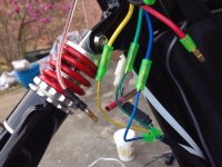
the top left white wire is the positive the bottom left wire in the picture is the negative. The top right dark blue wire will go to a phase wire on the motor/controller and the little pot adjusts the speed to your gps. Thats all you need to use if you do not want blinkers.
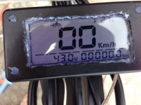
d8veh said:You must have it set to 48v, which is why it shows that you're battery is nearly empty. It doesn't know what you've actually connected. It will see a run down 48v the same as a fully charged 36v.
how to do that?
Mostly just needed confirmation on the speed wire. Am I supposed to wire this up in line? I have it going battery pos>to controller>controller negative>positive LCD>negative LCD going back to the negative of the battery. The problem is m voltage drops to 43v from 50v when the controller is added to the circuit and the throttle gives no response. I then tried using my multimeter on the negative on the controller to the positive from the battery and got 7v. So I think something is wrong here.
Stomper
1 mW
I got the same lcd and i would like to use the temp sensor to get the motor temp, does the wire lengh have an impact on the probe or i can simply cut the wire probe extend it put the probe in the motor to get motor temp on my screen?
Another thing is my screen have a clock on it but i dont know how to set it since i dont have any button on it and the seller know less about it than i do so is there a way to set the clock because now i have to power it at midnight to set the clock


Also when i ordered the lcd the first one the seller sent to me wasnt working i dont know electronic enough to find what's wrong but it must have been damaged during transport, here is a pic of what it's doing:

If one of you can salvage it from the dead i could give it for free instead of trowing it in the garbage so if you want it send me a PM. You must pay the shipping cost wich should be around 2-3$ by standard post to Canada & USA.
Another thing is my screen have a clock on it but i dont know how to set it since i dont have any button on it and the seller know less about it than i do so is there a way to set the clock because now i have to power it at midnight to set the clock
Also when i ordered the lcd the first one the seller sent to me wasnt working i dont know electronic enough to find what's wrong but it must have been damaged during transport, here is a pic of what it's doing:
If one of you can salvage it from the dead i could give it for free instead of trowing it in the garbage so if you want it send me a PM. You must pay the shipping cost wich should be around 2-3$ by standard post to Canada & USA.
mateusleo
1 kW
I have 2 questions folks:
1)The one with current sensor says to support 0-20 amps... So if i use it on a 48v-1000w motor it will probably burn out when i'm climbing a hill with a big angle, cuz the motor will slow down and the current will go over 20 amps. Am i right?
2) The headlamp and arrows wires are just to tell you if they'r actually turned on or they'r capable of turning the stuff on (Using a relay ofc)?
Stomper
1 mW
mateusleo said:I have 2 questions folks:
1)The one with current sensor says to support 0-20 amps... So if i use it on a 48v-1000w motor it will probably burn out when i'm climbing a hill with a big angle, cuz the motor will slow down and the current will go over 20 amps. Am i right?
2) The headlamp and arrows wires are just to tell you if they'r actually turned on or they'r capable of turning the stuff on (Using a relay ofc)?
1. you have to use a shunt for this and you put a 20A fuse so you wont burn it if current goes higher than 20A, the bike wont stop but the current meter will stop working until you put a new fuse.
2. it's only an indicator working at 12v maximum, so you need 12v light for this and you plug it in parallel with your headlight, dont forget to put a fuse there also, if your light is 12v 30w or less put a 3A fuse.
Dont forget tu build a fuse array for those kind of things it doesnt take much space and save everything when something fail.
mateusleo
1 kW
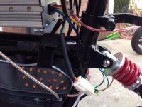
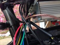
Does anyone has any idea about whats the function of this wire in the picture? Theres no picure pointing what his function

Also, if anyone knows what are the functions of the other spots that come without any wire, it would be good to know. Thanks

Also, if anyone knows what are the functions of the other spots that come without any wire, it would be good to know. Thanks
mateusleo
1 kW
More stuff, besides the unknown wire, i don't know how to make the odometer work, the ebay listing says it has single mileage and acumulated mileage, but i didn't see that...Does anyone know how to make it work?
I've got one of these LCDs and want to use it on my ver1 A2B Metro, I don't have access to the phase wires (controller is potted into the wheel) any way I can use a sensor to do the speedo? tried pulsing 5v onto the wire but only get 2k shown. Also anyone tried any of the 1,2,3,4, pins marked on the pcb? Or have a proper wiring diagram?
alsmith
100 kW
Maybe that's what the wire is for? A reset switch?mateusleo said:More stuff, besides the unknown wire, i don't know how to make the odometer work, the ebay listing says it has single mileage and acumulated mileage, but i didn't see that...Does anyone know how to make it work?
mateusleo
1 kW
I figured out the odometer, seller said that you can reset the single mileage accumulation by turning the headlight on and off 3 times, and the total mileage 5 times. He also said there's no wiring diagram. As I don't have a headlight I simply connected the headlight wire to the battery positive and its always on, so odometer works like a charm now. There are also lots of empty soldering spots on the pcb, they might have a function, will probably test it out when I get my multimeter
The 1, 2, and 3 solder pads are for assist level display, just stick 5v on them. the 4 pad didn't do anything, the RST pad does a reset when dragged to ground.
I really need to get the speedo working without phase wires, reedswitch pulsed to 36v doesn't do it, how can i simulate a motor output? Frequency to voltage converter maybe?
I really need to get the speedo working without phase wires, reedswitch pulsed to 36v doesn't do it, how can i simulate a motor output? Frequency to voltage converter maybe?
mateusleo
1 kW
O don't know if it's possible to get speed without phase. Someone asked how to adjust the clock, it's not a clock, it's a trip time counter and will reset every time you turn the lcd off
Similar threads
- Replies
- 3
- Views
- 148
- Replies
- 11
- Views
- 794
- Replies
- 3
- Views
- 806