Science, Physics, Math, & Myth

Transverse flux switched reluctance is the penultimate. Copper fills >1. No drag beyond windage and bearing friction and tire losses when unpowered.

Pretty tough to match that. And it's easy to manufacture by being wound with simple round ribbon coils.
 
John in CR said:
Your example is apples, but the other part is oranges, and the reason for that is the motors aren't compared under the same operating conditions. Assuming equal copper fill, under the same conditions they would be identical, because for one to make more torque, it makes more heat.

John,

Since these motors weigh the same, I believe that they must have exactly the same copper fill.
Still the same apples, right?

Once the chairs are moved around by tweaking voltage and motor phase amps, oranges suddenly appear.

We all see a jump in torque in Justin's Simulator (was that not the point?) - and a simple comparison of apples gets thrown away yet again?!

DENIED.
 
liveforphysics said:
Stevil_Knevil said:
Can we all agree on what 'apples' are, please?

-Battery :arrow: 66V 4.6Ah Dewalt
-Controller :arrow: 40A IRFB4110
-Wheel diameter :arrow: 23.5"

OK, good. Let's put these on our test bench.
Aside from the enable switch and throttle (100%), we will NOT touch anything except for the phase and hall connectors from the controller!!

Next, let's head over to Justin's eBike Simulator -> http://www.ebikes.ca/tools/simulator.html

..and connect our apples to a 'HS' (High Speed) motor ->
http://www.ebikes.ca/shop/ebike-parts/motors/m3548r.html

..then compare performance using the same apples with a 'HT' (High Torque) motor ->
http://www.ebikes.ca/shop/ebike-parts/motors/m3525r.html

I see a table full of apples - SIGNIFICANTLY higher torque from the HT - and no Myths!


Yep, if you go with less turns, you have need to increase phase current proportionately to get the same torque (notice this doesn't make any difference in power drawn from the battery, because it's proportionately higher phase current at proportionately decreased phase voltage ).

Hey! Fingers off the phase current dial, buddy :wink:
 
Stevil_Knevil said:
liveforphysics said:
Stevil_Knevil said:
Can we all agree on what 'apples' are, please?

-Battery :arrow: 66V 4.6Ah Dewalt
-Controller :arrow: 40A IRFB4110
-Wheel diameter :arrow: 23.5"

OK, good. Let's put these on our test bench.
Aside from the enable switch and throttle (100%), we will NOT touch anything except for the phase and hall connectors from the controller!!

Next, let's head over to Justin's eBike Simulator -> http://www.ebikes.ca/tools/simulator.html

..and connect our apples to a 'HS' (High Speed) motor ->
http://www.ebikes.ca/shop/ebike-parts/motors/m3548r.html

..then compare performance using the same apples with a 'HT' (High Torque) motor ->
http://www.ebikes.ca/shop/ebike-parts/motors/m3525r.html

I see a table full of apples - SIGNIFICANTLY higher torque from the HT - and no Myths!


Yep, if you go with less turns, you have need to increase phase current proportionately to get the same torque (notice this doesn't make any difference in power drawn from the battery, because it's proportionately higher phase current at proportionately decreased phase voltage ).

Hey! Fingers off the phase current dial, buddy :wink:


Why though? Silicon power density continues to improve greatly year after year, why are we running the same voltages.
 
liveforphysics said:
Transverse flux switched reluctance is the penultimate. Copper fills >1. No drag beyond windage and bearing friction and tire losses when unpowered.

Pretty tough to match that. And it's easy to manufacture by being wound with simple round ribbon coils.

The motor in the video I linked to is a tranverse flux switched reluctance machine but note it has single piece ring shaped permanent magnets (no futzing with gluing hundreds of magnets). This is not so it works like a standard BLDC, but to provide a linearly increasing flux linkage over the pole overlap area.

The penultimate motor is currently a tubular flux switching motor. Imagine a tubular halbach array flux switching linear motor and roll it up into a circle. Now provide a slot to allow for rotation. Maximum air gap flux area possible but requires sl-smc material for the 3d flux path.

The increased drag of an idle or unpowered motor with permanent magnets is trivial for large EVs. For a ebicycle it would feel great to pedal with an ultra low drag switched reluctance hub motor, or you could have a permanent magnet motor and just add a simulated ZERO DRAG mode to your controller to effectively elimate the losses from the magnetic field always being on, AND bearing friction AND tire losses! You will roll forever on flat ground and it will pedal like a dream with zero throttle.
 
liveforphysics said:
Transverse flux switched reluctance is the penultimate. Copper fills >1. No drag beyond windage and bearing friction and tire losses when unpowered.

Pretty tough to match that. And it's easy to manufacture by being wound with simple round ribbon coils.
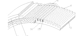
Is there any reason one could not be DIY built via crowd-sourcing? Or is the controller too hard for switched reluctance? If so, how about permanent magnet transverse flux?
 
Stevil_Knevil said:
John in CR said:
Your example is apples, but the other part is oranges, and the reason for that is the motors aren't compared under the same operating conditions. Assuming equal copper fill, under the same conditions they would be identical, because for one to make more torque, it makes more heat.

John,

Since these motors weigh the same, I believe that they must have exactly the same copper fill.
Still the same apples, right?

Once the chairs are moved around by tweaking voltage and motor phase amps, oranges suddenly appear.

We all see a jump in torque in Justin's Simulator (was that not the point?) - and a simple comparison of apples gets thrown away yet again?!

DENIED.

Yes Stevil, you're entitled to believe the earth is flat if you choose. Just don't go around preaching it to other people, because those days are over.
 
liveforphysics said:
Why though? Silicon power density continues to improve greatly year after year, why are we running the same voltages.
There is a limit to everything.

Running uber high amps is not easy as you increase the Phase amps the noise increases and your demand on other things increases.
Inductance is also another issue. As you run 2x the voltage for the same rpm you get 4x the inductance which is good for the controller but also allows better use of field weakening.

I think the goal as always is to run the most phase amps you can at the lowest voltage to achieve the goal KW you desire.
 
liveforphysics said:
johnrobholmes said:
I'm with you on single or half turn coils (wouldn't it only be a half turn if the phase starts and stops on opposite sides of stator?) being an ultimate design, although the labor saved in winding seems to be offset by the trouble to get all the coils connected in my limited experience.

Believe it or not, a winding scheme is possible that requires only 3 continuous pieces of wire taking an alternating weaving course through the teeth. If delta terminating, no connections are even needed, if wye, a single crimp joint.

Andrej Detela's new radial flux permanent magnet motors using this a new type of wave winding (wave winds and lap winds have been around a long time), but uses a double layer helical technique. Very high pole counts are possible with very high copper fill. You will also notice the length of the end windings are much shorter with this technique than the typical wave wind (you have to skip teeth). Very similar to the Remy hairpin winding but which each layer rotated 180 degrees for even shorter end turns.

wave.PNG

notice on the remy the helix alway turns in the same direction (twisting counterclockwise as you travel left in this picture)
 
Arlo1 said:
I think the goal as always is to run the most phase amps you can at the lowest voltage to achieve the goal KW you desire.


I'm with you on that my friend. As silicon dice continue to improve, the ideal voltage will continue to shift downward.

15years ago the typical voltage for a typical 500-2000W ebike was maybe 36-48v.

Now we have MOSFETs and gate drive skills to enable switching much higher currents with tiny lightweight low cost controllers, but ebikes are still 36-48v for the 500W-2000W power range.

For bikes used for practical transportation power levels, it would be quite reasonable now to use perhaps 4s or maybe 6s if you wanted a few kW. This would make pack management so dead easy, and balance charging could be dirt cheap with just 4 DC-DC converters.
 
liveforphysics said:
Arlo1 said:
I think the goal as always is to run the most phase amps you can at the lowest voltage to achieve the goal KW you desire.

I'm with you on that my friend.

True drag racers at heart. For a given motor, as long as no load current remains acceptably low (ie iron core losses lower than copper losses at typical cruising speeds on flat roads) and gearing can be lowered without noise or additional losses, then I want to run as high a voltage as possible in order to keep current as low as possible for the power I want. I simply can't ignore that copper losses increase by the square of current.

That's not to say I don't want motors with as few turns as possible with efficient durable controllers to drive them in order to lower pack voltages. With one in hand though, I'll still want to run it at as high a voltage as possible to lower current for a given power.

Heat is the enemy. I don't care if a motor can handle high temps, since copper losses can easily increase by 40-50% or more just due to increased temperature. Instead I want a motor that makes so little heat it never gets to high temperature. The easiest way to keep a motor cool is by creating as little heat as possible.
 
John in CR said:
liveforphysics said:
Arlo1 said:
I think the goal as always is to run the most phase amps you can at the lowest voltage to achieve the goal KW you desire.

I'm with you on that my friend.

True drag racers at heart. For a given motor, as long as no load current remains acceptably low (ie iron core losses lower than copper losses at typical cruising speeds on flat roads) and gearing can be lowered without noise or additional losses, then I want to run as high a voltage as possible in order to keep current as low as possible for the power I want. I simply can't ignore that copper losses increase by the square of current.

That's not to say I don't want motors with as few turns as possible with efficient durable controllers to drive them in order to lower pack voltages. With one in hand though, I'll still want to run it at as high a voltage as possible to lower current for a given power.

Heat is the enemy. I don't care if a motor can handle high temps, since copper losses can easily increase by 40-50% or more just due to increased temperature. Instead I want a motor that makes so little heat it never gets to high temperature. The easiest way to keep a motor cool is by creating as little heat as possible.


Your heating is still just going to be the inefficiency of the system. You can be lower voltage and also higher efficiency.
 
Stevil_Knevil said:
Can we all agree on what 'apples' are, please?

-Battery :arrow: 66V 4.6Ah Dewalt
-Controller :arrow: 40A IRFB4110
-Wheel diameter :arrow: 23.5"

..and connect our apples to a 'HS' (High Speed) motor ->
http://www.ebikes.ca/shop/ebike-parts/motors/m3548r.html
..then compare performance using the same apples with a 'HT' (High Torque) motor ->
http://www.ebikes.ca/shop/ebike-parts/motors/m3525r.html

I see a table full of apples - SIGNIFICANTLY higher torque from the HT - and no Myths!

John answered this pretty well but there are a few additional points I'd like to make. One is that the Crystalyte motors do NOT necessarily all have the same copper fill, and usually the very fast wind motors end up with a lower stuffing because of the physical challenge to deal with hand winding a huge parallel strand count. So I'm pretty sure that the H3548 is this way, much like how the Crysatlyte 5303 had a lower copper fill than the 5304 because they used the same stranding but just did 3 turns instead of 4 turns. This is where the "X x Y" designation, confusing as it is, at least has some benefit that you can see the actual total copper strands. So the Nine Continent 7x9 windings clearly has a bit more copper than the 10x6, (63 strands vs. 60) so you'd expect somewhat better torque all else, but the 9x7 was identical.

When you compare two motors that do have the same fill, like the slower 7x9 with the faster 9x7, you still get a difference in the torque output off the line, because the faster winding motor needs more current to produce the same torque, and outside the motor, more current means more losses in the motor controller and motor phase leads (but not the battery leads, as the battery current stays the same).

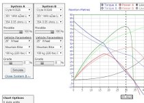
Here for instance is a comparison with the slow wind H3525 and the fast wind H3540, using a controller with 50 mOhm combined mosfet + lead resistance. Clearly the actual torque output at low speeds is about 10% higher on the slow motor:
Simulator Comparison, 50mohm.jpg

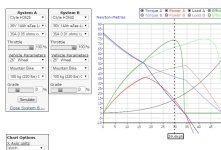
Now replace the controller on the Faster 3540 winding with one that has fatter gauge wire so that it's only 10mOhm of resistance, and you can see that the torque difference between the two systems almost completely vanishes
Simulator Comparison, 10mohm.jpg

Hopefully that gives some clarity on why you do both in practice and on the simulator see more torque with the slower motors. It's not that the fast motors produce less torque, but as a system with the same controller and phase wiring gauge then no doubt the motor that draws fewer amps will have less losses outside the motor, and that means more total power flows into the hub.

To me, an apples to apples comparison means that when you select a low turn motor, you are running at a lower voltage and higher current in general, so your phase wire gauge, controller mosfet resistance etc. should scale down accordingly so that the external losses are the same. In that apples to apples sense, motor winding really makes no difference as the graph above shows. The blame for lower torque with the fast motor does not lay in the motor, but in the controller and external wiring.
 
justin_le said:
Now replace the controller on the Faster 3540 winding with one that has fatter gauge wire so that it's only 10mOhm of resistance, and you can see that the torque difference between the two systems almost completely vanishes


Hence where next generation modules come in. This chip is <$20 in quantity, just add caps and one of the automotive shoot-through protection and de-sat protection enabled 6-pack FET driver chips for another couple bucks and you've got something ready for making high performance ~4s-6s battery ebikes.

http://ixapps.ixys.com/Viewer.aspx?p=http://ixapps.ixys.com/DataSheet/MTI200WX75GD.pdf

Maybe combine with an auto-precharging contactor module that handles "150A" or whatever (easily taking bursts of many times that amount), the contactors are available <$10-20 and DC rated. I know you don't generally run more than 3-4kW if I'm not mistaken Justin. This is comfortable territory for pioneering some kick ass high efficiency high performance lower voltage stuff just for kicks (or eventually to save money on BMS channel and management cost and ideally make inherently more reliable systems).
 
flathill said:
Very similar to the Remy hairpin winding but which each layer rotated 180 degrees for even shorter end turns.

View attachment 1

Hi flathill,

I don't follow your logic about endturn length, but that seems to be construction detail and a bit off-topic. But I did want to explore further the wavePNG diagram. Do you have a source for it? I searched and did not see any such work by Mr. Detela although there is quite a bit about his other designs using concentric winding. Those remind me of the alternator fields :wink:

Thanks,

major
 
justin_le said:
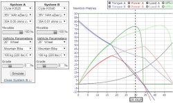
Now replace the controller on the Faster 3540 winding with one that has fatter gauge wire so that it's only 10mOhm of resistance, and you can see that the torque difference between the two systems almost completely vanishes
Justins simulation.JPG
Virtually identical performance, efficiency, torque, acceleration, etc. up to 17kph. Before the slow wind guys cry foul and say, "wait that's not fair, the fast motor gets more current.", it actually draws the same current from the battery up to 17kph as demonstrated by the matching efficiency curves. The controller just sends a different pulsing signal to the speed motor so it sees a lower voltage with higher phase current. Above 17kph is where it's interesting, because the greater torque of the speed motor the slow wind motor is rapidly behind never to catch up. Power with the speed wind continues to climb while the power from the slow wind motor falls off rapidly. While it makes more heat in the process of making more torque just as the slow wind motor does in any condition where it has greater torque, you can still make the speed wind perform identically (same efficiency, etc) at any cruising speed for which the slow motor is capable. Simply back off the throttle, use a CA to limit max speed, etc.

The price of thicker wiring and a larger controller is a small price to pay for the far greater mid-range performance, and greater top speed, while still having identical performance at lower speeds on the hills. Why stop there? Use a smaller wheel, that the higher rpm range permits without giving up top speed compared to the slower motor, and then you get better hill climbing, better acceleration at any speed, better efficiency at any cruising speed, and better efficiency during acceleration from 0 up to a point somewhat higher than the 17kph point of divergence in Justin's graph.

For the guys chasing higher power, you can improve even further. Why set the current so high, since you already had too much torque at 0 rpm with the short wheelbase, high CG bikes typically used? I understand that it's really the mid-range torque you're after, and to get it you have to use artificial means to make the bike controllable on the launch, which is often more pronounced with slow winds. This is due common tendency to lean on them harder due to people not considering phase resistance or winding when setting current limits. If you use the speed wind motor and don't turn the current up high enough to make so much wasted launch torque, the result is greater efficiency during the first part of acceleration, but you still end up with greater torque through the mid-range for a cooler motor and better performance. If you feel that you'll get carried away by having too much top end speed, simply limit the top speed. Limiting top speed doesn't mean you have to give up any of the increased acceleration that the faster wind motor offers, and acceleration is the beautiful thing about our ebikes.
 
Great work on this miles. Super thread. Nice to see all of the motors compared this way. Is the joby really that good? :mrgreen: Wish it had a option for a short drive shaft exiting the mount side. May not matter on a sturdy bike mount. Would love to see charts on how the foc type controllers would work with it and the other RC and small mid drive suitable motors.
 
If air gap diameter is now the standard since stator diameter is gone, please just add 1mm to the 2 mine. It may not be exact, but close enough. I'll measure next time I open a motor, something I try to minimize because the magnet stator coatings get scraped.
 
John in CR said:
If air gap diameter is now the standard since stator diameter is gone, please just add 1mm to the 2 mine. It may not be exact, but close enough. I'll measure next time I open a motor, something I try to minimize because the magnet stator coatings get scraped.

It's the same measurement for inrunners and outrunners and can be multiplied directly by the stack height to get the airgap area. For most cases, adding 1mm to the stator OD (outrunners) or subtracting 1mm from the stator ID (inrunners) is accurate enough. For axial flux, I guess we need inner and outer stator diameters...
 
Here's the latest version.

I'll launch this one in a new thread, after the holiday, unless anyone suggests further changes..
 

Attachments

  • Motor Data 0.64.ods
    35.4 KB · Views: 57
  • Motor Data 0.64.xls
    137.5 KB · Views: 59
Good thread!

It has been pointed out several times, and rightly so, that the slot fill would not intentionally be compromised significantly by a motor builder when changing the number of turns in the stator winding. This makes the comparison between lower and higher turn count motors realistic.

But also in the real world aren't most garden variety ebike speed controls current-limited? Wouldn't this give higher turn count motors more low speed torque when the current limit is reached accelerating or climbing a hill?
 
Take a look at Justin_le's post above on Dec 19th. The first chart shows a fast and slow wind motor on the same controller and current limit, with the slow wind having about a 10% torque advantage upto ~18kph, then a serious disadvantage after that.

The second chart shows the effect of reducing the controller and wiring resistance on the controller for the fast wind (but keeping the same current limit), which removes this low-speed torque advantage, leaving both motors equal upto @18kph and the fast wind having the advantage after that.
 
I have some motors with series/parallel switching of the windings, and the Kv difference in high vs low is essentially 2x1. The comparison of the 2 motors in Justin's simulation matches real world results with my 2 speed motors in that the torque increase in low is barely noticeable, and that's with the same controller and settings. With common controllers when we talk about current limits that's the current from the battery, but for the motors and torque phase current is the determining factor.

With the lower speed motor, or low speed switch of the windings on my motors, I believe the reason we don't see the high torque we would expect using the same controller is because the PWM causes a higher apparent voltage to be sent to the motor and that results in lower phase current. Then the high speed motor sees a higher phase current than the low speed motor, so torque is closer to equal. Hopefully one of those who really understands controllers will step in and explain it better, and/or correct where I'm wrong. Another question for that topic is "Why isn't the difference in the same relationship as the difference in winding? Is it the difference in phase resistance and inductance?".
 
Back
Top