GM "Magic" controllers

oldhaq

100 W
Joined
Oct 25, 2008
Messages
264
Location
Redcliffe, Queensland, Australia
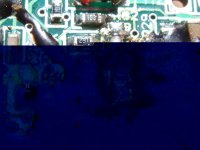
I took apart my magic controllers and took some pics.


the 36v;
magic36v1.JPG
file.php

magic36v2.JPG
file.php

magic36v3.JPG
file.php

magic36v4.JPG
file.php


the 48v;
magic48v1.JPG
file.php

magic48v2.JPG
file.php


Notice a big difference between both boards is that most of the components are mounted on opposite sides,
and no shunt bar on the 48v. I added some wires from the negative connector to the fets on the 48v as there was only (wideish) foil trace before,
it had very poor acceleration and top speed but it now goes like the clappers! Harder than the GM 48v standard controller on my usual ride.
With a shunt mod these controllers do seem like "magic". Before the mod, the wattsup measured 22a max draw, haven't measured it since tho, feels like over 40a.

75v120a mosfet datasheet ... http://www.datasheetcatalog.org/datasheet/stmicroelectronics/9231.pdf
The 3 largest caps are 63v470uf.
 
Hi,

I also run a golden motor front wheel that I purchased two years ago. Last winter, I tried to modify the controller from 36V to 48V and it worked a little but my Lifepo4 batteries were always a little too powerful for the resistance I'd put on the board (this in on a thread somewhere) . After a few trips to the electronic store, I gave up and bought a new 48V controller from GM.

I'm interested in what you did to it so that it delivers more amps to the wheel. My top speed right now is 42 km/h and I find the pull to be acceptable but there is always room for improvements which you seem to have found a 'magic' way to do.

Can you show us pictures of what you did or somewhat of a step by step description. You mention wires going from the (-) to the frets. How do I go about doing this ? what gauge of wire have you used ?

I do think that my e-bike goes very fast right now. This morning, I avoided a front-end collision with another cyclist by doing what I can only describe as a 'mission impossible' stunt. Turning a corner at high speed, this cyclist appears right in front of me. I slammed on the brakes and rode the front wheel for at least 10 feet. I was convinced the back wheel would slam the guy's cheek. I could feel my front tire absorbing the decellaration as if it was a rubber band collapsing on itself. I avoided the guy whose eyes were very scared, dropped the rear wheel on the ground, excused myself and zoomed out of there real quick.

Anyway, just have to careful on corners. I usually ride late at night when it's safest.

Well, let us know how to go faster.
 
I couldn 't figure out how to place all the pics inline on the first post, kept trying but only the 2 pics would show up, at least they're the 2 that show the full board for each controller. (edit: managed to get them all to display, sort of)
I've run the wattsup again and it showed momentary peak draws of up to 92A from low rpm :shock: tho was usually between 40-60A under hard acceleration.
I think I had better take it a bit easier or somethings gotta give at that rate.
Got my first good whiff of hot motor windings now too.
I forgot to mention before that the 36v controller blew a week ago while sitting in my driveway, I rolled back a few inches and applied a little throttle and that was it. A blue side fet went. I suspect the motors' delta wiring may be the cause of that (edit: most likely just from rolling back with throttle).
tapholov said:
Can you show us pictures of what you did or somewhat of a step by step description. You mention wires going from the (-) to the frets. How do I go about doing this ? what gauge of wire have you used ?
I used 250v10a house mains wire, connected as in this pic...
magic48shunt_mod.JPG
I'm going to change the wire gauge to reduce the amp draw, it can't last like that, can it?
 
Hi.
Sounds good that mod.
Could you please just confirm how to do it,
EG:
Like in your picture, I am assuming where the red lines go you put wire?
And on the dots it makes contact? Looks like there a 3 lengths of wire you would use?
Is it insulated wire? Did you strip it back for where the dots are? Or use heaps of little lengths to joing between the dots?


Would be great to see a picture of it with it actually done. It might make it easier than explaining lol.

Thanks heaps.
 
Well something did give, the controller, but the little soldier managed a peak output of 4.8kw/114a at that point. :shock: :shock:
When running well, 90A draw:
magic48vLIMITw.jpeg

Didn't run after this:
magic48vLIMIT.jpeg
It was no great loss, as GM sent them to me by mistake anyway, and I have some exact replacement fets already on order.
It was certainly a new and exciting experience having the front wheel lift on an e-bike. A must-have now for me on one of my bikes.
SkyCaptain said:
Hi.
Sounds good that mod.
Could you please just confirm how to do it,
EG:Like in your picture, I am assuming where the red lines go you put wire?
And on the dots it makes contact? Looks like there a 3 lengths of wire you would use?
Is it insulated wire? Did you strip it back for where the dots are? Or use heaps of little lengths to joing between the dots?
Would be great to see a picture of it with it actually done. It might make it easier than explaining lol.
Thanks heaps.
that's all, just 3 pieces of insulated wire between each point/dot. It's not adding any connections, only beefing-up the copper to the transistors.
 
When I replace the fets I'll take a picture, but I will leave only 1 wire connected to the left side of the board and see how it goes.
 
While you are in there can you get a part number off the controller.

It would be interesting to know the manufacturer and if the programming could be changed.
 
It looks like a version of the 36v magic controller is in Hyena's review sample of the Magpie, so thought I'd post an update.
The PCB in my controller (RIP, has since been used for parts) is MX307, the Magpie is MX312. There appears only a few minor differences in small circuit traces, and the main caps mounted reverse side. It'll be interesting to see the shunts and what the built-in controller can achieve without airflow, as they got only very slightly warm stock standard (22A max), and the hottest I recall when stress testing (usually only 10min runs @ 40A to 90A peaks) would've been about 60-70 C.
The part number of main DIP was scratched off.
I did fit some new fets to the 48v, but it was no-go so it's RIP now too, don't have time to fault-find these things too much.
 
In the 5th pic (48v) there's an area in the black resin sealer which had been dug out and a component removed. It might be hard to know why though unless GM can tell, and whether there is a corresponding part on the 36v or Magpie (being (very) hopeful here).

file.php


PCB number on the 48v is MX203.

Fyi, I just viewed this page in IE and saw that most of the images don't appear, I use Firefox which does show them, not sure what's going on there. If you use Firefox try the add-on "Image Zoom", just right-click an image and scroll.
 

Attachments

  • magic48vresin.JPEG
    magic48vresin.JPEG
    71.7 KB · Views: 4,580
oldhaq said:
It looks like a version of the 36v magic controller is in Hyena's review sample of the Magpie, so thought I'd post an update.
The PCB in my controller (RIP, has since been used for parts) is MX307, the Magpie is MX312. There appears only a few minor differences in small circuit traces, and the main caps mounted reverse side. It'll be interesting to see the shunts and what the built-in controller can achieve without airflow, as they got only very slightly warm stock standard (22A max), and the hottest I recall when stress testing (usually only 10min runs @ 40A to 90A peaks) would've been about 60-70 C.
The part number of main DIP was scratched off.
hi oldhaq, I tried to figure out some of the circuitry in the BAC281 (http://goldenmotor.com/SMF/index.php?topic=1151.msg6451#msg6451) in order to find internal connectors/pads for the cycle analyst. Most eagerly I was looking for a shunt as I want to measure the current without installing an external resistor. What do you mean with 'shunt bars' - that the copper bars on the pcb are used to measure the motor current?
We have a number of e-velos running with GM equipment (and experienced some damages too http://goldenmotor.com/SMF/index.php?topic=987.msg5853#msg5853 and http://goldenmotor.com/SMF/index.php?topic=1324.0). We measured the current delivered by the controller and it is ca. 20A. Up to no we thought it is limited by the controller software (assuming there is a current measurement somewhere). Reading your post it now seems to be the internal resistance which keeps the current limited. I would love to increase the torque (=current) so I might try to test your suggestion.
I would be interested to know if somebody figured out what the brand/type the controller chip is...
The different pcb versions (same voltage but purchased 2008 and now) are quite differently built - I dont know if they also changed the circuit besides the layout...
r
 
Is it same layout as one of the above, or can you post a picture of each side of the PCB?
If it is the same as the 48v above, I suppose you could cut the copper trace that feeds the fets then put a shunt across the cut for your CA.
Shunt bars on the 36v are bottom right corner of this picture;
 
It's not really clear from your pictures, but how are those FETs attached to the case for heatsinking? It seems like the only mounting method that board configuration would allow is a compression fit (is that hotglue or silicone underneath the FETs?). That's really shaky from a thermal perspective. The biggest problem would be consistency - you might have 5 FETs making decent contact but one that's only kinda touching, and even a tiny airgap will make a HUGE increase in the thermal resistance. As soon as it starts to draw significant power, that one FET is in serious jeopardy. Please tell me there's something I'm not seeing that allows the FETs to be screwed into a heat-sinking surface. I'm also not seeing any thermal grease, so hopefully you cleaned that off.
 
oldhaq said:
Is it same layout as one of the above, or can you post a picture of each side of the PCB?
If it is the same as the 48v above, I suppose you could cut the copper trace that feeds the fets then put a shunt across the cut for your CA.
Shunt bars on the 36v are bottom right corner of this picture;
The older BAC's use the layout of the 48V version in your photos - the newer ones your 36V version, regardless of the voltage. I still do not understand why you call the copper bars and the thick wire bridge a 'shunt bar' - are they used to measure the current (in this case the battery current)? checking the circuit I couldn't detect components on either side of the shunt bars which could serve as voltage pick ups. And the bar material, Cu, is not well suited for a shunt resistor.
I also do not understand why your increasing of the conductor cross section in the supply lines would increase the max current so dramatically. I did ask GM about the current limitation and I was told, that the controller limits the current to ca. 30A. They didn't explain how this is done but I think it is a crude measurement of a voltage drop over some built-in resistance (possibly the FETs or some connector such as the 'shunt bars') which is used to limit the average current via the PWM. I would then guess that your added wires decrease these measuring resistors and thus make the controller 'think' it runs on lower current.
Have you experimented with different connections to find the ones which work? have you started to play with decreasing the additional Cu cross section?
r
 
rhitee05 said:
It's not really clear from your pictures, but how are those FETs attached to the case for heatsinking? It seems like the only mounting method that board configuration would allow is a compression fit (is that hotglue or silicone underneath the FETs?). That's really shaky from a thermal perspective. The biggest problem would be consistency - you might have 5 FETs making decent contact but one that's only kinda touching, and even a tiny airgap will make a HUGE increase in the thermal resistance. As soon as it starts to draw significant power, that one FET is in serious jeopardy. Please tell me there's something I'm not seeing that allows the FETs to be screwed into a heat-sinking surface. I'm also not seeing any thermal grease, so hopefully you cleaned that off.
The board is mounted to the case using the 3 screws through the other side, which in turn holds the back of the fets against the case, between which there is a strip of silicone with clear heat compound, indeed a crude method to transfer the heat.
rolf_w said:
The older BAC's use the layout of the 48V version in your photos - the newer ones your 36V version, regardless of the voltage. I still do not understand why you call the copper bars and the thick wire bridge a 'shunt bar' - are they used to measure the current (in this case the battery current)? checking the circuit I couldn't detect components on either side of the shunt bars which could serve as voltage pick ups. And the bar material, Cu, is not well suited for a shunt resistor.
I also do not understand why your increasing of the conductor cross section in the supply lines would increase the max current so dramatically. I did ask GM about the current limitation and I was told, that the controller limits the current to ca. 30A. They didn't explain how this is done but I think it is a crude measurement of a voltage drop over some built-in resistance (possibly the FETs or some connector such as the 'shunt bars') which is used to limit the average current via the PWM. I would then guess that your added wires decrease these measuring resistors and thus make the controller 'think' it runs on lower current.
Have you experimented with different connections to find the ones which work? have you started to play with decreasing the additional Cu cross section?
r
I thought most people call them shunts or shunt bars, buss bars sometimes, and copper bars or thick wire bridge less so, sorry if my terminology confuses you but I'm sticking with it. My understanding is they limit the supply current DIRECTLY, and in turn set the max power output. There's many instances in these forums where someone has modified or "soldered the shunt" to adjust the power output of their controller.
What's wrong with copper? Seems to be widely used with different gauges and number in most controllers I've seen.
As I mentioned before, these are no longer in action so no more testing on my part. I have though adjusted the shunt in other type controllers to change power output up or down.
 
oldhaq said:
75v120a mosfet datasheet ... http://www.datasheetcatalog.org/datasheet/stmicroelectronics/9231.pdf

I appreciate this is an old thread, but with winter approaching I soon won't be using my bike much so I'd like to have a go at this mod. I'd like to run about 50A if possible (still at ~48V).

Would it be a wise precaution to replace these FETs with some better ones I can find in the UK? I'm thinking that replacement before the old ones fail could potentially save other parts of the circuit being trashed (that I wouldn't be able to fix).

I figure I can finesse the current increase using the software if I initially overshoot my target :)
 
From memory the fets were a bit of a pain to remove, the legs fit tightly in the pcb holes, I'd just try it with the stock ones, they can handle a fair bit. Work your way up from shorts bursts checking the heat.
I ran them in a 12 fet infineon at 60v ~ 70-80A for a few years and it's still going.
And if it blows just get a couple of 6 fet kits from keywin and put some fets in that, worth it for the 120% throttle setting alone I reckon.
 
Ok, I'll check the FETs when I crack the case open to see if they're still using the same ones :)
 
I managed to get the silly triangular security screws out of my controller and crack it open. It's a bit different inside to either the 36 or 48V ones in the OP's post.

FET code is 140NF75 (75V 120A, apparently)

There is more solder on the traces and some copper wire added. I'm tempted to add a little more in places.

magic_controller_rear.jpg

The little link (indicated) seems to just carry power from the B+ tab to a pin on the I/O molex connector.


magic_controller_front.jpg

To my eye this looks like the current measuring shunt? It bridges B- to the source on three of the FETs.

I think I'll remove the cap next to it, beef up the thin section of trace here (there's room) and try adding some copper in parallel.

Any suggestions on roughly what sort of cross section copper I should used compared to the shunt in order to double the current? A rough percentage would make for a helpful starting point :)

Ant
 
i really wanted to upgrade the caps, but nothing over 63v would fit in the gap in the case off farnells website. If i could do the alu metal work id like to create a spacer piece but in alot of respects its just not worth the effort, these controllers are really pricey for what they are. better fets? well maybe to up the Amp rating but are the fets the only thing which is vunerable to high amps. the shunt is so close to the caps i guess if that gets super hot from high amps the cap next to it will certainly pop. I seem to remember Karma (es member) trying to mod these and oil cool them but he gave it up as a bad job.

reason i like these is much better regen than a huatong (which is probs not regen and about half a second after you want it)

Any busted gm controllers in the UK? id love to have more.
 
potential in stock UK (at farnell n channel mosfets to220(AB) type) for magic controller upgrade. Use at own risk.

PSMN3R5-80PS 80volt 120a 0.003ohm Rds On

STP210N75F6 75volt 120a 0.003ohm Rds On

IRFB3077PBF 210A 75V 0.0033ohm £3.59 each

AUIRFB3207 170A 75V 0.0036ohm £3.83 each

FDP047N08 164A 75V 0.0037ohm £2.52 each

AUIRF3808 140A 75V 0.0059ohm £2.10 each

IRF3808PBF 140A 75V 0.007ohm £1.28 each
 
lift a leg off the current shunt and twist some copper wire tightly around/along half of it and (preferably silver) solder it together, try to leave approx half the shunt untouched by copper or solder (wrap alfoil). That will halve your shunt resistance. That's assuming you don't already have another shunt to run parallel with that one.
btw, I've got a dozen or so of the same fets if anyone wants any.
 
Thanks oldhaq, that makes perfect sense.

whereswally, I'm going to have a go at modding this controller because I already have it, like its features and the wiring on the bike is already set up for it. I'm not going to push it to destruction, When I want more power I'll probably follow Jeremy's advice and buy a bare controller and fit my own fets. The motor will need wiring and temp. sensor upgrade before that.
 
Punxor, I'm with you on the gm controller. I have two now think I'm going to try run is on 14s lipo which is nearly its caps voltage limit. But would like to put some awesome amp in you can get irf3077 in tens from digikey in the uk. Could get 12 for about £30. If you want to go half and split the cost of a group buy on these fets? Any other takers?
 
I'm going to see how it runs on the original fets first. About the only advantage of having it mounted on the front of the seat post is I can always feel how hot it is on my legs :wink:
 
Back
Top