On the Saturation Current of Hub Motors & Simulator Accuracy

justin_le

Administrator
Staff member
Joined
May 28, 2007
Messages
2,299
Location
Vancouver
This is somewhat in response to the following threads:
http://endless-sphere.com/forums/viewtopic.php?f=3&t=13664&p=206093
http://endless-sphere.com/forums/viewtopic.php?f=2&t=13825&p=206434
etc.

Anyways, on the subject of the overall accuracy of the motor simulator, it's been fairly easy to confirm the simulation with actual test data in the mid to the upper end of the speed range. With direct drive hub motors, the results in the designed power levels are about as good as we could expect.

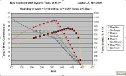
For instance, I put the 2805 winding Nine Continent motor up on the simulator database over a month ago without having actually tested it, just by extrapolating the parameters that we'd expect based on the known parameters of the 2806 hub (so 6/5 the RPM/V, (5/6)^2 the winding resistance and winding inductance, and 6/5th the no load current). Just last week I got around to doing an actual dynamo test to see how the real data stacked up against the simulator. I used a nominally 35A controller that had an actual current limit more like 38A. This is the result based on the motor parameters originally selected:
2805 Test vs Simulator.jpg

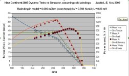
Not bad for sure, but it could certainly use a bit of tweaking. Before I began the dynamo test, I measured the actual motor phase resistance by putting exactly 10.0 amps through one of the windings and looking at the voltage drop. 0.96 volts meant just 0.096 ohms of winding resistance. Plugged that value into the simulator, adjusted the kV ever so slightly, and got this:
2805 Test vs Simulator with cold windings.jpg

Notice how at the high end of the speed range the measured data plots against the simulator results almost perfectly, you couldn't really ask for a better fit. However, as the motor gets more and more loaded, the data starts to deviate, and below about 300 rpm you can really see that the measured torque, power, and efficiency are all lower than what the simulation curves predict.

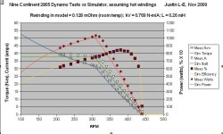
The whole process to measure the torque and current on the dynamo, slow the load motor down by 10rpm, repeat the measurements, etc. takes about 15-20 minutes. By the END of the dynamo testing (note that the data is collected right to left, I finished with the 200rpm values), the motor windings had heated up somewhat, it now measured at 0.128 ohms.

So, plug the end-of-test motor winding resistance into the simulator parameters, and now the graphs look like so:
2805 Test vs Simulator with warm windings.jpg

ie. now the data matches perfectly at the loaded end where the windings had heated up, but at the higher end of the speed range when the windings were still relatively cool, there is a fair bit of deviation, with the actual data looking better than the model, as expected. If, instead of choosing a fixed value for Rwinding, I was to use the actual time-dependent resistance in the model, then the data would line up perfectly over the whole graph.

When I picked the value of the winding resistance to use in the online simulator, I would usually measure the value at room temperature and increase this by about 20% to have a 'typical' resistance of what the winding might be in practice. But the reality is that the motor insides can range anywhere from sub zero to 150+ degrees celcius in the course of normal usage, so no single value will be representative.

It would be possible to have a slider bar on the simulator where you can adjust the winding temperature and see how this affects the power output, with some guidelines on how hot you could expect the motor to reach in different situations.
 
Anyways, the previous post shows that the data match between the simulator model and the measured values with DIRECT DRIVE hub motors is pretty darn good. The Nine Continent motor was loaded all the way up to 40 N-m of torque with no signs of 2nd order effects like saturation, demagnetization etc. So presumably these effects are still a ways away, and I'd be confident that extracted results all the way to a motor stall would be good. Similar graphs with the Crystalyte 400 and 5300 series shows the same thing.

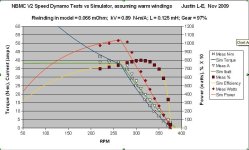
When I do the same comparison between the simulator and geared hub motors, like the eZee and BMC, then the data also fits pretty well, up to the 40-50 N-m that I can test it at. For instance, here is the measured data from my Dynamo with the BMC V2 Speed model hub:

BMC V2 Test vs Simulator.jpg

Not having any first hand data on the planetary gear transmission losses, I just assumed a 97% gearing efficiency for the time being. Because these geared motors have a much lower winding resistance than most direct drive hubs (in this case, just 53 mOhm at room temp, 66mOhm at the end of my testing), the model predicts a staggeringly high stall torque, as there is very little to resist the motor phase current when there is no back-emf. In this particular graph (BMC V2 Spd hub motor, 36.0V power supply, 38A controller) the predicted stall torque is just under 100 N-m. That's a lot, and is certainly pushing the linear 'extrapolation' limit for a small motor like these.

It can be a bit tricky to measure the actual stall torque. In principle, you would think you could just put a force gauge on the end of the wheel and crank the throttle. But in practice, most brushless motor controllers will promptly shut down if they don't experience a commutation after a very short amount of time. As well, the motor phase currents that result are very high and rapidly heat the mosfets, connectors, and other components, so the measurements would be quickly changing over time.

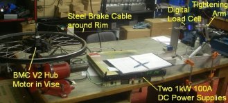
So what I did instead was put a known current through one pair of the phase connectors with a DC power supply. No motor controller involved. A cable was wrapped around the rim of the hub motor, and gradually tugged harder and harder through a load cell until the motor 'cogged' and then flipped to the next position. The peak torque that is measured here should match the torque output with a controller that is delivering the same phase current.

Stall and Saturation Current Test Setup.jpg

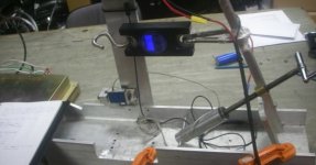
Here is a closeup of the mechanism used for pulling on the cable and measuring the force. It's actually the body of my earlier friction drive dynamo setup, and the arm that originally was used for pressing the EV Warrior friction roller against the tire is now setup to tug on the cable via the hanging load cell.

Load Cell Winch Arm.jpg
 
The results of this experiment are interesting. For the Nine Continent 7 turn winding, I was able to measure the force at 10, 20, 30, 40, 50 and 60 amps. At 60 amps, the insulation on the phase leads was melting off just as I was able to read the force, so that's the highest value that I could test it at. To extend this to 70 amps or greater would require first replacing the phase leads with higher gauge teflon insulated stuff. The data is as follows:

[pre]Amps Force (lb) Torque (N-m)
0 0.2 0.24
10 9.5 11.6
20 17.6 21.5
30 26.3 32.2
40 34.7 42.5
50 42.5 52.0
60 50.6 61.9[/pre]

The inside radius of the rim was 276mm, so that's the value used for the lb thrust -> Nm torque conversion.
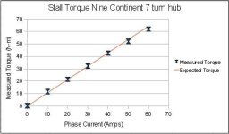
The kV value in the online simulator for the 2807 is 1.07 Nm/A, so we can plot the measured torque above with the predicted value, and the result is this:

NC Hub Stall Torques.jpg

There is maybe a sign that at 60 amps we're starting to see a deviation from linearity, but I wouldn't hold too much faith in this particular datapoint because of the rush with which I had to make the measurement. Otherwise, we can confidently say that the simulator extrapolation right up to 60+ N-m will be bang on.

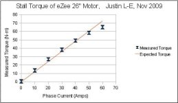
I then repeated this test with the eZee hub motor. Once again, at 60 amps the insulation on the cable going into the hub started melting apart in short order, so that's as far up as it could be tested. In this case though, we see more clearly that the data is deviating at 60 amps and we're into the territory of 2nd order effects:

eZee Stall Torques.jpg

You'll also notice that at the lower currents, the measured torque is actually higher than the predicted torque based on Kv*I. This makes sense as the friction of the planetary gears would get added to the magnetic force when you are tugging on the rim. It occurred to me that this could make for a direct way to measure the gearing efficiency. Put a constant and known current through the phase windings. Then slowly pull on the motor with the load cell at a steady speed and measure the force when the hub is rotating backwards. Then let the motor spin in the forwards direction at a slow steady rate and compare the force this way. The difference in these two force readings should be exactly twice the friction losses from the planetary transmission.

Anyways, the eZee, BMC V1, and BMC V2 appear to have an identical motor on the inside. The magnet size and width, lamination stack, pole count, rotor thicknesses etc. all seem the same. So I would expect their magnetic saturation effects to be identical as well. The difference is that the BMC V2 motors have composite rather than a nylon planet gears, and more importantly to this test, they have a thicker gauge of phase wire going through the axle, so we can pump more current in.

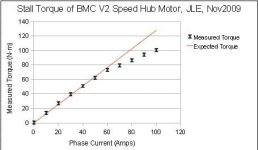
I had to be pretty quick, but I was able to do the same test all the way up to 100 amps, the max of my power supplies. The result shows I suppose what we'd expect.

BMC Stall Torque.jpg

There is very clearly a knee right around 70 Nm, and after this point, the torque increases with more phase current at a lower rate than it does before that point. However, it does continue to increase, and I think most of us would have expected the torque to 'level off' more horizontally.

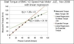
When we do a linear regression to the data beyond the 60A point, we get an incremental motor constant of 0.69 Nm/A, about half what it is in the linear region up to 60A (1.28 Nm/A).

BMC Stall Torque, with curve fit.jpg

The good news here is that it should be possible to model this effect in the simulator with decent accuracy by using a two stage kV. Below 60A it would be 1.28, and above 60A it would be 0.69A + 31.2.

Until then, it means that the simulator results with the eZee and BMC motors should be taken with a grain of salt when the load is more than 60 Newton-metres, but can be assumed quite accurate below that, assuming that the controller doesn't also have a phase current limit in addition to the battery current limit (as I believe the eZee controllers do).

Justin
*********************************************************************************************************
EDIT: The force data above was done on the BMC V2 Torque, model, not the speed model as indicated in the graph titles
 
Justin,

Thanks for posting this and doing all that work.

A quick question: Were these tests all done at full throttle? Ie., with no PWM chopping of the waveform.
I've long wondered whether its at partial throttle that we would be most likely to see deviations from the basic theoretical model. This is because it relies on the parameters of the motor windings at 16 kHz (or whatever the PWM rate is) and harmonics thereof, and I doubt that many motor manufacturers try to control those.

Nick
 
Thanks for these really cool tests, Justin!

Too bad the 9C's phase wires are so small that they start melting at only 60 phase amps... I really thought they could take more than that! I'm pretty sure many people pump much more than that into them, but probably only briefly during accelerations. How long did you have to hold 60A before the wires started melting, BTW? On my higher power setups I upgrade the phase wires to 8/10AWG just after they come out of the axle, which I'm sure helps conduct part of the heat away from the thinner wire in the axle (without actually changing the axle wires which is more complicated).

Do you have any plans to test the 9C's at higher torque levels? One way to get around the melting phase wire issue would be to use a lower RPM/V motor. For example, if you use a 6X10 instead of a 10X6 9C you only need 60% of the phase current for the same torque output. Saturation will happen at a proportionnally lower phase current, but the same torque output.

Pat
 
Tiberius said:
Justin,

Thanks for posting this and doing all that work.

A quick question: Were these tests all done at full throttle? Ie., with no PWM chopping of the waveform.
I've long wondered whether its at partial throttle that we would be most likely to see deviations from the basic theoretical model. This is because it relies on the parameters of the motor windings at 16 kHz (or whatever the PWM rate is) and harmonics thereof, and I doubt that many motor manufacturers try to control those.

Nick

I would find that interesting, too. I know it assumes a theoretical controller resistance and a diode voltage drop to account for r_ds and the free-wheeling diode, but I kind of wonder the appropriateness of the r_ds parameter when it seems that the mosfet's actual average resistance (not including the highest resistance) is much higher during fet switching during PWM than what the r_ds parameter would suggest.

Anyways, very interesting tests! It seems the phase currents of the hub motor goes somewhere shortly above 38 Amps during the tests (I'd guess 60-70 A). I would wonder if it would also show linear-deviating affects at higher phase currents similar to the BMC motor, as you might encounter on a relatively steep hill.

Also, it's interesting the BMC's motor's torque doesn't flatten as you'd expect a limiting factor to impose, it just seems to change slope. I wonder what would account for that? Usually, 2nd order affects are non-linear and that's how they 'out-grow' the main linear effects.
 
Tiberius said:
Justin,

Thanks for posting this and doing all that work.

A quick question: Were these tests all done at full throttle? Ie., with no PWM chopping of the waveform.

They Dynamo tests were all done at full throttle, yes. However, you can see when the current limit of the controller kicks in at ~38A, and then the controller is doing PWM to maintain constant input power. That happens at the peak power point on the graph where all the curves have inflection points and change shapes. The data matches the model even in the PWM region surprisingly well.

The saturation current tests didn't involve a controller or throttle at all, just pure DC power supply.

I've long wondered whether its at partial throttle that we would be most likely to see deviations from the basic theoretical model. This is because it relies on the parameters of the motor windings at 16 kHz (or whatever the PWM rate is) and harmonics thereof, and I doubt that many motor manufacturers try to control those.

It is a good question, and so far I've been able to see it doesn't appear that the effective motor parameters change any notable amount when fed a switching drive waveform. I could repeat the dynamo test above using a lower current 20A controller, then the bulk of the curve would be in the PWM limited mode and we'd be able to see this over a longer stretch.

Justin
 
justin_le said:
I've long wondered whether its at partial throttle that we would be most likely to see deviations from the basic theoretical model. This is because it relies on the parameters of the motor windings at 16 kHz (or whatever the PWM rate is) and harmonics thereof, and I doubt that many motor manufacturers try to control those.

It is a good question, and so far I've been able to see it doesn't appear that the effective motor parameters change any notable amount when fed a switching drive waveform. I could repeat the dynamo test above using a lower current 20A controller, then the bulk of the curve would be in the PWM limited mode and we'd be able to see this over a longer stretch.

Justin

Thanks Justin,

If the winding inductance is sufficient, then applying a PWM voltage waveform still results in a steady (or nearly steady) current. I was concerned about creating other losses if the inductance isn't perfect - eg, eddy current losses in the laminations appearing as a resistive element at 16 kHz but not at the commutation rate. Rather than try to measure these by looking for the effects on the motor dynamics, it might be easier to measure the loss tangent of the winding directly. Unfortunately my test gear for doing that doesn't go down below 300 kHz, so it would mean rigging up something special.

Here's another thought. As the "DC" current in the windings gets to the point where things start to be non-linear, presumably the inductance of the winding drops. Does it drop sufficiently to upset the PWM process? In that case you might actually see a significant difference in the motor dynamics between direct drive and PWM drive.

There are also the effects in the controller that swbluto described.

Nick
 
Tiberius said:
If the winding inductance is sufficient, then applying a PWM voltage waveform still results in a steady (or nearly steady) current. I was concerned about creating other losses if the inductance isn't perfect - eg, eddy current losses in the laminations appearing as a resistive element at 16 kHz but not at the commutation rate. Rather than try to measure these by looking for the effects on the motor dynamics, it might be easier to measure the loss tangent of the winding directly. Unfortunately my test gear for doing that doesn't go down below 300 kHz, so it would mean rigging up something special.

I think we could answer that with a basic variable frequency LCR meter on one of the phase windings no, and compare the DC resistance with the effective resistance it shows at 16 KHz ? I don't have a lab grade LCR meter at the moment, but this might be justification for buying one if that's all it takes.

Here's another thought. As the "DC" current in the windings gets to the point where things start to be non-linear, presumably the inductance of the winding drops. Does it drop sufficiently to upset the PWM process? In that case you might actually see a significant difference in the motor dynamics between direct drive and PWM drive.

Ah I see what your are getting at here. So if the 'knee' region I found above with the BMC hub correlates to the iron saturating, then the incremental winding inductance would be way lower and we'd expect to see much high current ripple, and associated losses?
Someone could test this without too much difficulty by installing a high amperage/high bandwidth hall effect current sensor on one of the 3 phase leads and directly looking at the current ripple of a nearly stalled hub.

In any case, in the model I'm using for the simulator right now, the winding inductance is only used in so much as it effects the commutation, and not in any way related to PWM frequencies (which are entirely ignored). It's an interesting process that goes on in the commutation of a BLDC motor when one phase is switched to high impedance mode and a new phase is turned on. Even if the controller isn't doing PWM you still end up with a higher motor current than battery current from the energy that is stored in the winding inductance at each commutation event.

-Justin
 
Huge respect to you Justin! This is some very cool stuff! I love seeing predicted values compared with tested values.

It would be fantastic to get an idea of the current at which a 9C motor saturates. For just doing a bench test, popping off a cover, drilling a cooling hole, and passing some 8awg phase wires through should do the trick with minimal effort.
 
Very big thanks for recording and sharing all that data. All quite interesting! I have always wondered how fast the lamination on these motors would saturate, as they seem to be low quality on the whole. It would be quite expensive to have such a large silicon steel lamination stack!

Do you have any bafang motors to test?
 
Justin,

I'll chime in with the praise for the excellent engineering work. UBC should be proud of such graduates. I like the way you reused the old dyno setup.
dynamo.jpg
into your stall torque measurement setup:
file.php


Am I understanding it right that you slowly wind up the force, then read the force just before the motor jumps one EM "cog"? Isn't that hard to do manually? Or does the meter record peak force?

I was suprised to see that the 9C is such a good performer. Looks like BMC's main advantage is the lighter 4kg instead of 6kg, not so much the torque.

Would you being able to put 100A into the BMC and 60A into the 9C suggest that the BMC can take a bit more current and power sustained also? I had first, but perhaps erroneously assumed that the bigger 9C would be better at higher power, but the lower R of the BMC and comparable kV should let the BMC make more output power before reaching a thermal limit, right?

I guess what is missing is a good thermal model of the motors. I've done FEM models of different shaped solid materials, but I don't know how to deal with the motor air gap in the 9C. Google searches were also not helpful yet. (Only found a ref to some French INRIA paper I would have to pay for and can't read anyway). The BMC would be an even greater challenge with its many internal parts.

Alternatively a thermal model could also be experimentally measured I think. Maybe with one thermometer on the windings and one on the outer casing. Can do transient parameters by starting cold and dumping say 100W heat into windings, then measure both temp rise curves.

Martin

PS: Would love to see a picture of your new 40nm dyno also.
 
jag said:
I was suprised to see that the 9C is such a good performer. Looks like BMC's main advantage is the lighter 4kg instead of 6kg, not so much the torque.

Would you being able to put 100A into the BMC and 60A into the 9C suggest that the BMC can take a bit more current and power sustained also? I had first, but perhaps erroneously assumed that the bigger 9C would be better at higher power, but the lower R of the BMC and comparable kV should let the BMC make more output power before reaching a thermal limit, right?
Justin's tests seem to be telling us that the 9C can produce more torque before going into magnetic saturation. As the motor saturates, it produces less magnetic flux per amp, so efficiency drops rapidly as this happens. Since power is torque times speed, we can conclude that the 9C stays efficient to higher power levels than the BMC, but we don't know how much yet because of the phase wires melting on the 9C.


By the way, does anyone know what the stock phase wires of the 9C's are insulated with? They are about 14 gauge (0.070" dia), and look to be made of teflon-looking material, but nothing's writen on them.
 
ZapPat said:
jag said:
I was suprised to see that the 9C is such a good performer. Looks like BMC's main advantage is the lighter 4kg instead of 6kg, not so much the torque.

Would you being able to put 100A into the BMC and 60A into the 9C suggest that the BMC can take a bit more current and power sustained also? I had first, but perhaps erroneously assumed that the bigger 9C would be better at higher power, but the lower R of the BMC and comparable kV should let the BMC make more output power before reaching a thermal limit, right?
Justin's tests seem to be telling us that the 9C can produce more torque before going into magnetic saturation. As the motor saturates, it produces less magnetic flux per amp, so efficiency drops rapidly as this happens. Since power is torque times speed, we can conclude that the 9C stays efficient to higher power levels than the BMC, but we don't know how much yet because of the phase wires melting on the 9C.

I was thinking that the main limit at 60A or thereabouts is the ability to dissipate the thermal waste heat.
Just from internal resistance the contribution is:
BMC V2T: 60^2*.1 = 360W
9C 2807 : 60^2*.23 = 828W
I hadn't paid attention to the low internal resistance of the BMC V2T before.
9C wasn't measured beyond 60A, but even if kV drops less than BMC, I was wondering if BMC would not still be the better choice for high power.
 
I would say the BMC gears will break faster than the 9c will saturate. Busted my BMC on 72v really fast, although it was crazy powerful. 9c is still rocking solid after a few hundred miles.
 
johnrobholmes said:
I would say the BMC gears will break faster than the 9c will saturate. Busted my BMC on 72v really fast, although it was crazy powerful. 9c is still rocking solid after a few hundred miles.

Were those MAC plastic gears (V1 400W) or the BMC composite gears (V2 600W) ?
 
Probably just the plastic gears. I will say the geared motor accelerated and climbed hills better. As to be expected from a lower resistance motor.
 
Justin,

concerning your Dynamo type Dynamometer. how did you calibrate the output of the Dynamos? do they feed a fixed load? or is there some kind of variable load?

rick
 
johnrobholmes said:
Do you have any bafang motors to test?

Nope. If someone wants to donate one to the cause so that it can be characterized and modeled and put on the simulator I will do that, but I would have to keep it on hand here in case I ever wanted to do additional testing or verifications.

Justin
 
ZapPat said:
Thanks for these really cool tests, Justin!

Too bad the 9C's phase wires are so small that they start melting at only 60 phase amps... I really thought they could take more than that! I'm pretty sure many people pump much more than that into them, but probably only briefly during accelerations. How long did you have to hold 60A before the wires started melting, BTW?

It was about 20-30 seconds. The insulation immediately over the phase wires actually seemed to hold up OK, but the black sheath that covers all the wires was melting away, so that seems to be of lower temp plastic.

Do you have any plans to test the 9C's at higher torque levels? One way to get around the melting phase wire issue would be to use a lower RPM/V motor. For example, if you use a 6X10 instead of a 10X6 9C you only need 60% of the phase current for the same torque output. Saturation will happen at a proportionnally lower phase current, but the same torque output.
Pat

Yeah, I was actually just about to order a 10 turn winding for this, but then I realized that I won't have enough voltage! I have one 10V 100A supply, and the other is 8V 125A, so max I can do is 18V 100A. I suspect that the 10 turn winding is about 0.42 ohms, so at 18V that'd be just over 40 amps that would go through, which is basically equivalent to the 60A I had in the 9x7.

Anyways, I do plan on trying to find the saturation point in both the 9C and the Crystalyte 400 and 5300 motors. I will do as suggested and drill a hole in the NC side cover and feed 10-12 AWG wire directly to the windings and repeat the test up to 100A that way. Not sure when but will post the results here once done. Justin
 
I love your work here Justin! You're a huge asset to the EV revolution. :)


Yesterday I fit 10awg wires into my 9C hub through the axle. It didn't take much time. Drilling the side cover would be faster by a bit, but this really was quite simple, and you wouldn't need to take it apart again to use the hub afterwards.

http://endless-sphere.com/forums/viewtopic.php?f=2&t=14580
 
jag said:
Justin,

I'll chime in with the praise for the excellent engineering work. UBC should be proud of such graduates. I like the way you reused the old dyno setup. into your stall torque measurement setup:

Ha. Well I first wasted a huge amount of time searching everywhere around the shop and garage for a small winch that could be used before realizing there was a solution right in front of me.

Am I understanding it right that you slowly wind up the force, then read the force just before the motor jumps one EM "cog"? Isn't that hard to do manually? Or does the meter record peak force?

You are right that it was a bit tricky to do manually. The hanging load cell doesn't have a peak force recorder, so I have to pull slowly enough that the scale is only incrementing by one digit at a time in order to see what the actual max reaches. For most of the tests I repeated the measurement 4-5 times and took the average, but at the really high currents it needed ~10 minutes for the lead wires to cool down each time so I only did 1 or 2.

Would you being able to put 100A into the BMC and 60A into the 9C suggest that the BMC can take a bit more current and power sustained also? I had first, but perhaps erroneously assumed that the bigger 9C would be better at higher power, but the lower R of the BMC and comparable kV should let the BMC make more output power before reaching a thermal limit, right?

Super good question. The geared motors definitely have lower resistance for the same K value as direct drive, which means less heat generation. But they also have much less thermal mass, and their magnets are not thermally coupled to the casing as with a direct drive hub, but are instead sandwiched with a cushion or air on either side. So the thermal limit of the BMC/eZee motors would be hit at a lower wattage too.

I guess what is missing is a good thermal model of the motors. I've done FEM models of different shaped solid materials, but I don't know how to deal with the motor air gap in the 9C. Google searches were also not helpful yet. (Only found a ref to some French INRIA paper I would have to pay for and can't read anyway). The BMC would be an even greater challenge with its many internal parts.

Screw FEM models, lets do some test!

When I was doing the saturation current experiments on the eZee hub I though I was seeing slightly higher readings when the windings were cool than if I repeated tests in quick succession when they remained warm. So I decided to see if there was a significant thermal issue that I'd have to isolate as well (and was praying not, since that would make the whole saturation current testing procedure take wayyy longer with a long motor cool-down period after each measurement).

The situation was that I put exactly 30 amps through one of the phase leads of the eZee hub. Every 2-3 minutes I measured both the force in pounds required to make the hub 'cog', as well as the voltage drop across the power supply, from which we could infer the winding temperature based on copper's pretty high temp coefficient of resistance. The raw data looked like this:

[pre]Time(m) Amps Volts Force1 Force2
0 30 4
0.75 30 4.15 31.2 31.8
2.5 30 4.7 29.8 31.4
4.25 30 5.05 31.8 30.2
7.5 30 5.3 30.6 31.6
10 30 5.5 31.2 31.2
12.5 30 5.7 30.2 30.8
14.75 30 5.9 30.4 30.2
17.5 30 6.1 30 30
19.5 30 6.25 30.2 29.4
22 30 6.4 29 30.6
24.5 30 6.5 29.4 28.8
27 30 6.65 29.2 29.2
30 30 6.8 28.8 28.2
33 30 6.95 28.2 28.6
36 30 7.05 27.4 28.2
39 30 7.15 28 27.4
42 30 7.25 27.2 26.8
45 30 7.3 25.8 25.4[/pre]

At this point, after 45 minutes of running a continuous 30 amps into an eZee hub, I could see that the torque was starting to plummet fast, meaning that the rare earth was demagnetizing, and the smell of "somethin' cooking" started to hang in the air.

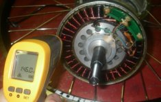
I had to let the motor sit for about 10 minutes before I could even handle it to open up since it was too hot to touch. When I did get the side cover off, white fumes emerged for a few minutes. The windings were definitely darkened, but not burnt to a crisp. The grease in the ball bearings had fully liquefied and some of it vapourized. About 20 minutes after I stopped the test I finally got an IR thermometer on the windings and they were still nearly 150 degrees C.

Cooked Winding.jpg

Assuming that the linear resistance / temperature relationship with copper holds up even over two hundred degrees, then we can infer the approximate winding and lead wire temperature easily enough from the voltage drop across the power supply. Doing that, and averaging the two force measurements into a torque value, the data looks graphically like this:


So for the first 10 minutes or so, there was basically no effect that the heating had on the output torque of the magnets. But then from about 10 minutes to 40 minutes, there was a pretty steady decline, starting at 38 N-m and falling to about 34 N-m. This as the winding temperature reached over 200 Celsius. Just after this point, it seemed that the torque was about to fall quite a bit more rapidly, which coincided with things starting to burn up on the inside, so I shut off the supply not wanting to destroy the hub completely.

After the motor had cooled, I repeated the torque test at 30 amps and it had recovered to about 35 N-m. Which is good, but almost 10% less than it was before the experiment. So certainly a temperature excursion like this causes some level of permanent demagnetization. Now I have a particular eZee motor runs 10% faster than all the rest!

From this data, it shouldn't be too hard to extract some kind of a thermal model for these geared hubs in their static, non-spinning situation.

I'll try to repeat the same test with a Nine Continent hub, putting whatever current is required to have the same 38 N-m of torque and then see how long it takes for the motor to get so hot that the magnets start to demagnetize. Then we'll know which of the two hub designs hits the thermal limit first. Anyone wagering bets?
 
You do really good work Justin! I'm extremely impressed with everything I've seen from you.

I predict over this long of a test period, the double airgap of the geared motor with this low of an energy input rate will internally hold temps with a fairly small delta-T between coils and internal rotor. In other words, dispite the less direct thermal conduction design, I would model the inside of the hub as a thermodynamic closed system, and focus on surface area and coatings of the outside surface.

I know the 9c's I've got were bathed in a thick black paint blanket. The increased thermal insulation value NEVER balances the increase in IR radiated energy from the black color at temps below any magnets currie point. lol

If they are roughly the same size/shape, and the geared hub has bare aluminum covers, and they are both taking in the same amount of power, I would give the win to the geared hub.

Otherwise, it's going to depend on which hub requires higher input power to meet the required torque value. :)
 
justin_le said:
johnrobholmes said:
Do you have any bafang motors to test?

Nope. If someone wants to donate one to the cause so that it can be characterized and modeled and put on the simulator I will do that, but I would have to keep it on hand here in case I ever wanted to do additional testing or verifications.

Justin

Great work Justin! I am curious as to why you don't stock Bafang motors as they are quite well respected, perhaps more in Europe, where power and speed is more restricted, than in America.
 
justin_le said:
I'll try to repeat the same test with a Nine Continent hub, putting whatever current is required to have the same 38 N-m of torque and then see how long it takes for the motor to get so hot that the magnets start to demagnetize. Then we'll know which of the two hub designs hits the thermal limit first. Anyone wagering bets?

Assuming you use a 7 turn hub I'm betting it'll be ~34amps and it'll take 36 minutes to cook the same as the EZ.

*EDIT* unless you use only 1 power supply- then I bet you run out of voltage and have to drop the current giving the 9C the win!
 
Back
Top