Infineon programming cable question (non Prolific chipset)

matt_in_mtl

100 mW
Joined
Aug 13, 2008
Messages
49
Hi,
I have just bought a 48V EB206 6-fet Infineon controller, and I am trying to program it. I have a USB-TTL serial cable, and I soldered in a connector like this:
file.php

however I have not had luck programming. I am using a USB-TTL converter that uses FTDI chipset. The software runs fine (doesn't complain), and I can see '888888888' being output when I try to flash the controller, but nothing happens. I have followed the directions at
http://endless-sphere.com/forums/viewtopic.php?f=16&t=14836&p=220949
and
http://endless-sphere.com/forums/viewtopic.php?f=2&t=13139&start=15
including making sure that I plug it in so it gets power before tx/rx, and also connecting ground after the other pins have been plugged in.
So, has anyone had any success using a non-Prolific/Cygnal USB-TTL converter? Or is there maybe some special capability of the Prolific chip they are using? Is there somewhere I can pick one up cheap?

Thanks for any help :D

-Matt
 
i have used a USB adapter using the same chip as yours. i added a momentary switch to it as in the picture below:


http://www.ebike.biz/infineon.htm

has excellent directions how to do the flash. it worked for me.

rick
 
Mike1 said:
Matt, did you do the Hyperterminal test?
Yes I did the hyperterminal test. I have also used this same cable for communicating with other uC's so I know it works. I saw in another post something about making sure that some of the unused serial signals were grounded. Do you guys know anything about that? I only saw it mentioned in one place.

Also rkosiorek, I have the newer (EB206) 6-fet controller so it has a 6-pin programming header. I understand that 2 of these pins need to be connected to 5V when programming, and they are in a different order than in your image above.

Last night I powered up the controller and can confirm that it works, so I suspect that it is some issue with my method, not with the hardware.

-Matt
 
Are you trying to program it with the throttle and motor hall wires connected? This can pull the 5V line down and prevent it working.
Sometimes the 5V can be pulled too low without these connected.
 
Mike1 said:
Are you trying to program it with the throttle and motor hall wires connected? This can pull the 5V line down and prevent it working.
Sometimes the 5V can be pulled too low without these connected.

I actually didn't have anything connected to it (except the programming cable)). That is a good point though, next time I will check to make sure I am getting full 5V.
 
I got a 9 fet infineon controller from Edward Lyen and it has a similar 6 hole layout on the board for the PC interface. I'm about to wire it up but I have a couple questions.

Where did you get your pinout info from? Are the Tx & Rx labels with respect to the controller or the PC? By that I mean that Tx (transmit) at the controller end ought to connect to Rx (receive) at the PC end and vice versa. Second, I'm wondering about the two +5v pins. If I understand this right, the controller is not to be powered up via its power leads to a battery, but will instead be pulling its power from the PC's USB port. The USB has a single +5v line. Should that one line be connected to both of these pins/holes on the board? I wonder why they didn't just bridge the traces. Is there ever a scenario where one would get a different voltage, say +3 v or +12 v?
 
What board type is it? EB209 or EB809? I'll assume 209 as you mention the two 5V pins.

The TX and RX refer to the PC end if you use the layout detailed in the 18 fet thread.
 
Mike1, yes, it's an EB209. Thanks for the clarification on the Tx & Rx. Should I be bridging the two +5 v holes?
 
hi
matt_in_mtl can you help me with something.
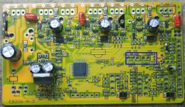
You have already taken some pictures of your circuit board, have you got one of the area where the reverse wires are soldered to the board one should go to ground the other to X3, it is the X3 from the component side I am interested in, look on your board where i have put a blue box in the picture below.
6 fet low res.jpg
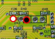
in the closup below the wire is probably attached in one of the two marked pads it would be usefull to see a picture of that area of the board.
closeup x1 to x3.jpg
this should solve a problem that has buged me for some time.

thankyou Geoff
 
SpeedEBikes said:
Mike1, yes, it's an EB209. Thanks for the clarification on the Tx & Rx. Should I be bridging the two +5 v holes?

Yes the two 5V holes need to be bridged during programming. I know some people have bridged them permanently but I figure there must be some reason why they are separate as standard.
 
Hi
if you link them permanently then I hav found problems can happen.
I had faults happen with linked +5v but I can't remember what they were I just changed to unlinked +5v.

Geoff
 
Geoff,
unfortunately I didn't take any pictures of my controller PCB. The pic I posted was one that someone had already posted. If I have the controller apart again, I will try to remember to snap some pics.
-Matt
 
geoff57 said:
Hi
if you link them permanently then I hav found problems can happen.
I had faults happen with linked +5v but I can't remember what they were I just changed to unlinked +5v.

Geoff

I would guess that it powers up circuits that aren't normally used and increases the load on the regulator components which we know can run hot at the best of times.
 
Thanks. I had gone ahead and soldered the two together, but I'll undo that and use an external switch or connector.


Mike1 said:
geoff57 said:
Hi
if you link them permanently then I hav found problems can happen.
I had faults happen with linked +5v but I can't remember what they were I just changed to unlinked +5v.

Geoff

I would guess that it powers up circuits that aren't normally used and increases the load on the regulator components which we know can run hot at the best of times.
 
WOOT! I got it to programe :lol: So, what was it? Something dumb actually. I made a mistake in the cicuit and was not getting the 5V line. After fixing that, and adding a momentary switch in the 5V line it worked like a charm. So.. all down to my own thick-headed-ness.

Unfortunately I am still having an issue with the controller cutting out after I give it a little throttle, I suspect it is hall related and will be scoping it this weekend.

-Matt
 
Matt, nice to hear you got it sorted. I've run two different types of modified outrunner on the newer 6 FET 116 controllers now and both worked fine, with no sign of any hesitation or cutting out when the throttle's wound on full. I mod my motors by just fitting the Halls at 120 deg on the 12 slot stator, in the slots. It's not perfect, but is pretty easy to do once you get the knack and seems to give pretty good results.

Jeremy
 
Matt where did your controller come from?

on the point of the throttle cutting there could be two things causing the fault.

One is in the programming I have had a couple of cases of reprogramming a controller then loosing all throttle use like you have done worse for me as i did it in town while testing with my notebook computer(nothing wrong with the computer) there is only one soloution to this problem dump the .ASV file after you look what the settings are then copy the settings into a fresh .asv fileand save that remember NO spaces use underscore or dash instead, for some reson spaces are not liked a file save with a space will not be retrevable again. After saving the file send it to the controller this should cure the problem 90%.

there is also a throttle problem when gunning the throttle, if you gun the throttle the motor cuts then you cut the throttle and in a few seconds twist the throttle more gently, I have observed this problem with the 12 fet controllers the problem was solved in the mini monster thread by putting in a 1000uF capasitor in place of the 470uF.
hope this all helps.

Geoff
 
Matt is having the same problems that I was having with 2 new 6fet controllers ( do the 116 controller only use the newer software to program i.e 206 ) , I think Matt is already running 120 deg in the slots. The problems went away for me when I switched to 17.14 deg from 60 deg but had no problems at all with the newer 12 fet controller (212) :|
 
I suspect my problem is still to do with the halls. Do any of you guys have a trouble code led wired to the board? Did I understand correctly that there is one? I have one on connected to the LED/ diagnostic signal on the schematic (connects to R28). It turns on when I get 5V, but doesn't seem to give any kind of diagnostics.

gwhy! I have built a 17.14deg spaced hall bracket with the halls external to the motor, and that seemed to help a bit, but the problem is still there. I am using A3340 sensors, I will be scoping their signals tonight to see if I am getting bad signals. I was hoping that the diagnostic LED would blink and give me some feedback that it was the halls.

-Matt
 
So, before I scoped my hall signals, I tried running the controller off of one of my 6S packs, and it works fine! I was able to ride the bike under its own power. The belt drive was slipping and I only got up to 15km/hr but it was still sweet! :D So, the issue seems to be with the controller.
geoff57 said:
Matt where did your controller come from?

there is also a throttle problem when gunning the throttle, if you gun the throttle the motor cuts then you cut the throttle and in a few seconds twist the throttle more gently, I have observed this problem with the 12 fet controllers the problem was solved in the mini monster thread by putting in a 1000uF capasitor in place of the 470uF.
hope this all helps.
Geoff

I wonder if this may be the issue? I know my controller only has a 470uF cap. What size cap do you have gwhy!? Also, what voltage do you run?
 
Hi Matt,
When I was having all the problems with mine I did strap a 1000uf cap across the original cap (470uf) And this didn't resolve the problem for me ( but it is well worth trying ). I am running 48v my lvc is set to the lowest setting as I have a alarm fitted to the battery instead. My battery leads are only about 10 inches long into the controller and phase wires are about 6inches long the hall wires are also about 6 inches long and all twisted togeather, Im not saying this is why mine works but if your battery leads are a lot longer this may not help so the extra cap may well solve it. I assume you have tweeked around with the timing to see if this helps :?: . My 12fet controller had no problems at all and worked from day 1.. its a bit strange :?
 
Hi,
I have the a new EB206 and am trying to set up the programing. I think my USB-TTL is faulty, computer not seeing it.
I am using a USB-TTL converter that uses FTDI chipset, should my computer see this as 'new hardware' when I plug it in, any other USB device I plug in does.
Can I try something to check it?
Thanks Eddie
 
electraflyit said:
Hi,
I have the a new EB206 and am trying to set up the programing. I think my USB-TTL is faulty, computer not seeing it.
I am using a USB-TTL converter that uses FTDI chipset, should my computer see this as 'new hardware' when I plug it in, any other USB device I plug in does.
Can I try something to check it?
Thanks Eddie

When you plug in the USB-TTL adapter, if it is properly installed it should create a new COM port This will show up under ports in the device manager. To get there go:
Right–click My Computer, click Manage, and then click Device Manager
If a new port is created, make note of it's number since this is what you will have to enter into the parameter setting software.

-Matt
 
electraflyit said:
Hi,
I have the a new EB206 and am trying to set up the programing. I think my USB-TTL is faulty, computer not seeing it.
I am using a USB-TTL converter that uses FTDI chipset, should my computer see this as 'new hardware' when I plug it in, any other USB device I plug in does.
Can I try something to check it?
Thanks Eddie

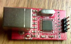
Im not sure about your usb-ttl converter but the one I bought had the same problem at first and this was due to there being a option to fit a switch so there were two very small pads on the converter that needed to be joined together this then solve my problem. Do you have a picture of your converter it may well be the same as mine. Hangon I will take a picy of mine. Ok sorry about the quality of the pic but hope this helps.
usb_adaptor.jpg
 
Back
Top