DIY Dyno

Jeremy Harris

100 MW
Joined
Oct 23, 2007
Messages
4,208
Location
Salisbury, UK
Whilst developing the simple BLDC controller, I've found that I needed to load the test motor predictably to see how the controller stands up to conditions like high torque, low RPM and make sure that the current limiting and controller protection circuit works properly. I was originally just going to make a simple brake to load the motor, but realised that it needed to be a bit more complex if I was going to be able to make even quite simple measurements of motor load/performance. This has led to me making a pretty universal dyno to test motors up to about 10Nm or so of torque and around 12,000 rpm maximum (equivalent to maybe 12.5kW maximum).

The start of this project is here, in the controller thread: http://endless-sphere.com/forums/viewtopic.php?f=2&t=23350&start=180#p347481 but as it now seems to be a universal dyno, rather than just something to test the controller, I felt it deserved its own build thread.

First I made up a brake, using a 120mm diameter disc brake with the calliper fitted to a free floating reaction arm, pivoted on the motor shaft:
Disc brake.JPG

Having made this, I needed a way to measure the torque reaction on the calliper arm, so I made up a small load cell:
Home made load cell.JPG

This has a full scale range of about 110N, so when fitted 100mm from the shaft centre it will measure up to about 11Nm of torque. It will screw into a pillar bolted to the dyno base plate, with the calliper reaction arm resting on the ball bearing pressed into hole on the top of the load cell.

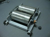
Having made the load cell and tested it, I realised that it would be more useful to have a stand-alone dyno that could be coupled to any motor fairly easily. It wouldn't be much more work to make a proper dyno, and would be far more useful as a bit of workshop kit. This meant machining up some alloy plate to form a frame, into which will be fitted a pair of flange bearings at either side, to support a 12mm diameter shaft that will carry the disc brake and calliper:
Dyno frame.JPG

I still need to bore the side plates for the bearings and make up some brackets to hold things, but it's getting there.

Having decided that a stand-alone dyno would be useful, I then realised that having an integral display that shows RPM, torque and motor power would be useful, particularly if the unit could also hook up to a serial port and stream ASCII data to a PC. The load cell needed an amplifier, and it looks easy enough to measure rpm with a sensor fitted close to the disc. The disc already has 12 slots in it, so a slotted opto switch will work a treat to give rpm with decent resolution. Add a small Picaxe 08M microcontroller and a serial display and I have all the ingredients for a simple bench dyno:
Electronics and display.JPG

Tomorrow should see the side plates machined up, mountings for the load cell made and a plate to hold the display and electronics. The whole lot will run for hours from a small PP3 9V battery, so no power supply will be needed. If this all works, then I should be able to get some fairly definitive data on motor performance. Might be useful when it comes to looking at things like Burties timing adjuster, as well as the effect of different motor winds.

Jeremy
 
Can you go into a bit more detail about the load cell amp? That is where I am stuck on my dyno. I can shell out big cash for one, but I am wanting to learn more than just buy.
 
johnrobholmes said:
Can you go into a bit more detail about the load cell amp? That is where I am stuck on my dyno. I can shell out big cash for one, but I am wanting to learn more than just buy.

Sure, but I just nicked the idea from someone else............ :) (as a Canadian friend of mine says, that's just "R & D" - "Rip-off and Duplicate")

The load cell itself is very simple and fairly linear. I've used the same basic split ring design several times and found them fairly easy to make and give reliable results. The basic idea for the load cell and the amplifier came from an amateur rocketry site, where a chap wanted to measure thrust from home made rocket motors. Here's a link to the site: http://www.nakka-rocketry.net/

The load cell design is made easier by using the Excel calculator that's on that website: http://www.nakka-rocketry.net/strainlc.html (the download is towards the bottom of that page). I've found that it's hard to get low load ranges using the basic configuration on that web site, but the basic formula holds for any split ring type design, so it's possible to machine up rings on a lathe to the right dimensions. I always use two strain gauges, one inside the ring and one outside, arranged as a half bridge, as this gives better results I've found. I also bond two 120 ohm 1% metal film resistors to the cell to make the dummy half bridge, as that provides reasonably good temperature compensation. There is a good PDF showing how to mount strain gauges here: http://www.nakka-rocketry.net/articles/Gages.PDF

The amplifier is simple, yet works very well in my experience. It uses an INA122 instrumentation amp IC that is probably one of the easiest there is to use for this job. Mine runs from the 5V supply that powers the micro-controller and has enough gain to increase the ~ 8mV full scale from the strain gauges to around 4V for the A/D input on the Picaxe chip. The circuit I used is similar to the one under the Excel download on the link above, but with a single supply and with the strain gauges wired differently (in my circuit I have one amp input fed from the junction of the two strain gauges, the other from the reference junction from the two resistors). Because I use a single supply, I have to juggle the wires around to get a + offset and allow the circuit to work, after I've built it. This is because there's a 50/50 chance that the offset from the tolerances of the resistors and strain gauges will be such as to make the amp output try and drive below zero. It's easy to just swap the wires around to get a small positive offset voltage, and then take this out using an auto zero routine in software.

I've made around four or five load cells using the method on that web site and they've all worked well. This is the first time I've made such a low load version, using a ring rather than a hole drilled in a bit of alloy plate, but so far it looks to be as good as all the others.

Jeremy
 
I managed to get a few more hours work done on the dyno today, in between spending two hours making a plate to fit a spare chuck on to my rotary table, just so I could make one of the parts for it...........

I've almost finished the frame, I just need to add the motor mounting bracket and fit the pillars that hold the load cell and the rpm sensor. Here's what it looks like at the moment, with the load cell just resting in place:
Dyno frame with shaft.JPG

I decided to make a dedicated trigger wheel for the rpm sensor and to use a slotted Hall switch rather than optos, as I happened to have a couple lying around. This is what took the extra time, as up to now I've not had a need to mount a spare chuck I have to the rotary table. I needed to do this to mill out the slots in the steel disc (which are now slightly magnetised and are picking up swarf............). This is the sensor disc fitted to the dyno shaft, next to the brake disc:
View attachment 1

Because I now want this to be a universal electric motor dyno, I decided to fit a rubber coupling to the shaft. This will allow for small amounts of misalignment between the motor shaft and the dyno shaft, plus, by having a range of half couplings bored to different sizes it means that I can quickly swap motors over. This is the type of coupling, there is a cross shaped bit of rubber that fits between the jaws and couples to the other identical half on the motor shaft:


Tomorrow I should be able to get all the mechanical stuff finished, so I can crack on and get the electronics working. I'm still waiting for 12 LiPos to arrive from HK, so I'll probably start off testing with the small re-wound Towerpro 5330. A big roll of 1.5mm diameter enamelled wire arrived yesterday, so if I'm feeling masochistic I could do some motor stator winding.

Jeremy
 
Great Work!

I follow any update on this Jeremy.

Doc

BTW.. Happy New year!

Doc
 
Great job!

It will be interesting to see how well the disc brake can be modulated for different loads as it gets hot, and whether the heat generated by it has much impact on your load cell. I expect the disc will get red hot if your running it at a continuous 12 kW load for long. I did some googling and found a 12.5 kW Thermal Capacity Tension Control Multi-Caliper Disc Brake for $827 that uses a 10x2" rotor with a max rpm of 4000 and up to 5 pneumatic calipers (51 or 88 Nm each) for up to 440 Nm of torque depending on caliper number and pad coefficient used. Going by this, you'd need a 10x2" rotor if you want to handle your 12.5 kW continuously, or maybe some water mist and a big fan.

Also, none of the Nexen rotors are rated higher than 4000rpm. If your going to run 12,000 rpm, I'd want a nice cage around that disc, and ventilation/cooling to suck away any pad dust.

Even this small 475rpm 1.36 HP engine gets its Prony brake hot in a short period of time.

[youtube]9Wi51Kf8bzA[/youtube]
[youtube]weJhTdnlUAo[/youtube]
 
Thanks for the supportive words, folks.

Well, I did some initial testing of the brake today, just spinning it up with the lathe, and it'd not really good enough for the job. The issue isn't so much heat or the ability of the disc brake to apply enough load, it's controllability. The brake produces masses of low speed torque, but once you spin it up over 2000 rpm it gets near-impossible to accurately set the required braking force. My guess is that disc brakes aren't really cut-out for working at high rpm, as the slightest variation in brake pad pressure, just from the inherent small run out on the disc, or temperature changes, make the thing wildly change the brake load.

I can see I'm going to have to switch to a different kind of brake. I'm looking at several options, all based on eddy current braking. I'd prefer a non-power driven solution, so an alloy disc with some neo magnets mounted to a movable frame that slots down over the disc, such that I can vary the area of the disc exposed to the magnetic field seems like a reasonable way forward. Using a 120mm alloy disc, maybe 6mm thick, with some decent neo magnets should give me around half a Tesla or so in the gap, I think. A rough calculation of the eddy current losses seems to show that I can probably get enough power absorption from three or four magnet pairs mounted so that I can move them in and out relative to the edge of the disc. The disc will get hot, but a quick proof of principle test that I've just done with an alloy disc spun up in the lathe with a couple of old hard drive magnets held either side seems to show that this will work OK.

The major advantage of the eddy current brake is that it's not going to be affected much by temperature changes or the friction coefficient changes that make the disc brake unworkable. The small disc that I span up in the lathe got hot, but the brake load seemed to stay the same. The other advantage is that this type of brake applies an increasing load with rpm, making it better in some respects when testing across wide rpm range.

I'm not too worried about the heat load, as I don't need to keep the thing running for long when making measurements, particularly if I just stream the data to the PC. A complete motor run at full throttle, from zero torque to maximum torque, shouldn't take more than half a minute, at most. Assuming that the 6mm disc starts at 20 deg C and that the average power absorbed over 30 seconds is half the maximum power, then a 10kW maximum power motor will raise the disc temperature to around 50 deg C over a ramped torque test from zero to maximum over 30 seconds, not enough to worry about (based on the specific heat capacity of aluminium, the mass of the disc and assuming no heat dissipated by the disc during the 30 second test run).

Jeremy
 
That guy with the prony-brake video totally missed compensating for the RPM drop under load... lol
 
liveforphysics said:
That guy with the prony-brake video totally missed compensating for the RPM drop under load... lol

Glad it wasn't just me that spotted that........... My guess is that the rpm dropped by around a quarter to a third at the point where he sort of got the beam balanced, throwing out his calcs by the same amount.

I've just calculated the braking force etc that I can get from an eddy current disc brake. I have to say that it's not an easy set of calculations to work through, but it's been an interesting learning experience (all this power stuff is pretty new to me). The calcs are complicated by the fact that disc eddy current brakes have a critical peripheral velocity (at their effective radius). Up to this velocity the torque increases with rpm, above it the torque decreases with rpm, following a constant power characteristic. This critical velocity is a function of the disc thickness, so my earlier example won't work - the critical velocity for a 6mm thick disc is only around 10.8m/S, equivalent to around 2289rpm at an effective radius of 45mm. I either need to reduce the disc thickness to the point where I can get the critical velocity up to a point where the torque produced from the Lorentz force is fairly linear with rpm, or accept the non-linearity and use the variable swept area of the magnets to compensate for the torque variation.

I've ordered some 16mm diameter neo magnet pole pairs, with countersunk mounting holes, that I will mount to the existing torque arm in place of the brake calliper. I'll replace the brake disc with an alloy one and devise a mechanism to move the magnets in and out as a torque adjustment, probably using a threaded bar.

If it all works I'll copy the calculations etc to this thread so anyone alse can have a go at making one without needing to revert to first principles by studying basic physics for a few hours (I can't ever recall having looked at the Lorentz Force Law before, and can't say that I've enjoyed wading through hours of calculations to try and get to the basics of how these things work..........).

Jeremy
 
Jeremy Harris said:
liveforphysics said:
That guy with the prony-brake video totally missed compensating for the RPM drop under load... lol

Glad it wasn't just me that spotted that........... My guess is that the rpm dropped by around a quarter to a third at the point where he sort of got the beam balanced, throwing out his calcs by the same amount.


If I measured the power of my Civic engine that way, I would be 769hp. :)
No-load, 10,000rpm, peak torque 404ft-lbs. To bad my torque peak happens at 6k... if I measured power the way he did, it would be about 300hp optimistic of reality.
 
liveforphysics said:
If I measured the power of my Civic engine that way, I would be 769hp. :)
No-load, 10,000rpm, peak torque 404ft-lbs. To bad my torque peak happens at 6k... if I measured power the way he did, it would be about 300hp optimistic of reality.

My guess is that your Civic has a fairly steep rpm/torque curve though. That industrial engine is as near as dammit a constant torque machine I expect, at least over the rpm range that he was running it, so the error would probably be more linear. I can't believe that it would have been aspiration-limited at the 450-odd rpm it was running at, so cylinder filling efficiency must have been pretty close to max at both the off-load and full-load rpm.

Jeremy
 
Jeremy, thanks again for a great thread! I have been wanting to learn how to do DIY strain gauges for a long time, and your example and links were perfect. Looking forward to your calculations and results with the eddy current approach. I am very interested in sizing/scaling of eddy current elements, so your tests will be quite beneficial.
 
Oh.. that's curious.. you have the missing parts i need... and it seems similar for you :mrgreen:

My part:
 

Attachments

  • P108018.JPG
    P108018.JPG
    50.1 KB · Views: 9,059
Nice job, Doc. Are you planning to use a generator hooked up to that coupling as a brake?

Bigmoose,

Glad the links were useful. If you want to calculate (approximately) the power and torque that eddy currents produce then here are two equations that give answers that are probably good enough for initial design work (assuming they prove to give reasonable answers when I get to test the brake):

The equations make some assumptions that stretch things a bit, but without them the math gets pretty heavy, with too many unknowns to solve easily. The assumptions are that the brake will be a disc, of effective radius (the radius at the centre of the applied magnetic field) of R, that the air gap between the magnets and the disc is zero, that the magnets are circular and either side of the disc, arranged N-S across it. The air gap being zero is simply to take out the permeability of air from the equation and can be compensated by adjusting the effective value of B in the gap. Neo magnets can typically have values of B at their poles of over 1T, so my estimate of 0.5T is probably reasonable given the likely size of air gap and the thickness of the disc (I hope). Maybe someone with more experience of FEMM could shine a bit of light on this if my estimate of field strength looks way out.

The braking torque, T = (pi / (4 x xrho)) x D^2 x d x B^2 x R^2 x theta

Where:
D = the magnet diameter
d = the thickness of the disc
rho = the resistivity of the disc
B = the magnetic field strength in the gap
theta = the disc angular velocity
(all units SI).

For a 6mm alloy disc, with an effective radius of 45mm, with 16mm diameter magnets passing the disc at an angular velocity of 209.44 r/S (2000 rpm) and a magnetic field strength in the gap of 0.5T, we get:

T ~ (3.14159/(4 x 0.0000000282) x 0.016^2 x 0.006 x 0.5^2 x 0.045^2 x 209.44

T ~ 4.5 N.m

The critical velocity is given by:

Vc = 2 / (sigma x μo x d)

Where:
sigma = conductivity
μo = permeability
d = thickness
(all of the disc and in SI units)

For a 6mm aluminium alloy disc:

Vc = 2 / (24590000 x 0.000001256665 x 0.006) = 10.8m/S

I've used values for conductivity, resistivity and permeability that apply to aluminium alloy 6061-T6, they will be slightly different for other alloys (I happen to have stocks of 6061-T6..............).

Jeremy
 
Jeremy Harris said:
Nice job, Doc. Are you planning to use a generator hooked up to that coupling as a brake?
Jeremy

Yes, Probably.

I,M looking for a low KV PM motor for probably 36 or 48V. Best would be a Forklift motor. Then i will match it with an electronic load.

I also thought about using a car alternator that and to play with the rotor current as variable control for the load and usint the stator on a fixed load...

Still not decided.

first, i choosed using dual 8 inch rollers due to the great surface of contact with the wheel, but the cons is that i get low RPM the rollers... Bicycle exerciser usually have 1 to 2 inch diameter roller coupled to a big flywheel but in my case, i can not use these 8 inch steel rollers as inertia rollersé They accelerate too fast with the power range i use ( 0-10kW). I've read that a 10 second rampe is best usually... That's why i'll be using probably external load instead of inertia. I also thought correcting this problem with a 1/10 ratio pulley with belt to increase the RPM.. but it add friction that i want to avoid because it just complicate the calculations.

Doc
 
Jeremy, thank you for your equations! As always, the discussion has made me dig deeper, and I found a paper that may help you. It appears to be an analysis in support of an eddy current brake manufacturer (Omega Technologies) and while the derived equations end in an empirical set that needed to be calibrated to Omega technologies data (and therefore useless for our purposes) at the end of the paper is a graph of measured brake performance versus a couple of the simple derived models, one of which appears similar to yours. The good news is that the measured torque falloff is much less than the models predict at high speed! The test data appears that approximately 80% of peak torque is retained and it is relatively flat, not falling off a cliff after the critical speed.

http://scholar.lib.vt.edu/theses/available/etd-5440202339731121/unrestricted/CHAP2_DOC.pdf

By changing the chapter number in the link above you can get the other chapters, It is a thesis on development of early anti lock vehicle brakes. Interesting "stuff" also in the other chapters for vehicle dynamicists.

Also see pages 17 and 18 in the following for confirmation of this effect.
http://www.ansoft.com/firstpass/pdf/Analysis_of_Eddy_Current_Brakes.pdf
 
Thanks for those links, Bigmoose. I'd already briefly read the Ansoft presentation and have thought about using the Telma twin disc topology, but using pairs of permanent magnets that could be slid into the gap between the discs to vary the torque.

It's interesting to note that experimental data seems at odds with the predicted torque fall off. I'd assumed that once the eddy currents get to be of a magnitude where their own magnetic field starts to counteract that of the stator then the result would be a reduction in braking effect that was more marked than seems to be the case. Unfortunately I can't seem to find the link to the paper where I pulled the critical velocity calculation from, but the plot that it contained for torque vs velocity showed a linear torque vs velocity characteristic up to a peak, followed by a fairly steep roll off that closely approximated to a constant power slope.

That Virginia Polytechnic thesis is an interesting find, as it collates pretty much all the stuff I'd managed to find after a few hours searching into one place! As you can probably guess, I took the basis for those equations from some of the work cited in that paper.

I'm determined to keep this thing as simple as I can, yet capable of making measurements to around 5% accuracy (which I think is probably plenty good enough for the sort of use we're likely to put the data to. I keep getting drawn towards the attractiveness of electronic control of braking torque, but somehow feel it'll be more elegant if I can have a friction-free system that only uses permanent magnets and a bit of alloy plate.

Jeremy
 
Have you considered something closed loop to control torque? Then the closed loop function could take the reading for you, and regulate torque.

So, something like an arduino getting fed the load-cell value, and RPM value, and a fast high-torque RC servo to operate the brake lever.

Then the Arduino can make a hundred adjustments per second to the torque as needed to provide a constant torque load. Or, even better, it could start with the motor at no-load RPM and WOT, and tell it to increase the servo/brake force to make the RPM number decrease by 500rpm/second or whatever until stall. And have it doing it's print-to-port function at whatever data resolution interval you want, and you could copy and paste those right into excell to make your dyno graphs.

A servo that could run the brake lever would be <$25 from hobbycity. $30 Arduino nano. A little custom bracketing for the servo, and some fairly simple software coding and you've got it. :)
 
Closed loop control has some advantages, but in practice what do we really want to do?

I've got two aims for this dyno, one is to provide a variable load for controller testing, where all I really need is a motor brake that I can control reasonably well by hand and the other is to be able to test motors following rewinds or whatever to get a set of standard motor curves.

The latter job only needs something that can apply a steadily increasing torque to the motor whilst the controller is set to full speed. The data can just be logged any old how, as long as there are enough data points to plot the curves. Standard motor plots all have torque on the X axis with all the other variables plotted on the Y axes, so there's no great advantage in being able to adjust torque to set limits, all that's needed is a means to steadily increase it from zero to a maximum figure.

I can see some advantages in closed loop control when trying to do something like tune Burties timing advance widget, as it might make optimisation a bit quicker. However, even then I think it would probably just as easy to do some somplete torque runs for each changed set of timing variables and see what the total effect is across the full motor load range.

I've just dug out some old slides that came from a scrap optical table from my pile of "may come in handy one day" junk pile. I've been saving them for something useful like this for ages. I think they'll be ideal for moving the magnets accurately and smoothly, with a fine degree of control. They look to be super-precision things that probably cost a fortune when they were made - the dials are in 0.01mm (0.4 thou) increments (View attachment Unislide A4000.pdf). I just need to find a way to get these to move the balance arm with the brake magnets and load cell into the disc. Simply winding the handle on the slide will then smoothly (I hope) increase the brake load.

Jeremy
 
An update on progress this week.

Following the problems with the friction disc brake, I've switched to an eddy current disc brake instead, using permanent magnets that will move on an arm towards an alloy disc. This is the same principle used on big truck eddy current brakes, like the Telma units, but mine uses neodymium magnets rather than electromagnets. Because of the change in brake design, I've had to re-think the layout of the dyno, but this has turned out to be a good thing, because now the torque bearing is around the motor mount, so it measure all the load on the motor. Before, the tiny load from the dyno bearings wasn't included in the torque measurement, now it is. Here's what the new dyno looks like so far, without the magnets (I'm still waiting for them, with luck they may arrive in the post tomorrow):
Eddy current dyno.JPG

The motor fitted at the moment is a small Towerpro 5330, my hack test motor that's been rewound at least three times and generally abused a fair bit. It'll test the dyno up to about 1kW or so, then I'll switch to a bigger motor. The motor is free to pivot on a Delrin stub, via the black Nylotron bearing block bolted to the torque arm, with the torque reaction taken through this alloy angle arm to the load cell at the front left of the dyno. The motor slides off this bearing and is coupled to the dyno shaft with a rubber spider coupling. It will be held in place by a small pin running in a slot, so that it can't accidentally slide off the bearing when in use:
Motor coupling and torque pivot.JPG

The shaft rpm is measured with this 12 slot steel disc that runs through a Hall effect slotted switch, giving 12 pulses per revolution:
RPM Hall sensor.JPG

The torque is measured with this load cell:
Torque load cell.JPG

and the braking force to load the motor will be generated by eddy currents in this disc. There will be a movable fork running over this disc with some neodymium magnets on either side.
Eddy current brake disc.JPG

A large box of LiPo (12 off 5S, 5Ah) packs arrived from HK today, purchased in their battery sale. I intend to build a 15S, 4P pack with them to give me around 56V at 20Ah, with enough current capability to easily test the existing "Simple BLDC Controller" to its present maximum current limit, which will also be about the limit for the biggest motors I have at the moment, the 7kW Colossus.

Jeremy
 
Jeremy- You are AWESOME! Thats way nicer than my motor dyno at work. If only it was scaled up about 4x I would make you an offer on it you would like.
 
Doctorbass said:
Oh.. that's curious.. you have the missing parts i need... and it seems similar for you :mrgreen:

My part:
doc what if u used a hydrolic pump as the break and put the pump in a loop with a check valve and preshure gadge so u can meshure preshure there insted of useing a an alternator wont that work ??


o hear is a sweet link i found on a motor cycle class home made dyno http://dtec.net.au/Inertia%20Dyno%20Design%20Guide.htm
 
liveforphysics said:
Jeremy- You are AWESOME! Thats way nicer than my motor dyno at work. If only it was scaled up about 4x I would make you an offer on it you would like.

Glad you like it. I'm sure it'd scale OK if you wanted to build a bigger one - mine is the size it is mainly because it's made from material I had to hand. The only things I've had to buy are the magnets, everything else has come from the "may come in handy one day" pile.

Build time so far, using just a small Taig milling machine, a cheap Chinese lathe and hand tools is around 12 to 15 hours, but that includes nugatory work on the disc brake version. I bigger one wouldn't necessarily take much more time to build.

Next I need to make the control panel and housing for the electronics, then write some code for the measurement/data logging stuff and calibrate the torque arm. The latter I plan to do with a measured moment arm attached to the torque arm with a plastic container on the end. I'll measure water into this to given a known weight and use this to calibrate for torque.

Jeremy
 
Cool! Nice to see this project evolving.

The Prony brake guy actually mentioned in the video's comments that he took the RPM under load for the actual calculations.

Regarding the disc brake, I came across another disc dyno that encountered a similar problem. His solution was to add an additional caliper, but then again he was using a fishing scale as his load measurement and had gear reduction.

It took a few moments for my brain to figure out your motor mount pivots on the Nylatron as the torque bearing, then it was happy, kinda. With the weight of the motor hanging off the back of the torque bearing it created a niggling thought, but Nylatron is slippery stuff and you do have a large bearing area.

If you haven't added an "accidental reverse" stop to the torque arm, you might want to, otherwise bring on those magnets. I'm keen to learn about their torque characteristics and your control mechanism.

Here's a Dyno for power hungry liveforphysics using an old Leyland bus fluid flywheel.

[youtube]oQSYwIzy-AM[/youtube]

He did move those controls... thankfully.

[youtube]_eiyhaLGppI[/youtube]

The peak hold feature of his load cell scale you can find on ebay for $350 that include a serial RS232 output.
I hope he used biodiesel. :) *cough cough, splutter*
 
Back
Top