Strange Hx35 motor rewind, marked as R5303

parabellum

1 MW
Joined
Nov 19, 2010
Messages
2,091
Location
Dominican Republic, north.
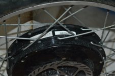
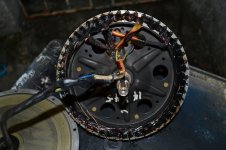
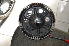
I have finally cooked my motor.

It was kind of high speed motor, capable of 94kmh max at full charge and ~86kmh on lower end, 24s LiPo 80Ah max 18Fet Lyens Infineon, being mounted in 22” outer diameter motorcycle rim/tire, on MB 50lbs + 200lbs rider.
It took a lot of abuse like large climbs at max load and fast riding at max throttle. Last words was written by ~5 min ride on full throttle and few climbs on the way. Then forced traffic light stop side by side on police station. :lol: On green it was over for motor and controller.

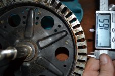
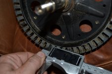
Anyway I will rewind it now. Any ideas and tips are welcome.

I purchased it with X5303 in mind, but after opening discovered it is Hx series.
 

Attachments

  • Picture 001.jpg
    Picture 001.jpg
    334.4 KB · Views: 1,987
  • Picture 011.jpg
    Picture 011.jpg
    147.9 KB · Views: 547
  • Picture 005.jpg
    Picture 005.jpg
    93.7 KB · Views: 547
  • Picture 002.jpg
    Picture 002.jpg
    160.6 KB · Views: 547
  • Picture 046.jpg
    Picture 046.jpg
    123.8 KB · Views: 547
It is also (Y) wound.

It is marked as 14x4
14 strands
4 turns.
It means actually 3 turns and half shared turn from every neighbor wind if available. Only last in and out toots have 4 winds.
Strands are 0.53mm cooper and 0.55 isolated.
~160gr of magnet wire on every phase
~6m long wire on every phase
2 peaces of bamboo stick in every slot. They will be hard to get! :D
 
Geez you worked that motor over. When I saw your first photo I was going to suggest that maybe it was just the phase wires shorting, but then I saw the next few shots - those are some of the blackest windings I have seen, you roasted that bad boy, at least you did the job properly....
 
You will have to think through how you are going to insulate the stator. Options would be Epoxy powder dip (like ScotchCast 260) and winding paper, so called "fish paper" (Nomex 410 Calendered Paper). I would be interested in what others come up with.

I think there was a plastic insulator over each face of the stator that likely melted into a soup with your degree of burn up.
 
Philistine said:
Geez you worked that motor over. When I saw your first photo I was going to suggest that maybe it was just the phase wires shorting, but then I saw the next few shots - those are some of the blackest windings I have seen, you roasted that bad boy, at least you did the job properly....
I wish it were just phase short, I almost burned my fingers by touching it as it stopped. Surprisingly halls are working fine, maybe because of absence of good thermal contact with stator, they just fell of as I cut ties holding cables.
bigmoose said:
You will have to think through how you are going to insulate the stator. Options would be Epoxy powder dip (like ScotchCast 260) and winding paper, so called "fish paper" (Nomex 410 Calendered Paper). I would be interested in what others come up with.

I think there was a plastic insulator over each face of the stator that likely melted into a soup with your degree of burn up.
If there was any insulation, it turned to ashes, I could not see anything but wire and kind of epoxi? it was soaked in.
Thanks for the recommendation, I was just braining about with no success. I will also round the edges with dremel to make the job of insulator easier.

Slot size 12.3mm by 4.7-5.7mm

Have done some math and want to go 17AWG 4strings 5 turns. Fill area= 20.74mm2 compared to 12.72mm2 of previous wind. 80% of previous KV.
It is maybe possible to go 16AWG 4strings 4 turns, but it is maybe more then I can swallow.

I am also thinking of individually winding each tooth and solder afterwards. Is it bad idea?
Here is how Karma did it.
http://www.youtube.com/watch?v=q_3DWhAq_X8&NR=1
 

Attachments

  • Picture 067.jpg
    Picture 067.jpg
    196.5 KB · Views: 547
  • Picture 068.jpg
    Picture 068.jpg
    150.1 KB · Views: 547
I look forward to following along as you do this project. Please keep us updated as I am sure others will
find the info valuable in the future.

That was one burnt motor for sure.
 
I for one am very impressed :lol:
Time to turn it into a liveforphysics-esque dickmotor.
 
I will also round the edges with dremel to make the job of insulator easier.
Just be careful with this operation, and use much prudence. The stator laminations are insulated with either an oxide or a very thin polymer one to another. They may be joined at a low flux area for mechanical stability (rigidity). If you grind more than one lamination together you can short the two together in a high magnetic flux area. This would have the effect of looking like a single, thicker lamination, with subsequently higher self heating (eddy current) losses at higher speeds.
 
ohzee said:
I look forward to following along as you do this project. Please keep us updated as I am sure others will
find the info valuable in the future.

That was one burnt motor for sure.

Yes I have over 100 pictures but they are to boring. I will do this as kind of guide, but do not really know what is useful and what is garbage. I am on the bike again, this time MXUS 500W DD fast wind motor on 24s 40Ah limited. :D

nicobie said:
Wow!

I've heard of an H series 48, but never a 53. the HS40 (10x6) is a big enough amp hog, no wonder you toasted your 53 running 100v/80a. :twisted:

Mine is a 25 (9x7) on 90v and is fast enough for me at 40 mph and I really have to work to get the temp probe to read higher than 70c.

Jeah, this thing was very hard on the controller, 18 fet eb218, it got hot even by 40kmh ride and inefficient as well. Up to 150% energy use side by side compared to GM based bike by same power and speed settings. It also ran up to 65 kmh on 99% speed limit 12S LiPo.
neptronix said:
I for one am very impressed :lol:
Time to turn it into a liveforphysics-esque dickmotor.
I have planed to do everything doable to make it fun to run. Maybe bearing mode and water cooling ( the easier one way kind
bigmoose said:
I will also round the edges with dremel to make the job of insulator easier.
Just be careful with this operation, and use much prudence. The stator laminations are insulated with either an oxide or a very thin polymer one to another. They may be joined at a low flux area for mechanical stability (rigidity). If you grind more than one lamination together you can short the two together in a high magnetic flux area. This would have the effect of looking like a single, thicker lamination, with subsequently higher self heating (eddy current) losses at higher speeds.
)
I only want to take sharp edges away, just little touch.
Question.
Will masking tape do same work as fish paper, several layers of course?

concer said:
Hey, you okay, I like new friends, I wish you a happy day
It is night here. :D Welcome to ES.
 
On green it was over for motor and controller.

I observed this strange phoenomenum many times when my controller blow..

It was often right after i have stoped the ebike at an intersection... and than when i restart on the green light... the motor just turn like 1/10 turn and stop... controlelr dead... :?

it was also embarasing vew times uen car drivers was looking at me unable to restart rising after the green light :lol: :oops: .. I was WTF is going on again!....

Doc
 
Interesting. FETs are hot. Block time shuts down current limits. Zero back EMF. Phase amps really high due to low back EMF and current multiplication. Heat in FET is phase amps squared times FET resistance which is high due to HOT FETs.

I wonder if there are other factors. VHF instability? Stories like this are usually quite similar. No launch, no acceleration, just FAIL. Major FET destruction. Seems like more than just would be explained by the hot FET effects.
 
In my case everything were simpler, just shorted phases in motor, all 3 somehow. I could not even push the bicycle without lifting rear wheel. :D Came home on motorcycle back holding bike in my hands. After checking with e bike tester, motor and controller RIP, surprisingly hall sensors still working (marked 41F).

Bad news for me, there is no needed cooper wire nor fish-paper in local specialized shop, need to go to next bigger city to get it.
 
That is an old tread here! :D
Found my stator in pile of junk 3 weeks ago. Got wire 1.55mm insulated (next size will not fit it some the openings between slots they vary go 1.65-1.95mm), fish paper and here we go!
file.php

file.php

So, it is 1 strand 6 turns. I probably could fit 7 turns, but 1-it would get extreme because of thick fish paper and last wind in the slot, 2.- my kv is already low with 6 turns, but I will compensate it with 24fet 150V Lyen controller. :D
To fill area: I did little mistake calculating it first time, it actually was 21.609637mm2 if we take .55mm d insulated and .53mm d bare, now I have only 22.051278mm2 taking 1.55mm d insulated and 1.53mm d bare cooper :oops: :cry: , yeah, I was lazy, should have done that last turn.

1 hall sensor was going crazy, so I replaced it (unfortunately have no 3 sensors to replace them all) :roll:.
 

Attachments

  • DSC_0270.resized.JPG
    DSC_0270.resized.JPG
    137.1 KB · Views: 1,467
The most turns clyte has been able to get on the 35mm stator with the wire size they use is 63

9 x 7 = 63 (3525) 7 strands, 9 turns
10 x 6 =60 (3540)
12 x 5 = 60 (3548)
14 x 4.5 = 63 (your motor before rewinding 3553?)

This is what they call them at 48v.

In your pic the 4.5 is clear and it looks like the other number might be 14.
 
nicobie said:
The most turns clyte has been able to get on the 35mm stator with the wire size they use is 63

9 x 7 = 63 (3525) 7 strands, 9 turns
10 x 6 =60 (3540)
12 x 5 = 60 (3548)
14 x 4.5 = 63 (your motor before rewinding 3553?)

This is what they call them at 48v.

In your pic the 4.5 is clear and it looks like the other number might be 14.

It actually is 32mm stator. It is marked as 14x4.5 but it actually got 3.5 turns and 4 turns in some places. It was kind of high speed wind doing 94 kmh on fully charged 24s in 22" outer D wheel and far over 100kmh in 26". :D

Few more pictures.
DSC_0277.resized.JPG
Hall and temp sensor wires, unfortunately have no temp sensor now :roll:
DSC_0280.resized.JPG
I just took original phase wires.
But wait, there are 6 of them. :lol:
 
Back
Top