Diodes for series-parallel Batteries

llile

1 kW
Joined
Dec 18, 2010
Messages
457
Re: Diodes and charging question…

Postby dnmun » Thu Jan 12, 2012 5:13 pm
you do not need diodes to connect them in parallel. period. just be certain they are charged to the same voltage before connecting them in parallel. i think i already covered it, not sure why it is so hard to understand.

you do not need diodes

you do not need diodes

you do not need diodes

diodes make heat and rob power, they will catch your pack on fire if they are in the bag with the pack.

you do not need diodes.

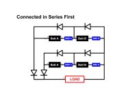
Well, I respectfully disagree. Li Ping recommends the attached circuits for series and parallel batteries. Let's pick them apart and try to understand them, shall we?


What does that diode in parallel with the battery do? Apparently it is always reverse biased, and no current would flow, right? Nope, it does have a function.

Take a look at this Wikipedia article http://en.wikipedia.org/wiki/Flyback_diode for a little background on flyback diodes, then think through the following:

Your motor is a large inductor. Inductors will resist changes in current flow. If you suddenly cut off voltage to an inductor, current will continue to flow in the same direction, generating a large negative voltage spike, in the opposite polarity to the original voltage. Suddenly, there is a big negative voltage across your battery, and the sensitive electronics of your BMS. Kapow! But the reverse biased diode in parallel with your battery suddenly becomes forward biased, and returns this current safely to the inductor. This protects the BMS. I don't know it the battery itself would be damaged by the spike, but electronics certainly would.

These spikes can be extremely high voltages. In electronics class, we used to zap unsuspecting N00bs by having them measure the resistance of a large inductor, while holding the bare leads with their fingers. The 1.5 volt battery in the ohmmeter (this was in the old school when ohmmeters had DIALS as God intended) would charge the inductor, and inevitably the current would eventually be broken, generating a large flyback voltage, which then zapped the unsuspecting greenhorn holding the leads, generating mirth all around, except for him.

It is common to see flyback diodes on motors, relays, and coils. I've seen microcontrollers fried because a relay in the same circuit had no flyback diode. The flyback diode is a great idea to protect the BMS.


How about the series diode? Well, you can argue that it does waste some power, and I'd agree. A diode that carries current normally does generate heat, and you have to account for that if you use it. If you put it inside a bag, and haven't accounted for the heat, you may cause some trouble. Properly heat sinked it should be OK.

The series diode is protecting one battery from discharging into the other, and ensuring that, if one battery is stronger than the other for any reason, current goes into the motor rather than the other battery. I don't know if a LIFEPO will be damaged by reverse current flow, or just charged. I also don't know what this does to the sensitive BMS.

If these two battery packs are perfectly balanced, and charged to exactly the same voltage, then the diodes would not accomplish much. But what if they are not? One weak cell, variations in cell voltage? If one pack is weaker than the other, esp as they age, then the stronger pack will likely take most of the current. Will your battery packs really deliver the rated energy, if one pack is taking all the load? The diodes in this case help balance the two packs. This is also a commonly used circuit in various contexts from RV batteries to electronics.

How will one know if the batteries have been charged to the same voltage? I suppose one could add voltmeters, but most people just plug in the battery chargers at the end of a ride and leave it. What if the BMS are not balanced? What if one forgets to plug in one of the batteries? There are enough variables that I'd argue the series diodes add a level of safety, of course with some attendant complications.

How much heat? How much power? Let's say you are using a 72 volt battery pack and a nominal 1000 watt motor. That could be a pretty fast ride. You'll be pulling on the order of 14, lets say 15 amps to make the math easy. Each diode handles half this current. The datasheet for a Vishay 100BGQ100 Schottky diode says it would be dropping about 0.6 volts at that current. 0.6*7.5 = 4.5 watts for each diode or 9 watts for the pair. That's certainly going to need to be clamped onto a piece of metal. Isolated inside a bag that diode is certainly going to get too hot. But how much is 9 watts? It drops the efficiency of your 1000 watt motor by a little less than 1%. Maybe your flash flag uses up a similar amount of power. Lose the knobby tires, and you've probably made up for it.

If Li Ping recopmmends the series diode, I am liable to believe him. I'd like to hear From people who have run without the series diodes, how did things fare as the battery packs age? Has anyone done any measurements on battery capacity? I know there are strong advocates of not using series diodes in a parallel battery, however I believe that, properly designed, they probably do add some value.
 

Attachments

  • Series Parallel.jpg
    Series Parallel.jpg
    45.2 KB · Views: 6,988
  • series first.jpg
    series first.jpg
    69.6 KB · Views: 6,527
I like the diodes too, as it guarantees that I can never screw up by hooking up packs that accidentally are at very different voltages, which is not likely to happen but could happen for whatever reason (mostly human error). I like the determinism of that. I've got two plug and forget Headway packs running in parallel through ideal diodes from "Tiberius on ES"...and I've basically never had to think very much or worry about them, after I got them re-jiggered from 2x8 cell layout to 6/6/4 layout and got the BMSes installed. I don't care about the marginal losses of the diodes - I'm not smart enough to figure out all the things that could go wrong.
 
Well thought out and articulated post. Thank you.
 
Kent said:
Well thought out and articulated post. Thank you.

You are welcome! I was just talking to a PHD I know, and he was saying that other things happen to batteries as they age. Batteries at different *temperatures*, if I understood him correctly, will have different voltages, enough to reduce the capacity of a pack, causing mismatch between parallel packs. THis can happen in electric cars when some batteries are close to the cab, and others out in the breeze, he was telling me. He also asserted that as batteries age, the cell voltages will begin to vary significantly, esp. if one cell is much weaker than others. ALl this says that the series diodes do accomplish something as batteries age, as they get slammed around in normal use, and as they suffer normal wear and tear.

Of course, at lower voltages, like 36V, a series diode has a bigger effect. For the same power, one is pulling twice the current at a lower overall voltage. But likely a 36V system won't have more than a 500 watt motor. At least I wouldn't design it that way.

YMMV. Heat sinks are critical when puling anything over a watt. They aren't very hard to design, if you've done one before. WIhtout a heat sink, 5-10 watts can get hot fast. Don't ask me how I know this. :mrgreen:
 
wow neat. you know someone with a phd. what does anything in this thread have to do with anything except you decided you wanted to put diodes inline?

big deal. i asked the other guy to do it and report back on how hot. maybe if you do that it will be worth reading.

you do not need diodes in series or in parallel with identical lifepo4 packs.

nobody reading this should think it means anything more, and newbies should not be misinformed just because you don't know any electronics to understand it.
 
dnmun said:
wow neat. you know someone with a phd. what does anything in this thread have to do with anything except you decided you wanted to put diodes inline?

big deal. i asked the other guy to do it and report back on how hot. maybe if you do that it will be worth reading.

you do not need diodes in series or in parallel with identical lifepo4 packs.

nobody reading this should think it means anything more, and newbies should not be misinformed just because you don't know any electronics to understand it.

Hi dnmun,

i'm a newbie on this topic i must say.

You say diodes are not needed.

I think it would be interesting to read the longer post of llile (» Sat Jan 14, 2012 5:08 pm) above and respond to the arguments is bringing in favor of using diodes.

I do not know any of you, so i cannot say who knows more on the topic. So what's left for me is the arguments, and eventual counter-arguments people are bringing.

I think it's a fair way to progress on this topic.

thanks for your help.
 
llile said:
Your motor is a large inductor. Inductors will resist changes in current flow. If you suddenly cut off voltage to an inductor, current will continue to flow in the same direction, generating a large negative voltage spike, in the opposite polarity to the original voltage. Suddenly, there is a big negative voltage across your battery, and the sensitive electronics of your BMS. Kapow! But the reverse biased diode in parallel with your battery suddenly becomes forward biased, and returns this current safely to the inductor. This protects the BMS. I don't know it the battery itself would be damaged by the spike, but electronics certainly would.

I don't believe the red bit. How you're going to get a negative voltage accross a 48V battery with only a few milli-Ohm internal resistance ?

Probably there's something going on with the BMS that prevents regen... ?
 
DMun can you explain by what you mean by "identical packs". I have two 48V 15Ahr Headways. One is at 50% SOC and one is at 100% because for what ever reason pack A didn't get fully charged (and I wasn't aware of it). To me, that seems risky. They don't seem "identical" at that point. And my ideal diode is never more than warm. I don't think you are accounting for the possibility of human error. And I often want to hook up another pack which is only 10Ahr to a 15Ahr one of them. Same story. I don't consider them identical. For reasons of determinism, and flexibility, such as hooking up a Headway and a Ping (which I often do), I like diodes. Because I don't have to think. Ping must have a reason. ARe you sure you have accounted for all the ways that a human could mess up? Why not have some cheap failsafe insurance? And people often want to run non-identical packs...I do all the time, both in terms of battery size and cell type, and different bms-es.
 
llile said:
Your motor is a large inductor. Inductors will resist changes in current flow. If you suddenly cut off voltage to an inductor, current will continue to flow in the same direction, generating a large negative voltage spike, in the opposite polarity to the original voltage. Suddenly, there is a big negative voltage across your battery, and the sensitive electronics of your BMS. Kapow! But the reverse biased diode in parallel with your battery suddenly becomes forward biased, and returns this current safely to the inductor. This protects the BMS. I don't know it the battery itself would be damaged by the spike, but electronics certainly would.
The MosFETs in your controller have a parasitic diode which is enhanced to aid switching characteristics and help suppressing the flyback effects.

People are nos as dumb as you think :roll:
 
Re: Diodes for series-parallel Batteries

Unread postby dnmun » Tue Jan 17, 2012 12:17 am
wow neat. you know someone with a phd. what does anything in this thread have to do with anything except you decided you wanted to put diodes inline?

big deal. i asked the other guy to do it and report back on how hot. maybe if you do that it will be worth reading.


I will ignore the ad hominem argument for a while

you do not need diodes in series or in parallel with identical lifepo4 packs.

nobody reading this should think it means anything more, and newbies should not be misinformed

Got any math and physics behind that statement, or shall we just trust that your assertions are true? Let's see the math!

just because you don't know any electronics to understand it.

Ignoring yet another ad hominem argument.

Please post some logical, rational, and physics-based reasoning behind these interesting assertions. I'd love to hear if you've done tests, or measurements, on diodes vs. no diodes. You've posted this assertion several times, perhaps you've also posted the reasoning behind it, however I have not run across these posts. Please enlighten us! Perhaps you can explain this assertion that diodes are not needed, rather then just repeating it, and explain logically why battery experts such as Li Ping, and my PHD friend, all say the opposite.
 
Lebowski said:
llile said:
Your motor is a large inductor. Inductors will resist changes in current flow. If you suddenly cut off voltage to an inductor, current will continue to flow in the same direction, generating a large negative voltage spike, in the opposite polarity to the original voltage. Suddenly, there is a big negative voltage across your battery, and the sensitive electronics of your BMS. Kapow! But the reverse biased diode in parallel with your battery suddenly becomes forward biased, and returns this current safely to the inductor. This protects the BMS. I don't know it the battery itself would be damaged by the spike, but electronics certainly would.

I don't believe the red bit. How you're going to get a negative voltage accross a 48V battery with only a few milli-Ohm internal resistance ?

Probably there's something going on with the BMS that prevents regen... ?

Well, current through an inductor will tend not to change even if the voltage is removed. It tends to remain constant for a brief time. This current will die out quickly, dissipating as heat in whatever resistance is at hand, but for a brief time, on the order of milliseconds. But it is enough time to fry some electronics, which is why we had to install flyback diodes on a relay circuit we were building into some commercial electronics. Perhaps the electronics used in bikes already have some protection for this problem? Howebver, flyback or parallel diodes are recommended by battery experts like the estimable Mr. Ping.

Meanwhile, if you'd like to test this out, you can do the same experiment that we'd do on the N00bs in the electronics lab - Find a really large inductor, hold the leads with your bare fingers, and touch them to a 9V battery. You'll be a *believer* in about 100 milliseconds after the battery voltage is removed!
 
migueralliart said:
Do I need diodes for two packs connected in parallel :
1 36V Li-ion 14Ah pack
1 36V Li-PO 3Ah Pack (2-5s packs)
?
Well, the answer is what we're discussing on this thread. I'd say those packs are not well matched, being different chemistry and power. If you do parallel them, series diodes will definitely be needed IMHO to prevent one pack from discharging into the other, as they will be at different voltages as the cells discharge at different rates, and also since there will be different currents through the series resistance of the pack. Others have indicated they have used mismatched parallel packs successfully with diodes, but I have no direct experience with this, only theory.
 
llile said:
Lebowski said:
llile said:
Your motor is a large inductor. Inductors will resist changes in current flow. If you suddenly cut off voltage to an inductor, current will continue to flow in the same direction, generating a large negative voltage spike, in the opposite polarity to the original voltage. Suddenly, there is a big negative voltage across your battery, and the sensitive electronics of your BMS. Kapow! But the reverse biased diode in parallel with your battery suddenly becomes forward biased, and returns this current safely to the inductor. This protects the BMS. I don't know it the battery itself would be damaged by the spike, but electronics certainly would.

I don't believe the red bit. How you're going to get a negative voltage accross a 48V battery with only a few milli-Ohm internal resistance ?

Probably there's something going on with the BMS that prevents regen... ?

Well, current through an inductor will tend not to change even if the voltage is removed. It tends to remain constant for a brief time. This current will die out quickly, dissipating as heat in whatever resistance is at hand, but for a brief time, on the order of milliseconds. But it is enough time to fry some electronics, which is why we had to install flyback diodes on a relay circuit we were building into some commercial electronics. Perhaps the electronics used in bikes already have some protection for this problem? Howebver, flyback or parallel diodes are recommended by battery experts like the estimable Mr. Ping.

I know but this still doesn't explain the bit in red.
 
Lebowski said:
OK, let's say the "red bit" was worded rather imprecisely. We'll try to be a little more precise. Imagine a simple circuit, with a battery, a switch, and an inductor. Turn on the switch, and current will begin to flow. Current flows from the positive end of the battery, through the circuit, to the negative end. The current enters the inductor at the positive battery voltage, lets call that point A, leaves through the other end we'll call point B which is at the negative battery voltage. There is a small but real amount of resistance in the wires, coil, etc.

Now interrupt the switch. The current in the inductor won't change in the first few milliseconds, dieing at an exponential rate,( and back in college I could have actually quoted the math at you, I'd look it up again however Wikipedia is dark right now and the exact calc doesn't matter) governed by the resistance encountered in the circuit and the inductance.

However, the voltage on the inductor has done something interesting. You know how the positive end of the battery was supplying current earlier? The inductance is now supplying current through its collapsing magnetic field. Current is flowing from point A to point B, and point B becomes more positive than point A, just like the positive terminal of the battery would. If the inductor were a battery, it's positive terminal would be at point B, 'cuz that is the end suppyling the current. The voltage on the inductor has flipped, going negative. All hell can break loose at this point if sensitive electronics are involved, or an unsuspecting N00B is holding onto the terminals barehanded. :twisted: This so=called flyback voltage can be a brief but intense spike, thousands of volts under the right conditions. After you call your congressman and complain about SOPA, look it up on Wikipedia tomorrow when it is back online. As this current has no place to go, and the inductor looks sort of like a current source for a brief instant, voltages in the circuit can rise to extreme levels. However, if there is a path around the inductor, via a diode, then the current pulse is safely shorted out, and soon dissipates.

If that doesn't do it for ya, I'll have to start drawing diagrams, and I don't have the patience right now. My tooth hurts like hell, which is the only reason I am up at 1:30 AM anyway. I hope this darn dentist is open tomorrow morning, I am going to camp out on his doorstep like an Occupy protester!

PS. Call your congressman and complain about SOPA. It pains me more than this tooth!
 
But how would the voltage get so high... it would just charge the battery a bit. The battery can support current in either direction just fine.
I am still trying to understand the need for diodes for parallel batteries... so what if one battery charges the other.... this is an expected result if you have a high power batt and low power batt in parallel. most of the current will come from the high power pack under high load. remove the load and the high power pack will be at lower resting voltage because it was discharged more. Thus the lower power battery will charge up the high power battery when the system is at rest.
I think this is okay, and, if you prevent it, then more and more current will have to come from the low power battery to the load, potentially getting into a situation where you would defeat the purpose of paralleling a hp and lp batt...
I am talking about an electric car scenario where power is used in bursts.
 
I've never heard of anybody fitting flyback diodes on their bike. The effect would be the same whether you had one or two batteries, so if they were needed, everyone would need one.

I've run two entirely different batteries in parallel for extra capacity. I didn't use diodes and everything worked perfectly. It ran like that for more than a year in regular use until we sold the bike like it. The important thing is that the batteries are at the same voltage when you conect them and that you disconnect them from each other when you charge them otherwise the one will charge the other through the discharge leads, which bypasses the charge protection in the other one's BMS unless it uses the same MOSFETS to switch off both charge and discharge like some BMSs have. Ididn't worry about that on my paralel batteries. I just left them connected all the time and only charged the one.
 
okashira said:
But how would the voltage get so high... it would just charge the battery a bit. The battery can support current in either direction just fine.
I am still trying to understand the need for diodes for parallel batteries... so what if one battery charges the other.... this is an expected result if you have a high power batt and low power batt in parallel. most of the current will come from the high power pack under high load. remove the load and the high power pack will be at lower resting voltage because it was discharged more. Thus the lower power battery will charge up the high power battery when the system is at rest.
I think this is okay, and, if you prevent it, then more and more current will have to come from the low power battery to the load, potentially getting into a situation where you would defeat the purpose of paralleling a hp and lp batt...
I am talking about an electric car scenario where power is used in bursts.

If the batteries are joined in parallel, their voltages will always be the same, so you can't have one charging the other. They only discharge, going down in voltage equally, with the largest capacity one providing most of the current, though less current than it would on its own.
 
d8veh said:
okashira said:
But how would the voltage get so high... it would just charge the battery a bit. The battery can support current in either direction just fine.
I am still trying to understand the need for diodes for parallel batteries... so what if one battery charges the other.... this is an expected result if you have a high power batt and low power batt in parallel. most of the current will come from the high power pack under high load. remove the load and the high power pack will be at lower resting voltage because it was discharged more. Thus the lower power battery will charge up the high power battery when the system is at rest.
I think this is okay, and, if you prevent it, then more and more current will have to come from the low power battery to the load, potentially getting into a situation where you would defeat the purpose of paralleling a hp and lp batt...
I am talking about an electric car scenario where power is used in bursts.

If the batteries are joined in parallel, their voltages will always be the same, so you can't have one charging the other. They only discharge, going down in voltage equally, with the largest capacity one providing most of the current, though less current than it would on its own.

Not true at all. Let me explain.

Place a high power Samsung 25R 18650 in parallel with an older cheap chinese or older lg/panasonic 2500 mah-hr cell rated for only 1 amp.

If the cells are separate, and charged to 4.000 volts, draw 3 amps from each cell for one second:
The Samsung 25R will sag to ~3.95V under load. (50mV)
The older cheap cell with sag to ~3.75V under load. (250mV)

Remove the load from both, and they will both be at ~3.998V resting, because you drained the same number of columbs from each. (3A for 1 sec)

However, now, place them in parallel with 4.000V each. Let's say they are welded with thick copper/nickel so the resistance between them is <0.001 ohm.
Now we know they have to remain at the same voltage at all times. We agree on that.

Now draw 3A from this parallel set. Or 6A. What will the voltage sag to?
3A: 4.000 > x > 3.950V [if the 25R will only sag to 3.95 ALONE under 3A, it wouldn't perform WORSE with another cell in parallel.]
6A: ????

As a thought experiment, to try and figure out the sag at 6A, let's say these cells have a constant impedance. The 25R sags 50mV per 3A. Thus, it would sag 100mV at 6A.
Thus, the 25R alone would sag to ~3.90V with a 6A load.
With the other cheap cell wired in parallel, we can only expect the sag to be less:
3.950 > X > 3.900 (The real answer is about ~3.910V. You could calculate it.)

So the voltage will be somewhere higher then 3.900. Let's say 3.910V.
We also know the cheap 2500mah cell sags to 3.75V under 3A.
But if we've only dropped the voltage to 3.901 volts, we know the cheap cell is going to produce much less then 3A. In fact, it would be (4.00-3.91)/(4.00-3.75)*3A = 1.08A (assuming constant impedance)
Thus, the 25R must come up with the extra 6.00-1.08 = 4.92A.

Keep this load on the parallel set from some set time, say 10 seconds, and the 25R will have output 49.2 amp-seconds, while the cheap cell only 10.8 amp-seconds.
Thus, clearly, we have drained the 25R more then the cheap cell. If you were to disconnect the load and then immediately disconnect their parallel connection and allow both to reach resting voltage you would find that the 25R has a lower resting voltage because it had to output more amp-hours.

If you hadn't disconnected the parallel connection (or never disconnected them) and had an ammeter between the parallel connections, you would find that the cheap cell would be actively charging the 25R cell upon disconnect, and, if you were to measure this current over time, it would have an exponential decay and if you were to sum it over a long period of time, you would discover that the amount of charge transferred would be exactly equal to (49.2 - 10.8)/2 = 19.2 amp-seconds.


Thus, a high power cell (low impedance, R1) in parallel with a low power cell (high impedance, R2), assuming similar chemistry and short term power bursts will result in the following behavior:
-Under load, the high power cell will output most of the current, A, draining it more quickly. The Amount of current coming from each cell is actually a function of their impedance relative to both cell's equivalent parallel impedance. The equations simplify to:
(A = A1+A2)
A1/A2 = R2/R1
-Upon removal (or reduction of) load, The high power cell would have a lower disconnected resting voltage (because it was drained more)
-The low power cell would charge the high power cell until their disconnected resting voltages became equal (or the discrepancy in charge was transferred)

For longer-timed loads, it gets a bit more complicated. The amp distribution will start off at A1/A2 = R2/R1, but will slowly shift to the lower power cell supplying more amps as the high power cell becomes more drained.
The problem here is if you have a 2.5V cut off, it's quite possible you may end up in a situation where theoretically once cell becomes over-discharged based on the cut off voltage and the per-cell amps.
Thus you'd want a safety factor here, say use a 2.8 or 3.0V cut off.

charging should generally be ok because you know it should be fine to supply 4.2V to both, you may have to lower charge current to make sure one cell doesn't take too many amps.
 
Kiriakos GR said:
What makes me mad is when some one trying to present an argument as correct, and he does that by using plain words and a lot of imagination.

Where is a screenshot of the spike in a screen of one Oscilloscope?
Why no one measured the voltage spike electrical parameters?
Does it look as regular fart with significant noise? Is it a tiny fart? That no one cares about?

In the navy they are using all sort of battery connection types, powering strong motors and not toy motors of few hundred of Watts.
They should have used any improving battery connection techniques all ready.
Did they?

While I do favor inquiring minds because I am one too, the all topic is based at no measurable facts at all. :|

The theoretical explanation of @okashira is nothing more than regular resistance Ohm law.
Which it is not far from the truth, but the question is: Does all this theory give a usable fact which has some practical value? :)


Why no one analyzed yet and report the benefits of a motor controller?

And now the more significant question than all ….. Is this topic related about people playing with electric motors by not using any recently made motor controller?

In conclusion, if some even thinking that a formation of diodes can replace the benefits coming from the more complex electronics of today? He is a dreamer with out any sort of technical background.
And personally I do avoid hanging around with those guys.
Those are the same people looking for a 60A power switch so to activate one motor over a bicycle with no help from other electronics, which is stupid.
Only a car starter works that way and it does that for 4-5 seconds its time.

I will leave each to their own to make this decision.... :)
 
I am "upping" this interesting subject because I am going to put 2 36V lifepo4 batteries in série and am questioning about charging them as a pack of 72V.

In all the written things here, nobody did take into account that this is the controller that will have to manage the flyback effect, and will have to implement flyback diode into the output circuitry? I am sure that mass opposite voltage could kill the controller mosfet. It should be ok for the battery as as soon as throttle goes to 0, PWM stops and mosfet stop to pump amps from the battery...
 
greg_p said:
I am "upping" this interesting subject because I am going to put 2 36V lifepo4 batteries in série and am questioning about charging them as a pack of 72V.

In all the written things here, nobody did take into account that this is the controller that will have to manage the flyback effect, and will have to implement flyback diode into the output circuitry? I am sure that mass opposite voltage could kill the controller mosfet. It should be ok for the battery as as soon as throttle goes to 0, PWM stops and mosfet stop to pump amps from the battery...

This a really bad thread and full of bogus info.

Your question/comment is more relevant here:
https://endless-sphere.com/forums/viewtopic.php?f=30&t=31804
 
Back
Top