Cutouts: Solved! Sine Wave Controller S12S

docnjoj

1 GW
Joined
Sep 29, 2007
Messages
5,787
Location
Fairhope AL
Well it worked with the wheel elevated except for a few hiccups at higher speeds. On the road it worked for a few minutes but very low power, then I figured out cruise control and it worked slow but OK for another few minutes. Then it kept putting on it's brakes and then going again (no brake sensor is fitted yet) and then it failed completely.
Possible failure points:
1. Wrong phase/halls
2. ?
I will continue to test it on the stand with the wheel elevated and then test it with the meter removed and appropriate wires connected.
Not exactly auspicious or plug-n-play.
Suggestions welcome from folks that have S12S or other similar controllers or just know a lot more than I do (not too hard to do) :D
otherDoc
 
I don't have an s12s or even know what it is, but I have a suggestion anyway. Since every hall combo has one good phase combo, and every phase combo has one good hall combo, with a new controller or motor always check all 6 combinations of whichever is easier to swap (halls or phases) leaving the other static. You'll get one good smooth low current at no load result in that 6, though it could be reverse. If you don't, then something else is wrong. If the good one is reverse, swap any 2 (only 2) of the wires you were keeping static and go back and find the right combo again for forward of the remaining 5.

I never even consider a test ride until I'm certain, which requires nice smooth sound especially on the startup and low current at WOT with the wheel off the ground. To ensure I don't blow anything I use a fairly thin gauge wire with alligator clips to complete my battery connection, which acts like a fuse and it can't pass enough power to blow anything. Plus it gives me an easy means to connect the multimeter in line once I think I have the right wiring and measure the no-load current to verify.

John
 
Thanks John, but "it's dead Jim". No response to anything including a new throttle. It does give error messages even with just a signal ground exchange and, of course if halls or phases are disconnected. The screen looks fine and works fine, but no power to the wheel. It seemed to be smooth and only about 1 amp power draw even at higher RPM. Well, it was only 30 bucks or so and was an experiment to see about possible Pedelec riding but the motor does cog now with the phases connected and spins free, with them removed, so maybe FETS? Luckily I have a bunch of other controllers including my old faithful Infineon that I didn't even take off from the bike. I guess Sine Wave will have to wait until others test it out.

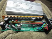
I'll open it up tomorrow and take pictures so we can see the technology involved, (if any).
Thanks
otherDoc
 
John in CR said:
I don't have an s12s or even know what it is, but I have a suggestion anyway. Since every hall combo has one good phase combo, and every phase combo has one good hall combo, with a new controller or motor always check all 6 combinations of whichever is easier to swap (halls or phases) leaving the other static. You'll get one good smooth low current at no load result in that 6, though it could be reverse. If you don't, then something else is wrong. If the good one is reverse, swap any 2 (only 2) of the wires you were keeping static and go back and find the right combo again for forward of the remaining 5.

I have since found this not quite true as it depends on how the motor is timed and the winding scheme.. I have had hub motors that requires a hall sensor wire to be swapped for it to work and none of the 6 phase combos would run either way ( smoothly ) but its a very good starting point and 9 times out of 10 this is all you need to do.
 
What brand? Geared or DD? I've only heard of a BMC geared hubbie that was an issue years ago. Geared I can see the potential for odd timing since they are directional, but for a motor that can run either way the logic puzzle doesn't work. It runs in a circle so which hall is the starting point would be irrelevant as long as it can run either way. If I'm missing something, then I want to understand.
 
It would run but very badly , i have had it on a DD generic 1kw rear hub kit from China and on a the new :? :? :? gng 600w motor. It's down to the timing, a motor wound in WYE with fixed halls is timed for optimal performance in only one direction, well this is what I put it down to, I never bothered to work through the logic for a definite answer. I normaly just swap phase wires to find the correct combo but on these occations I needed to swap a sensor also then the motors worked as they should . I may work through the logic when I have a bit of spare time because now you have got me thinking maybe I just had a brain fart at that time :|
 
I don't know what happened to your sine controller, but I can tell you getting one working is worth it if you enjoy buttery smooth silent torque. :) They turn loud growling motors into eerily silent ones.
 
I have a S12S. I just plugged it in and it worked perfectly with a Bafang BPM.

You should never run a motor if it's intermittent or juddering because you can damage the mosfets in the controller, but just because yours isn't working now, it doesn't mean that it's damaged. What motor were you driving?
 
d8veh said:
I have a S12S. I just plugged it in and it worked perfectly with a Bafang BPM.

You should never run a motor if it's intermittent or juddering because you can damage the mosfets in the controller, but just because yours isn't working now, it doesn't mean that it's damaged. What motor were you driving?

A EBK 9C clone, 2807 or 9 x 7 which works fine on the regular square wave controller. I'm going to try some more combinations today and then open the case and take pictures. We shall see.
otherDoc
Oh Yes, the motor did run smooth at about 1 amp draw with the wheel up. It did have a strange response while being tested on the road, and finally quit altogether.
 
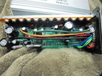
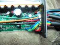
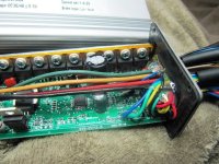
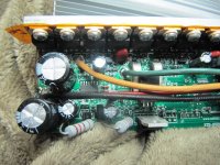
Here are Pictures. Non-working controller but no visible signs of damage.IMG_0656.JPGIMG_0658.JPGIMG_0660.JPGIMG_0657.JPGIMG_0659.JPG
 
I don't know if those pics will help anyone, but the board seems well made and there are a bunch of surface-mount parts. 63 volt caps and the FETs are 80nf75 I believe. So it should have had no trouble with 36 volts nominal that I used.

I believe I probably ran with mis-matched Halls/phases and that is what caused the destruction but It could have been faulty from the get-go. I think not. d8veh has one running. I have done a bunch of Hall-Phase matching with new controllers/motors and this is the first one that I blew.
I can see where Justin's self learning controllers are worth the extra money.
otherDoc
 
The instructions say automatic selection. I run at 36 nominal.
otherDoc
 
My new one just arrived and it has an additional grey loop of wire in addition to the blue/black loop that we classified as a cruise control. I hope it is a self learning loop. We will see soon.
otherDoc
 
Did you have to pay for the replacement?

I just re-read your first post. I also have the S06S controller integrated in my bottle battery. It had the same behaviour as yours. It was OK at low power and speed, but once it got going, it seemed to lose sync, which I though was because of the high-speed motor I was using. I need to try it on another motor to confirm.
 
d8veh said:
Did you have to pay for the replacement?

I just re-read your first post. I also have the S06S controller integrated in my bottle battery. It had the same behaviour as yours. It was OK at low power and speed, but once it got going, it seemed to lose sync, which I though was because of the high-speed motor I was using. I need to try it on another motor to confirm.
Could be defective. My S12S did similar to your controller. I got another and will test today or tomorrow. Yes I paid as shipping back was more than the controller cost. I buy cheaper items from China, but probably not batteries. Maybe Ping or Cellman.
otherDoc
 
I have an s12s on order. Can't think where i saw it, but a sticker says a wire loop effects lvc. I do remember the loop is not one colour though. It is two different coloured wires together.

I was actually hopeful it could be changed anyway. I thought bmsbattery listed how to do this through the lcd interface. Some math I didn't quite get the meaning of.


Nope... Not bmsbattery. Here it is

Note: How to determine the value of the parameter P5 ? The formula is LVC+P5/3.77.

For 24V battery, LVC=20V, P5/3.77=1.

For 36V battery, LVC=30V, P5/3.77=1.5.

For 48V battery, LVC=40V, P5/3.77=2.

You can adjust P5 parameter by your own battery discharge curve.

It is a smart LCD. You can not test it by only voltage. You need to install it on your E-Bike and pedal for 3-5 seconds. Then the LCD will show battery level normally.

What is that talking about... I was hopeful the lvc was programmable, but the question was never answered when I asked china.
Edit: It looks like I need to transpose? the formula in to a more meaningful order. I can feel my head dropping down towards the keyboard as I glaze over and start dribbling. I canny be arsed
 
Man, this LVC setting is confusing. Those obviously aren't formulas for P5. It looks like the setting represents a difference between the nominal battery voltage, and the approximate cutoff. Like this:

24V battery, P5=1: 24-(1*3.77)=20.23V LVC
36V battery, P5=1.5: 36-(1.5*3.77)=30.35V LVC
48V battery, P5=2: 48-(2*3.77)=40.46V LVC

So my question is how to adjust the LVC to other values, i.e. What is the actual formula for calculating the absolute LVC value?
 
I think it is just so the meter can read the proper battery voltage. It would be great if it were and adjustable battery voltage cut off but I doubt it.
otherDoc
 
friendly1uk said:
I have an s12s on order. Can't think where i saw it, but a sticker says a wire loop effects lvc. I do remember the loop is not one colour though. It is two different coloured wires together.

I was actually hopeful it could be changed anyway. I thought bmsbattery listed how to do this through the lcd interface. Some math I didn't quite get the meaning of.

The new one that I just got has 2 loops. One is the black/blue which I was told by BMS was Cruise Control Active. I am hoping that the other loop (all thin grey wire with black connectors) is self learning. Will test later or tomorrow with the bike in the air (of course) I already broke one of these S12S thinking Hall/Phase was OK. It could have been and the controller faulty but I don't think so.
These controllers are supposed to work without setting the LCD screen. It should come with auto run set up and then you can set the speed etc. We will see.
otherDoc
 
If it *does* have a working "adjustable" LVC, and it somehow gets set higher than your battery's voltage, wouldn't it cause the controller to appear to be dead like that?


I kinda wish I had time and equipment set up to troubleshoot controllers here at Bill's, cuz I am now curious as to why that controller would just die.


FWIW, if there are a lot of SMT parts, and some of them arent' fully soldered down, I guess vibration could crack the solder joints and if they're the right parts it could cause them to not work. (Even something as simple as a pull-up resistor on a hall, or brake signal, etc, probably). Some might be easy to check, some might require a schematic or doing a bit of reverse-engineering.

Same thing could happen to thru-hole parts too, but they're usualy a lot easier ot see such problmes with. (for me, at least)


FWIW, the OP symptom of "putting on it's brakes" intermittently, then failing, could be hall/phase combo *or* could be actually it putting on the brakes, meaning something inside either shorting or opening in the ebrake circuit, causing it to literally brake, and then when it's stopped it would be disabled from responding at all, once the brake stayed "on". Something as simple as a broken-inside-insulation wire, or a cracked solder joint, or broken trace or thru-hole, or a solder ball or whisker under or on something.
 
docnjoj said:
I think it is just so the meter can read the proper battery voltage. It would be great if it were and adjustable battery voltage cut off but I doubt it.
otherDoc

Yes, hearing someone else pose my question has helped me. It is more related to setting the expected upper voltage. Perhaps to account for chemistry. For me it means using the 40v lvc for my 44v 12s pack, giving 3.3v lvc per cell. I will need this p5 function to change what is considered charged. As my full 44v pack will look rather depleted on a 48v battery meter if I don't adjust anything. Quite pleasing actually, as my bms cuts at 3v per cell. The controller will power down just above bms lvc, leaving power for my lights to run after motor shutdown. But I digress.


Of the 3 larger caps, the one in the corner never looks quite right. The metal disc should feel flat if you rub it. I'm not convinced from here.
 
My understanding is that self-learning is fully automatic like the KU series, and so is voltage detection. There was one version of the KU123 that had a wire loop for changing the LVC. It brought an extra resistor into the divider to change the ratio. I can't understand that P5 setting at all, but I believe that it only affects the way the battery indicator in the LCD behaves; however, I was out on mine today, and my 20aH Ping seemed to cut out after about 6aH. this has got me thinking whether there is something different in this S12S setup. It's the first time that I've gone over 20 miles since I fitted it. I thought perhaps my battery was out of balance, but I don't know now. I'll have to check it with a voltmeter next time.
 
Well so much for BMSBattery. 2ndbrand new S12S controller did NOTHING! No wheel spin under any circumstances! This is the same setup that did 21 miles on Sunday with the old Infineon perking away. Any yes, it works fine with the old Infineon hooked up again. I did order an S09P also but will try that tomorrow. Out of energy today. I tried several different combos of phase and even changed one halls combo. NADA! Nuttin! no motion at all from motor. Not even a wiggle! At least the first S12S spun up a bit and ran the trike about a mile before it died. Connected grey loop and blue/black loop and disconnected them and tried each one separately. Power was removed with each hookup/unhook and then restored. Yuk!
otherDoc
 
Back
Top