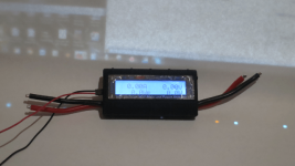
Watt Meters keep dying

Greggie-e

1 mW
Joined
Oct 17, 2013
Messages
16
Location
Perth Western Australia
Hey guys sorry if this has been covered before (I did look).

I keep killing watt meters, well two anyway.
the first was one of these
http://www.ebay.com.au/itm/Digital-LCD-60V-100A-Balance-Voltage-Battery-Power-Analyzer-Watt-Meter-Checker-/251354753090?pt=AU_Toys_Hobbies_Radio_Controlled_Vehicles&hash=item3a85e92842&_uhb=1
I had the bike for about two weeks and the display just stopped working.
The bike still ran so after a couple of weeks I replaced it with one of these
http://www.ebay.com.au/itm/GT-Power-RC-130A-LCD-Battery-Balance-Watt-Meter-Meter-Power-Analyzer-/390730661509?pt=AU_B_I_Electrical_Test_Equipment&hash=item5af95cbe85&_uhb=1

They both seemed to have failed after I left the bike parked for a few hours without disconnecting the power. :oops:

Is this a case of my stupidity in not turning it off and overheating something, or do I have a more serious issue? :roll:

I have an EM3EV 50volt triangle battery
http://em3ev.com/store/index.php?route=product/product&path=35&product_id=123
and a 1000Watt hub motor.

cheers,
Greg
 
there is a linear voltage regulator that takes the high voltage on the sense red wire and makes the 3.3V for the display out of it, and there is a 2k surface mount resistor right next to the shunt transistor which burns up.

to repair them, twice i have now used a 3-3.3k ohm 1/8 watt resistor that is soldered to the diode and cap and the end of that series of surface mounts there under the auxiliary input over to the leg of the transistor that the 2k surface mount was attached to. it worked fine after that. the 2k surface mount resistor is too small for the high voltages. ok for 30V maybe, not 60V.
 
Hey Greggie-e!

Welcome to ES 1.jpg

Both those watt meters are 60v max...any way your setup goes over 60v?

A diagram or photo of your wiring diagram will give us a better chance of understanding what your are doing.

Also, are you leaving you bike in the hot sun and melting your watt meter screen?

Let us know

:D
 
the resistor burns up at less than 60V. it is just too small. i bot the last of them now. from now on i am gonna use these:
http://www.ebay.com/itm/191010954651?ssPageName=STRK:MEWNX:IT&_trksid=p3984.m1439.l2649

it is identical to the turnigy except this one doesn't start the time until you actually flow current. the turnigy timer runs constantly so you don't get accurate Ah measurements. these are better and half the price. but i have blown up one of these now too.

my dead, current count, 3 turnigys, 3 of the $13 specials, and one of these.
 
Thanks for the prompt replies.

Once it was left in my office and the other time in my lounge room overnight.
So no problems with the sun there.

I will try the larger resistor as dnmun suggests.
failing that I will get the updated module. :)

Will let you know how it goes.....
 
Got one myself not long ago..not wired into my system yet, but set up to go with battery pack or exterior voltage source. Haven't set up the third ground wire for the push-button "data clearing" function, but that will come soon enough.

small GT.png

:D
 
I've killed two of those GTPower watt meters with the same Cellman 50V pack. In fact, one of them will display correctly at about 12V, but shows backlight only with higher voltages.
 
fold the two layer open in a book like fashion. over on the section of the pcb next to where the auxiliary power connects, look for the zener diode and cap and resistor that are tied to a big 68ohm surface mount and there is a little transistor below it to the right and you will see the little 2k ohm 804 size on the emitter leg. it will look all black and rusty and may even be loose on the pcb.
 
Interesting. I used the balancing blue meter and it too failed for no apparent reason. I have the one first linked too now to replace it. It's not going to work is it....

I think it is the blue meter we are looking at here? So I will perhaps mod it now before fitting it.
 
You've posted thumb-nails as pictures. Post proper high resolution images so that we can see what you have. Use Photobucket and copy and paste yhe img link.
 
i could see on his photobucket album.

that is a totally different wattmeter from the one i have that fits in that blue case. so all my previous statements about the linear regulator next to the auxiliary power input are useless.

do you have a two pin or three pin plug for the auxiliary power input? or even a 4 or 5 pin if it still fits and you only need the two outer ones, away from the shunt, black, wire there.

see if it will power up under 5-25V power on the aux input. measure for the 3.3V on that 3V spot and look for the 5V on that 5V spot. use the shunt resistor or the ground plane as the ground. '-in' is the ground.
 
If you click on the thumbnails the larger pictures open up.

I dont have the aux power input, but I will scout around and see if I can find something to jerry rig it.
A simple dc adaptor should do the trick. What would be the best voltage? about 5volts?


Or I can order the aux power input, but that will take a while to arrive :(
 
yep, if look at capacitor C3, it is bridging the Vcc output from the regulator which is that transistor just above it. the little SOT-223 transistor. it has a 2kR resistor tied to the emitter leg. that resistor burned up on mine and i replaced it with a 3.3kR 1/8 W resistor.

i soldered one leg of the resistor on the end of the spot where the old resistor was removed, and run it on top of the trace over to the emitter so it had more solder to hold it.

the other end of the 1/8W resistor i soldered to that trace running over to the current 2k resistor from those surface mount diode and capacitors there under the 3 aux input pins. you can see the 69R big surface mount resistor is tied to them through the trace so i just soldered the leg on top of all of it. it will make sense if you have to do it otherwise don't ask.

but you can look at the 2kR surface mount resistor and see if it burned up and you can measure it with your ohmeter.
 
you have circled a capacitor. if you look directly above the capacitor there is a tiny 804 size surface mount resistor with 202 printed on it. look at the resistor to see if it is burned up on the end and measure the resistance through the resistor with your ahmeter. you should be able to follow the trace from the right side of it through the left side over to the transistor.
 
just look at the resistor and see if it is burned up. use a magnifying loupe if you have one but if you measure the resistance between the leg of the transistor or 431 whatever, (i forgot), then there is a short trace from that leg to the resistor and on the other side of the resistor the trace runs over to the ends of that capacitor and diode and the resistance between the solder there and the solder on the emitter of the transistor should 2kR. 2,000 ohms, 20x10^2, or 202 which is what it should read. so just measure it with the ohmeter. use the 2k ohm scale.
 
Back
Top