
silentflight
100 W
Oh Great Sphere,
I'm a total amateur, but you might get a laugh out of this. (scroll down for photos)
My 10 year old 36V charger has taken longer and longer to turn on its red power LED after flipping the power switch on. It works perfectly once it does turn on, giving the same 2.1A current it always did, but it takes ten minutes to turn on now so I've decided to open it up and attempt to fix it. It is branded "High Power" and looks just like this one on Justin's site, except mine is rated at 2A of charging current-
http://www.ebikes.ca/shop/ebike-parts/chargers/cg364lim-ez.html
I unscrewed both endcaps but the circuit board would not slide out. I tried heating the aluminum case to expand it, but no luck. Once I removed the sticker on the side (a-hah!), two screw heads appeared- after removing them the circuit board slid out easily.
I figured the problem was likely a bad capacitor, as TVs take "longer and longer" to turn on sometimes and bad caps are the problem. It also seems like a part that fails regularly and has a time constant related to it, unlike, say a resistor. So I expected to find a bulging cap inside, but to no avail! I did find a resistor that had turned the yellow "potting goop" (see photo) brown and it became suspect number one. Now you are familiar with (horrified by) the level of my analysis.
I removed the pictured resistor and tested it with my multimeter- it was 1500 ohms just like the color code "brown green red" specified. I also realized it was connected to the red and yellow/green LED indicators and was probably there to limit current to them. Since these LEDs were still working fine, it really wasn't likely to be the problem so I cleaned the holes with some braid and soldered it back in with a sigh.
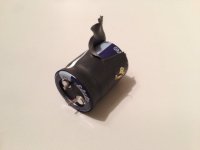
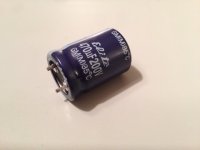
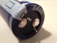
I next removed the large cap next to the wire-wound inductor. It was suspect because it had a green "passed QC" sticker on it- who would put a sticker like that on a component if it weren't prone to fail??? I've heard about ESR "equivalent series resistance" testing for caps, but don't have an ESR meter so I took it off of the board and tested it as best I could with a multimeter. It was not bulging, but I've heard (read on the net) that some caps fail without bulging. Here are the tests I performed on the multimeter-
Test 1- did it have the indicated capacitance? yes it did
Test 2- when discharged, did the resistance on the meter rise from 0 to 500K ohms? yes it did
Test 3- charge it to 12 V and see if it holds it overnight, it lost about 0.5V, seems ok to me
I then thought about it, and realized that a large cap next to a wire wound inductor both located near where the DC charge current exits the charger to connect to the battery being charged was likely part of the DC-DC buck converter to smooth out the voltage on the charge line. That shouldn't make it take "longer and longer" to turn on, so I soldered it back on the board with a longer sigh.
I could have given up at this point, but I'm a member of the Sphere, and by God, I'm not done with it yet.
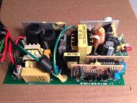
Now I looked over to the side of the board where power comes in from the wall. Sure enough, two large caps wired in series (upper left of board in first photo) were connected to the red wire from the wall. Now this could be the problem! They were wrapped in black heat shrink, but showed no signs of high heat exposure or bulging. I removed both of them and subjected them to the same tests 1,2 and 3 mentioned above and they performed well. I'm guessing that these caps take a lot of current so two identical caps are used in series to produce half the capacitance with more "robust" performance. I think AC current is supposed to pass right through caps, so these must be some kind of filter. I can't come up with a reason why they would cause it to take so long for the charger to turn on, but I still suspect one or both may be the problem.
So, if anyone is still reading, what are your thoughts?
A. you really should get an ESR meter because your cap tests are meanignless/somewhat meaningless/useful but not conclusive...
B. those caps aren't likely to be the problem, but ____ is probably what is wrong...
C. just buy another charger for $115 from Justin and call it a day while doubling your charge rate...
D. buy new caps at Digikey/Mouser and whack 'em in, then turn it on...
E. at your level of knowledge, I expect to hear about KFF in the next post...
All who read this post should consider themselves blessed by the mighty solar powered Norfolk pine.
I'm a total amateur, but you might get a laugh out of this. (scroll down for photos)
My 10 year old 36V charger has taken longer and longer to turn on its red power LED after flipping the power switch on. It works perfectly once it does turn on, giving the same 2.1A current it always did, but it takes ten minutes to turn on now so I've decided to open it up and attempt to fix it. It is branded "High Power" and looks just like this one on Justin's site, except mine is rated at 2A of charging current-
http://www.ebikes.ca/shop/ebike-parts/chargers/cg364lim-ez.html
I unscrewed both endcaps but the circuit board would not slide out. I tried heating the aluminum case to expand it, but no luck. Once I removed the sticker on the side (a-hah!), two screw heads appeared- after removing them the circuit board slid out easily.
I figured the problem was likely a bad capacitor, as TVs take "longer and longer" to turn on sometimes and bad caps are the problem. It also seems like a part that fails regularly and has a time constant related to it, unlike, say a resistor. So I expected to find a bulging cap inside, but to no avail! I did find a resistor that had turned the yellow "potting goop" (see photo) brown and it became suspect number one. Now you are familiar with (horrified by) the level of my analysis.
I removed the pictured resistor and tested it with my multimeter- it was 1500 ohms just like the color code "brown green red" specified. I also realized it was connected to the red and yellow/green LED indicators and was probably there to limit current to them. Since these LEDs were still working fine, it really wasn't likely to be the problem so I cleaned the holes with some braid and soldered it back in with a sigh.
I next removed the large cap next to the wire-wound inductor. It was suspect because it had a green "passed QC" sticker on it- who would put a sticker like that on a component if it weren't prone to fail??? I've heard about ESR "equivalent series resistance" testing for caps, but don't have an ESR meter so I took it off of the board and tested it as best I could with a multimeter. It was not bulging, but I've heard (read on the net) that some caps fail without bulging. Here are the tests I performed on the multimeter-
Test 1- did it have the indicated capacitance? yes it did
Test 2- when discharged, did the resistance on the meter rise from 0 to 500K ohms? yes it did
Test 3- charge it to 12 V and see if it holds it overnight, it lost about 0.5V, seems ok to me
I then thought about it, and realized that a large cap next to a wire wound inductor both located near where the DC charge current exits the charger to connect to the battery being charged was likely part of the DC-DC buck converter to smooth out the voltage on the charge line. That shouldn't make it take "longer and longer" to turn on, so I soldered it back on the board with a longer sigh.
I could have given up at this point, but I'm a member of the Sphere, and by God, I'm not done with it yet.
Now I looked over to the side of the board where power comes in from the wall. Sure enough, two large caps wired in series (upper left of board in first photo) were connected to the red wire from the wall. Now this could be the problem! They were wrapped in black heat shrink, but showed no signs of high heat exposure or bulging. I removed both of them and subjected them to the same tests 1,2 and 3 mentioned above and they performed well. I'm guessing that these caps take a lot of current so two identical caps are used in series to produce half the capacitance with more "robust" performance. I think AC current is supposed to pass right through caps, so these must be some kind of filter. I can't come up with a reason why they would cause it to take so long for the charger to turn on, but I still suspect one or both may be the problem.
So, if anyone is still reading, what are your thoughts?
A. you really should get an ESR meter because your cap tests are meanignless/somewhat meaningless/useful but not conclusive...
B. those caps aren't likely to be the problem, but ____ is probably what is wrong...
C. just buy another charger for $115 from Justin and call it a day while doubling your charge rate...
D. buy new caps at Digikey/Mouser and whack 'em in, then turn it on...
E. at your level of knowledge, I expect to hear about KFF in the next post...
All who read this post should consider themselves blessed by the mighty solar powered Norfolk pine.
")


