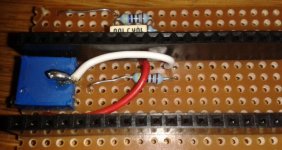
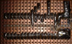
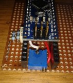
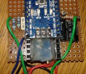
gwhy!1
100 kW
Arduino code for throttle interface that allows current and phase limiting to be pre set. Original code was by Hornet Dave for use with RC controllers : original thread is here http://endless-sphere.com/forums/viewtopic.php?f=30&t=33947
EDIT: A link to my watt/volt meter that can also use this code http://endless-sphere.com/forums/viewtopic.php?f=2&t=61407
this was his original code:
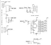
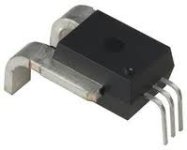
I took Daves code and modified it slightly for use with a ebike controller, instead of a current shunt I use a hall current sensor for current monitoring:
un-rem (rc esc) sections and rem (e-bike) sections for rc esc controller.
Edit :
The code now includes throttle battery/phase control , I am still testing the addition code at the moment (throttle current/phase controller) , initial results are good.
The above code is stripped out of my full code from my throttle interface, and I have not tested this code above as a stand alone controller but as far as I can see all the relevant parts are there and it should work the same as my full code in my interface.
EDIT: A link to my watt/volt meter that can also use this code http://endless-sphere.com/forums/viewtopic.php?f=2&t=61407
this was his original code:
Code:
// winch_a by Dave Wolfe
// this is a work in progress R/C ESC interface that is intended to control
// phase current and battery current.
// This example code is in the public domain.


#include <Servo.h>

Servo myservo; // create servo object to control a servo
// a maximum of eight servo objects can be created

int throttleOut = 1000; // variable to store the servo position
int throttleReq = 1150; // the throttle setting requested by user via pedal
int throttleCurrent = 0; // throttle setting to achieve current limit
int throttlePhase = 0; // throttle setting to achieve phase current limit
long phaseCurrent = 0; // phase current variable; 10X actual
int buttonState = 0; // variable for reading the pushbutton status
long current = 0; // variable for current from shuntInputPin

const int throttleZero = 1150; // initialization/zero endpoint for controller
const int throttleMin = 1245; // min setting for current or phase-current limited
// throttle output, microseconds
const int throttleMax = 1900; // max throttle output, microseconds

const int currentMax = 400; // maximum current *10 (set to 400 for 40 amps)
const int currentGain = 25; // proportional gain setting for current limiting

const int phaseMax = 300; // maximum phase current *10 (set to 900 for 90 amps)
const int phaseGain = 6; // proportional gain for phase current limiting

const long currentScaling = 110; // adjust this so current is 10X actual current
const long currentOffset = 28; // corrects for min shunt voltage not being zero
const int buttonPin = 10; // the number of the pin for the input on/off switch
const int shuntInputPin = A0; // analog input pin from current monitor (shunt)

void setup()
{
myservo.attach(4); // attaches the servo on pin 4 to the servo object
Serial.begin(9600);
// initialize the pushbutton (pedal) pin as an input:
pinMode(buttonPin, INPUT);
}


void loop()
{
// read the amplified shunt voltage from the current monitor, scale it, offset it
// (i should probably offset the raw input and then scale it rather than what i've done..)
current = (analogRead(shuntInputPin) * currentScaling / 100) - currentOffset;
current = max(0,current); // do not allow negative currents, it causes errors later!


// this converts the pedal taps to a throttle signal.
// for an ebike, replace this with a routine to read your throttle
buttonState = digitalRead(buttonPin);
if (buttonState == HIGH)
{
throttleReq += 10; // 10
throttleReq = min(throttleReq,throttleMax);
// throttleReq = min(throttleReq,1300);
}
else
{
throttleReq -= 14; //14
throttleReq = max(throttleReq,throttleZero);
}
// end of the throttle input routine


// this routine computes the throttle output required for current control
throttleCurrent = throttleOut - currentGain*(current - currentMax)/100;
throttleCurrent = max(throttleCurrent,throttleMin);

// compute the phase current phase current = shunt current/throttle
phaseCurrent = current * (throttleMax - throttleMin)/max((throttleOut - throttleMin),20); //set last term to be appx 2.5% of throttle max - throttle min
throttlePhase = throttleOut - phaseGain*(phaseCurrent - phaseMax)/100;
throttlePhase = max(throttlePhase,throttleMin);


throttleCurrent = min(throttleCurrent,throttlePhase); //choose lower of phase or current throttle
throttleOut = min(throttleReq,throttleCurrent); // use the lower of current-limited or user requested throttle value
myservo.writeMicroseconds(throttleOut); // tell servo to go to position in variable 'pos'
delay(15); // waits 15ms for the servo to reach the position
// (not very elegant, I should synch this with the RC throttle signal frequency somehow)


// DEBUG! Pick whatever variables you want to see, use the Arduino serial monitor
// to view your values in real time. Tools -> Serial Monitor

// Serial.print("position:");
Serial.print(throttleOut);
Serial.print(" ");
// Serial.print(", pc:");
Serial.println(phaseCurrent);
// Serial.println(current);

}
I took Daves code and modified it slightly for use with a ebike controller, instead of a current shunt I use a hall current sensor for current monitoring:
un-rem (rc esc) sections and rem (e-bike) sections for rc esc controller.
Code:
// original code by Dave Wolfe on ES.
// modiffied by Gwhy! on ES for use with a e-bike throttle into a e-bike controller
// also added a pot to set max phase current and battery current.
// uses a hall Current sensor instead of shunt.
// This example code is in the public domain.

// set servo for 1.1ms min - 1.8ms max ( or auto range )
/********************************************************
 * A7 (throttle input)
 * A6 (current pot input)
 * A5 (Isensor input)
 * D3 (control) (throttle output) , RC filter is required on output for e-bike controller,, no rc filter for rc esc
 *******************************************************/

// #include <Servo.h>   //  (rc esc)

const int Throttle_Input_pin = 7;  // Throttle input A7
const int Pot_Input_pin = 6;   //Pot input A6
const int Isensor_Input_pin = 5;  //Isensor input A5
const int Throttle_Output_pin = 3;  //Throttle output D3.. RC filter need is e-bike controller .. no RC filter for rcesc

//const int Set_Min_Servo = 1000;  // esc start with this as min throttle  // (rc esc)
//const int Set_Max_Servo = 1800;  // esc end with this as max throttle  // (rc esc)
//int Servo_time = 1000;   // (rc esc)


long phaseCurrent = 0; // phase current variable;
const int currentGain = 25; // (25 default) proportional gain setting for current limiting // this value sets how fast the system reacts to throttle input, to high a value causes oscillation around the setpoint , so need to be mess around with to optimize , same with phasegain value.
const int phaseGain = 6; // (6 default)proportional gain for phase current limiting
//const float Current_pot = 512; // un-rem to use a hard codded current limit ( 0-1023 = 0A upto the value of current sensor)
int Sensor_Cal = 512; // grab real value of this is set in setup section
int throttleCurrent = 0; // throttle setting to achieve current limit
int throttlePhase = 0; // throttle setting to achieve phase current limit
int phaseMax = 0;
int max_throttleOut = 1023;
int Throttle_Value=0;
int Throttle_Pulse=0;
int Set_Throt_Min = 55; // this needs to be the min value to remove dead band from throttle output , around 55
int Set_Throt_Max = 180; // this needs to be the max value to achive full throttle without cutting out , around 180
int Cal_Throt_Min = 176; // this needs to be set to the real value of the throttle when fully closed;
int Cal_Throt_Max = 842; // this needs to be set to the real value of the throttle when fully open;
float SensorRT=1023; // variable to store value of current sensor.
float Current_pot=0;  // variable to store value that sets max current/phase limit. //rem out.. if using hard coded current limits

void setup()
{ //--- initialize serial communication at 9600 bits per second:
   Serial.begin(9600);
// initialize the variables we're linked to
   pinMode(Throttle_Output_pin, OUTPUT);   // sets the D3 pin as output // (e-bike)
   analogWrite(Throttle_Output_pin,0);  // (e-bike)

   // Servo_Pulse.attach(6);      // Attach Servo_Pulse to pin 3  //  (rc esc)
   // Servo_Pulse.writeMicroseconds(Servo_time);  //  (rc esc)

   delay(1000);
   Sensor_Cal = analogRead(Isensor_Input_pin); // grabs offset of current sensor that must be connected at power up or the code will not funtion corectly.

}

void loop()
{
// throttle, pot, raw current reading/offsetting
Throttle_Value = analogRead(Throttle_Input_pin);
Throttle_Pulse = constrain(map(Throttle_Value,Cal_Throt_Min,Cal_Throt_Max,0,1023),0,1023); // set range on throttle and zero's throttle value
Current_pot = constrain(analogRead(Pot_Input_pin),0,1023); // rem out.. if this value is hard coded to speed things up a bit and to free up a adc input
SensorRT = map(analogRead(Isensor_Input_pin)- Sensor_Cal ,0,1023-Sensor_Cal,0,1023);
SensorRT = max(0,SensorRT);

Current_pot = (Throttle_Pulse*Current_pot)/1023; // use current pot to set overall max power%
phaseMax = Current_pot*2;
Throttle_Pulse=max(Throttle_Pulse,120); // Throttle pulse uses highest value
if (Current_pot < 2)  max_throttleOut=0;  // stop jitter and reset throttle value


// this routine computes the throttle output required for current control
throttleCurrent = max_throttleOut - currentGain*(SensorRT - Current_pot)/100;
throttleCurrent = max(throttleCurrent,0);

// compute the phase current phase current = shunt current/throttle
phaseCurrent = SensorRT * 1023 /max(max_throttleOut,25); //set last term to be appx 2.5% of throttle max - throttle min
throttlePhase = max_throttleOut - phaseGain*(phaseCurrent - phaseMax)/100;
throttlePhase = max(throttlePhase,0);

throttleCurrent = min(throttleCurrent,throttlePhase); //choose lower of phase or current throttle
max_throttleOut = min(Throttle_Pulse,throttleCurrent); // use the lower of current-limited or user requested throttle value

Throttle_Pulse = map(max_throttleOut,0,1023, Set_Throt_Min, Set_Throt_Max);// scale throttle output limits
analogWrite(Throttle_Output_pin,Throttle_Pulse);  // write throttle to controller //  (e-bike)

//Servo_time = map(max_throttleOut,0,1023,Set_Min_Servo,Set_Max_Servo); // scale output   //  (rc esc)
//Servo_Pulse.writeMicroseconds(Servo_time); //output servo signal to controller  //  (rc esc)


// DEBUG! Pick whatever variables you want to see, use the Arduino serial monitor
// to view your values in real time. Tools -> Serial Monitor


//Serial.print(throttlePhase);
//Serial.print("  ");
//Serial.print(Throttle_Pulse);
//Serial.print("  ");
//Serial.print(SensorRT);
//Serial.print("  ");
//Serial.print(Current_pot);
//Serial.print("  ");
//Serial.println(max_throttleOut);
}
Edit :
The code now includes throttle battery/phase control , I am still testing the addition code at the moment (throttle current/phase controller) , initial results are good.
The above code is stripped out of my full code from my throttle interface, and I have not tested this code above as a stand alone controller but as far as I can see all the relevant parts are there and it should work the same as my full code in my interface.


