watt meter all functions (diy)

gwhy!1

100 kW
Joined
Jun 8, 2011
Messages
1,652
Location
Bristol, Uk
I thought I would start a thread for anyone interested in adding to a generic watt meter project based around the arduino nano. This is a follow on from this thread http://endless-sphere.com/forums/viewtopic.php?f=2&t=61004

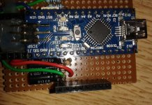
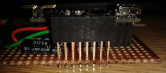
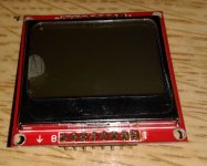
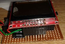
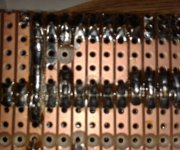
I have added a screen to the vero layout in the other thread I will take some pics and post them up with the details soon.
 
Code:
/********************************************************
 * D2 - lcd backlight
 * D4 - Serial clock out (SCLK)
 * D5 - Serial data out (DIN)
 * D6 - Data/Command select (D/C)
 * D7 - LCD chip select (CS)
 * D8 - LCD reset (RST)

 *******************************************************/


//******Display  nokia  config******
#include <Adafruit_GFX.h>
#include <Adafruit_PCD8544.h>
#define BackLight 2
Adafruit_PCD8544 display = Adafruit_PCD8544(4, 5, 6, 7, 8);
//**********************************

void setup()
{ //--- initialize serial communication at 9600 bits per second:
   Serial.begin(9600); 
// initialize the variables we're linked to
   pinMode(BackLight,OUTPUT);
   digitalWrite(BackLight,LOW); // back light ON


   display.begin(60);  // Initialize lcd (default contrast 50-60)
   display.clearDisplay();   // clears the screen and buffer 
   display.setTextSize(1);
   display.setCursor(4, 25);
   display.println("DIY");
   display.setCursor(4, 35);
   display.println("INITIALIZING");
   display.display();
   delay(2000);

}

void loop()
{

   display.clearDisplay();   // clears the screen and buffer 
   display.setTextSize(1);
   display.setCursor(0, 0);
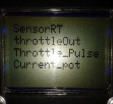
   display.println("SensorRT");
   display.setCursor(0, 10);
   display.println("throttleOut");
   display.setCursor(0, 20);
   display.println("Throttle_Pulse");
   display.setCursor(0, 30);
   display.println("Current_pot");
   display.display();

}
this code is a starting point and will run the display as is.
the code can be added to the code in the other thread ( http://endless-sphere.com/forums/viewtopic.php?f=2&t=61004 ) to add a display to the throttle interface.
this is a follow on from the other thread.
lcd nokia socket.jpg
lcd nokia socket_.jpg
lcd nokia.jpg
lcd nokia_fitted.jpg
lcd nokia socket_bottom.jpg
 
this is the combined code for the display.
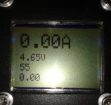
Added realtime current readout from hall current sensor, also displays arduino supply voltage.

Code:
//ES use with a e-bike throttle into a e-bike controller 
// also added a pot to set max phase current and battery current.
// uses a hall Current sensor instead of shunt.
// This example code is in the public domain.

// set servo for 1.1ms min - 1.8ms max ( or auto range )
/********************************************************
 * A7 (throttle input)
 * A6 (current pot input)
 * A5 (Isensor input)
 * A4 (battery input )
 * D2 - lcd backlight
 * D3 - (control) (throttle output) , RC filter is required on output for e-bike controller,, no rc filter for rc esc 
 * D4 - Serial clock out (SCLK)
 * D5 - Serial data out (DIN)
 * D6 - Data/Command select (D/C)
 * D7 - LCD chip select (CS)
 * D8 - LCD reset (RST)

 *******************************************************/

// #include <Servo.h>   //  (rc esc)

//******Display  nokia  config******
#include <Adafruit_GFX.h>
#include <Adafruit_PCD8544.h>
#define BackLight 2
Adafruit_PCD8544 display = Adafruit_PCD8544(4, 5, 6, 7, 8);
//**********************************

const int Throttle_Input_pin = 7;  // Throttle input A7
const int Pot_Input_pin = 6;   //Pot input A6
const int Isensor_Input_pin = 5;  //Isensor input A5
const int Voltage_Input_pin = 4;  //battery voltage input A4
const int Throttle_Output_pin = 3;  //Throttle output D3.. RC filter need is e-bike controller .. no RC filter for rcesc 

//const int Set_Min_Servo = 1000;  // esc start with this as min throttle  // (rc esc)
//const int Set_Max_Servo = 1800;  // esc end with this as max throttle  // (rc esc)
//int Servo_time = 1000;   // (rc esc)                                                 


long phaseCurrent = 0; // phase current variable; 
const int currentGain = 25; // (25 default) proportional gain setting for current limiting
const int phaseGain = 6; // (6 default)proportional gain for phase current limiting

const int  sensor_spec = 20.0; //20.0 = 200A sensor... 26.7 (27.0)= 150A sensor.... 10.0 = 100A sensor
 
//const float Current_pot = 512; // un-rem to use a hard codded current limit ( 0-1023 = 0A upto the value of current sensor) 
int Sensor_Cal = 512; // grab real value of this is set in setup section
int throttleCurrent = 0; // throttle setting to achieve current limit
int throttlePhase = 0; // throttle setting to achieve phase current limit
int phaseMax = 0; 
int max_throttleOut = 1023;
int Throttle_Value=0;
int Throttle_Pulse=0;
int Set_Throt_Min = 55; // this needs to be the min value to remove dead band from throttle output , around 55
int Set_Throt_Max = 180; // this needs to be the max value to achieve full throttle without cutting out , around 180
int Cal_Throt_Min = 176; // this needs to be set to the real value of the throttle when fully closed;
int Cal_Throt_Max = 842; // this needs to be set to the real value of the throttle when fully open;

float SensorRT=1023; // variable to store value of current sensor. 
float Current_pot=0;  // variable to store value that sets max current/phase limit. //rem out.. if using pot to set current limits
float Vcc;
float Voltage;
float Battery_Volts; // calculated value voltage reading from the main battery
const float battery_adj = 13; // this is the value from the PD R2/(R1+R2) , the pd should be calculated so appox 5v is across R2 with the max input voltage

float sensor_spec_adj = 0.0 ;
float Current=0;

//******** time variables
float time;
float ampSec;
float ampH;
float msec;
float amphours_time;
float msec_last = 0.0;
//***********************


void setup()
{ //--- initialize serial communication at 9600 bits per second:
   Serial.begin(9600); 
// initialize the variables we're linked to
   pinMode(Throttle_Output_pin, OUTPUT);   // sets the D3 pin as output // (e-bike)
   analogWrite(Throttle_Output_pin,0);  // (e-bike)
   
   // Servo_Pulse.attach(3);      // Attach Servo_Pulse to pin 3  //  (rc esc)
   // Servo_Pulse.writeMicroseconds(Servo_time);  //  (rc esc)

   pinMode(BackLight,OUTPUT);
   digitalWrite(BackLight,LOW); // back light ON
   
   delay(1000);
   Sensor_Cal = analogRead(Isensor_Input_pin); // grabs offset of current sensor that must be connected at power up or the code will not funtion corectly.

   display.begin(60);  // Initialize lcd (default contrast 50-60)
   display.clearDisplay();   // clears the screen and buffer 
   display.setTextSize(1);
   display.setCursor(4, 25);
   display.println("DIY");
   display.setCursor(4, 35);
   display.println("INITIALIZING");
   display.display();
   delay(2000);
Vcc = readVcc()/1000.0;  // read actual arduino supply voltage;
sensor_spec_adj = ((Vcc-5)*sensor_spec / 5) +sensor_spec; // cal error factor of current sensor

}

void loop()
{
  
// throttle, pot, raw current reading/offsetting
Throttle_Value = analogRead(Throttle_Input_pin);
Throttle_Pulse = constrain(map(Throttle_Value,Cal_Throt_Min,Cal_Throt_Max,0,1023),0,1023); // set range on throttle and zero's throttle value
Current_pot = constrain(analogRead(Pot_Input_pin),0,1023); // rem out.. if this value is hard coded to speed things up a bit and to free up a adc input
SensorRT = map(analogRead(Isensor_Input_pin)- Sensor_Cal ,0,1023-Sensor_Cal,0,1023); 
SensorRT = max(0,SensorRT);

Current_pot = (Throttle_Pulse*Current_pot)/1023; // use current pot to set overall max power% 
phaseMax = Current_pot*2; 
      Throttle_Pulse=max(Throttle_Pulse,120); // Throttle pulse uses highest value 
      if (Current_pot < 2)  max_throttleOut=0;  // stop jitter and reset throttle value


// this routine computes the throttle output required for current control
throttleCurrent = max_throttleOut - currentGain*(SensorRT - Current_pot)/100;
throttleCurrent = max(throttleCurrent,0);

// compute the phase current phase current = shunt current/throttle
phaseCurrent = SensorRT * 1023 /max(max_throttleOut,25); //set last term to be appx 2.5% of throttle max - throttle min
throttlePhase = max_throttleOut - phaseGain*(phaseCurrent - phaseMax)/100;
throttlePhase = max(throttlePhase,0);

throttleCurrent = min(throttleCurrent,throttlePhase); //choose lower of phase or current throttle
max_throttleOut = min(Throttle_Pulse,throttleCurrent); // use the lower of current-limited or user requested throttle value

Throttle_Pulse = map(max_throttleOut,0,1023, Set_Throt_Min, Set_Throt_Max);// scale throttle output limits  
analogWrite(Throttle_Output_pin,Throttle_Pulse);  // write throttle to controller //  (e-bike)

//Servo_time = map(max_throttleOut,0,1023,Set_Min_Servo,Set_Max_Servo); // scale output   //  (rc esc)
//Servo_Pulse.writeMicroseconds(Servo_time); //output servo signal to controller  //  (rc esc)   


// DEBUG! 
Vcc = readVcc()/1000.0;  // read actual arduino supply voltage;
Current = (SensorRT*Vcc) / sensor_spec_adj; // calc current to display
Battery_Volts = (( analogRead(Voltage_Input_pin) * Vcc )/1023)*battery_adj;

//------------ amp hour routine start
   msec = (millis() - msec_last) ; 
   time = (float) msec / 1000.0;
   ampSec = Current*time;
   amphours_time = ampSec/3600;
   ampH = ampH + amphours_time;
   msec_last = millis();
//-----------------------------      


   display.clearDisplay();   // clears the screen and buffer 
   display.setTextSize(2);
   display.setCursor(0, 0);
   display.print(Current);
   display.println("A");
   display.setCursor(0, 17);
   display.print(Battery_Volts);
   display.println("V"); 
   display.setCursor(0, 34);
  display.print(ampH);
  display.println("Ah"); 
   display.display();
   
}

//---   read 5v supply voltage using the 1.1v reference
long readVcc()
{ long result;
  ADMUX = _BV(REFS0) | _BV(MUX3) | _BV(MUX2) | _BV(MUX1);
  delay(2); // Wait for Vref to settle
  ADCSRA |= _BV(ADSC); // Convert
  while (bit_is_set(ADCSRA,ADSC));
  result = ADCL;
  result |= ADCH<<8;
  result = 1125300L / result; 
  return result;
}

amp readout.jpg
 
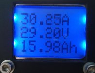
Added the PD to a arduino analog input A4 to measure the main battery voltage.

updated above code now includes realtime battery volts and amphours.

VAAH.jpg

So that your basic watt meter that includes a current controlled throttle for a e-bike controller or a RC esc controller. The arduino has 5 addition digital inputs/outputs to play with and also 4 addition analog inputs not in use so there is plenty of scope to add lots of nice features , rpm,temp,buttons,leds,cutouts,locks,bluetooth ..
 
if you add a couple of buttons you can do some stuff without a pc, or even add bluetooth and program it through a android device.
 
you could just program your very own cycle analyst ;)
what the max voltage the arduino can measure? i guess i will just order another one just to play a little more. there are so many things to do. normally i have those single/dual amp/voltmeters installed in my charger's cass, but the arduino with display looks even better.
and if we find a weatherproof case for the display it could be installed on the bike.
 
the max voltage that it can measure will depend on the PD on pin A4 the values i have chosen for this is 56k and a 4.7k this can handle a max voltage input of 65v. but other values can be selected for the PD i.e if you used a 120k and a 4.7k then the max voltage will be around 120v .
 
you can make the screen opening weather proof by sticking a piece of weather proof clear plastic over the hole.. weather proofing switches is a little more tricky, but you can do what I have done with one of my devices and have a tiny little remote button box ( 2 buttons ) that plugs into the meter when needed..
 
sure. i thought the voltage would be measured directly. but of course you only need to lower it with a resistor :)
i found many intersting hardware parts to add, ranging from bluetooth to relais and gyroscope/ acceleration meters and gps modules. a lot of nice thing to do with them.
they cost next to nothing, but cases etc cost twice as much as a ardiuno board?!
 
izeman said:
do we need a rtc as well? or is the time calculated internally?

no its all done on board the arduino.

so parts needed:
1x arduino nano approx £5
1x nokia 5110 lcd display approx £2
1x hall current sensor approx£7
the resistors, caps, vero board, pcb sockets, wire and a box to put it all in. approx £4

if you wanted to add a BT module approx £6

and what ever plugs and sockets you need to connect it to the outside world.

and if you want to power it from your main battery you will need a dc-dc converter approx £3
 
oh man. i ordered at least 3x that much :) two arduinos and two displays in case i short something. 2 current sensor as the first one was 50a only, until i found out that you measure phase amps and this would be around 100a max.
resistors i have at home as well as most caps. vero board with wires (male and female connectors) was ordered.
what pcb sockets would i need?
dc around 8.5v is already there to power the led light.
 
izeman said:
oh man. i ordered at least 3x that much :) two arduinos and two displays in case i short something. 2 current sensor as the first one was 50a only, until i found out that you measure phase amps and this would be around 100a max.
resistors i have at home as well as most caps. vero board with wires (male and female connectors) was ordered.
what pcb sockets would i need?
dc around 8.5v is already there to power the led light.

:D that always the way..

the phase amps is calculated from the battery amps so a 50A sensor will do the job..

8.5v will be useable but you will need to connect it to the Vin pin ( 6-18v input )and then not connect the throttle +5v at the throttle plug where it goes into the controller.
2x female 20way pcb header for the arduino (if you want to copy my layout) and 1x female 8way extended pcb headers for the display.

Cornwall, nice. Hope the weather is holding up for you .
 
izeman said:
ok. pin headers. have them as well. so you're measuring battery? why not phase? wouldn't that be more precise?
and would it be better to power the arduino with 5v?
and yes: the weather is great. sunshine all day long!

Vin on the nano has a 5v regulator built in to power the whole board so it do not really matter it will accept anything around 6v-18v on this pin and regulate it to around 5v to power the rest of the circuit . the only thing I have found with using the onboard 5v reg is that it regs at around 5.5v ( which is fine for 99% of stuff ) but the nokia displays have a very much reduced life if run @ 5v or higher, having said that I have not had one bust on me yet, not from over volting anyway I like to run my arduinos with around 4.7v this way everything is happy. so if you have got a 5v supply then you can use that I will see how well the compete thing works of of the throttle supply of the controller even though this is around 4.4v it should be fine ( well it was without the nokia display connected ) the display only draws around 3 or 4 mA max so I think it will still be fine but until i test i cant be sure. You will need some capable current sensors to measure phase current directly the cost and logistics are also a issue. Measuring the battery current works rather well and calculating the phase current , its not perfect but its 100% better than guessing :mrgreen: when you get you meter up and running get it to display the calulated phase current and compare it with a clamp on amp meter on the phase wires.
 
izeman said:
how would you calculate phase amps from battery amps? yes the 200a chip is about double the price of the 50a one. i'm not sure if it will make a big difference though as battery and phase amp both are zero at a full stop and are the same at wot.

phase currents can be massive (100's) of amps , max phase current happens more of less the second you open the throttle and then more or less become equal at mid throttle.
 
izeman said:
that's why i thought it would maybe better to monitor phase amps. at least this is what i would need with a quite torquey mid drive. those are imho the most delicate to deal with regarding a smooth start on steep hill.

The phase current is calculated from battery amps and pwm (throttle output value ) at any given time , and for the most part its not to far off. It can be done with battery current only but due to the magnitude of the differences between battery and phase at the slower speed this is more tricky to get very smooth low throttle control.. it can be done but its also nice to keep the phase current under control as well as the battery current.
 
i updated the A,V, and Ah display a bit. it all double digit with one digit after the comma.
maybe someone can use it:

Code:
   display.clearDisplay();  // clears the screen and buffer 
   display.setTextSize(2);
   display.setCursor(0, 0);
   if(Current <10) display.print("0"); // add leading 0 if <10
   display.print(Current,1);
   display.println(" A");
   display.setCursor(0, 16);
   display.print(Battery_Volts,1);
   display.println(" V"); 
   display.setCursor(0, 32);
   if(ampH <10) display.print("0"); // add leading 0 if <10
   display.print(ampH,1);
   display.println(" Ah"); 
   display.display();
 
Thanks for this info. I'm doing a rc mid drive and will program an arduino nano, also have a LCD shield but I've had trouble writing to it. My goal is basic throttle ramp, ebrake, thermal roll back, LVC, LCD display of volt,speed,temperature. Or a few LEDs to do the same; warning light style , rgb LEDs.
 
Back
Top