9C Hubmotor: Parallel/Series Switch (Star/Star)

Ferreira

10 mW
Joined
Sep 3, 2014
Messages
30
Location
Florianópolis S.C., Brazil
Hello all!

I modified my motor to be able to climb a hill of ca. 25% grade of ca.200m length, which I encounter at the end of virtually each and every of my rides, and which destroys most of the joy I have with my bike.

Motor and controller of my bike (Daytona, scooterbrasil.com.br) are from Nine Continent. The motor is a JZ48V800W12051000003 (48V, 800W, 120°, 51 poles, I guess). The three coils form a star and each coil is wound with nine parallel wires (AWG22).

Having seen various modifications on youtube and in forums like this one, I opened the motor and divided the three coils into nine coils with three parallel wires. The eighteen ends of the nine coils are lead through the axis (AWG17) where six double selector switches allow me to connect either a star with three parallel coils per branch (original) or a star with three coils in series per branch (high torque/low speed).

SternStern.jpg
Parallel wiring / wiring in series


View attachment 6
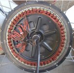
Motor before modification. At 12hrs the three phases, at 2hrs the star point.
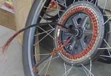


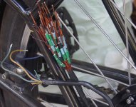
Herausführung.jpg
18x AWG17 plus 5x hookup wire for the hall sensors.​


MotorNachher.jpg
Motor after modification.


Farbcodes.jpg
Wires lead outside marked with color codes.
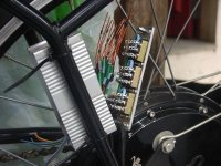


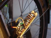
Schalter.jpg
The switches (normally used for 110V/220V switching) 10A/120V 5A/250V. Hopefully 15A/48V. Max. 20mΩ. Measured 7...8mΩ.​


Verdrahtet.jpg
Wiring done.


Thank God, everything worked out fine.

Using the parallel mode the bike apparently behaves like before, although there now are additional copper losses as well as losses in the switches which each are around 2% of the battery power (4x 12V 10Ah lead-gel) in the case of high load, and below 1% in typical operation. Using the series mode, the idle speed, which is reached when the back-EMF reaches the controller voltage, apparently is three times lower.

I used the ebikes.ca simulator to determine that the bike climbs 9% grade at 24km/h. Using the series mode, it now should climb 27% at 8km/h. But it does not. The reason is, that in series mode the nominal voltage of the controller should be tripled (144V) while the controller pumps only a third of Amps through the motor and the losses stay the same. I tripled the motor constant, so with three times higher torque at three times lower speed I will need three times higher voltage at three times lower current.

Modelling the Motor as U = R + jωL + Uemf, in series mode R is nine times higher, L is nine times higher, and Uemf is three times higher. Therefore 48V is not enough when climbing a 27% grade at 8km/h.

The simulator says that climbing a 9% grade at 24km/h in parallel mode happens at 45A (controller limits battery current to 22A). Therefore a 27% grade at 8km/h in series mode needs 15A. My calculations (using R = 0.1Ω, L = 0.2mH in parallel mode, R = 0.9Ω, L = 1.8mH in series mode) say that a minimum of 62,2V is required for the controller to be able to feed 15A at this operating point. Thus, having 60V, using a fifth battery (which I have), I should be able to climb the 27% grade at less than 8km/h but more than 5km/h, which would solve my problem.

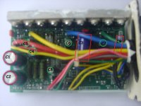
But how will the controller behave with 60V instead of 48V batteries? Here's a picture of my controller:

View attachment 1

A Nine Continent "Intelligent Infineon E-Bike-Controller". Voltage is 48V. Max. battery current is 22A.

Which modifications are necessary to use the Controller with 60V batteries?
Current should be no problem, in series mode it is three times lower in all cases, including the worst case.
I will have to check the MOSFETs' voltage ratings.

What else do I have to consider, when using 60V? Thanks in advance for helpful comments!
 
Today I took a closer look at the controller. On the outside it says

Code:
Nine Continent
Intelligent Infineon E-Bike Controller
Model  ▢60V ▣48V ▢36V ▢24V
...
Low Voltage Protect ▢31,5V ▣42V ▢52V
Max current 22A
Thus I assume that replacing some parts will allow to use it with 60V.

Opening the casing I found the board labelled C-TC2.1 on both sides. Also on the lead side it says FF20 as well as 0-008. Whatever that means.

It has 9 MOSFETs labelled P75NF75&. That's a 75V/10mΩ type. So I think it won't be too big a risk to operate them with 5x12V sealed lead acid batteries.

Then I took a look at the capacitors:

Bestückungsseite.jpg
Sorry for the bad quality! (That's about the way I see things from a small distance without glasses.) Here it just serves to name the electrolytic capacitors. I marked those capacitors red, which I think must be replaced. All marked capacitors are SLF-series capacitors 105°C. Labels are mine and not found on the board.

C1 and C2 are 470µF/63V and wired parallel to the battery. I will replace them with at least 80V types. Their diameter is smaller than that of the white rings printed on the board.
C3 is 470µF/63V. I didn't find out the wiring. I will replace it with an at least 80V type.
C4 is 470µF/25V. It is wired from the input (pin 1) of a 78LS05 voltage regulator to ground. I will leave it unchanged. (circuit see below)
C5, C6 and C7 are 47µF/50V. Their negative pins are connected to the phase-wires U/V/W. Their positive pins are connected to a diode such that they can be loaded via the diode. I didn't so far find out which purpose they serve. The diameter corresponds to the diameter of the white rings printed on the board. I plan to risk not to replace them.
C8 is 220µF/16V and wired from the output (pin 3) of the said 78LS05 voltage regulator to ground. I will leave it unchanged.
C9 is 47µF/63V. I didn't find out the wiring. I will replace it with an at least 80V type.

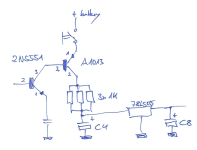
5V-Spannungsversorgung.png
This is part of the circuit to feed the 78LS05. To me it looks like I don't have to change the resistors for 60V operation, the transistors look like they are placed there to keep losses in the three parallel 1kΩ-resistors low.

I kindly ask those readers who have experience in the field, BLDC controllers, Nine Continent or similar controllers, maybe even this particular controller, to take a look at this and warn me, give hints etc., if I am wrong in some point or there are more things to consider, or how can I change the low voltage protection level etc.
 
When opening the controller, the following problem occured: The 5 lateral screws (Phillips recessed head) were full of glue. They were hard to unscrew. As the glue was obstructing the screw-driver to fully enter, I destroyed the heads of two of them. Then I used a hacksaw to transform them into slotted screws, which solved the problem. I recommend to first remove the glue to avoid such problems, though I don't know of an elegant way to remove the glue.
 
Just a heads-up, having personally experienced various failures of that kind of switch in various experimental bicycle use:

That type of switch is probably not a good choice. If those are the kind they look like, open-frame slide switches, they could easily make/break under vibration, and water or other contaminants could easily get in there to cause make or break, unless you have a good seal across the fronts of the switches.

If it happens while you're riding, consequences could vary from absolutely none to power failure to arcing in the switches to damaged FETs to partial braking to a wheel lockup, depending on how things are wired and if any shorts occur.

Another issue is that those switches aren't rated for very high currents, but you could see quite high phase currents thru them during startup from a stop, or other high-acceleration. (can be many times battery current because of PWM in the controller). With the high currents at those voltages thru the switches' resistances, it could cause enough heating at the little slide contacts that over time it could deform the thin slide piece, causing even higher resistance and further heating, etc. It depends on how well-cooled the switch bank is. (if the switch bank is inside that case to prevent contaminant-ingress, it will not have a lot (or any) air cooling, and if it's air-cooled it probably will end up with contaminants).


Regarding battery vs controller voltage: If it is a "48V" controller, it's usually already setup to do "60V" as that is about what full-charge on most "48V" batteries is, such as 4x 12V SLA in series.

But if you are talking about 60V as in 5x 12V SLA in series, then that's more like 72V fully charged, and you would probably want a controller rated for 100V to safely handle that with a good margin for "oops".


If you're not sure, you'd want to look at the various controller upgrade / modification / overclock / boost threads, to see what people have had to do when they did this. There may be links to some of them in hte ES wiki.

Sometimes it's very easy to do and cheap (replacing a couple big caps and maybe a resistor on the low-voltage regulator input), and sometimes it's worth getting a new controller for all the cost and hassle (replacing all the big caps and the FETs, figuring out and redesigning or recalculating stuff on the low-voltage regulator, possibly replacing some of the small caps, etc).
 
@amberwolf

Thank you for your comments!


amberwolf said:
Just a heads-up, having personally experienced various failures of that kind of switch in various experimental bicycle use:

That type of switch is probably not a good choice. If those are the kind they look like, open-frame slide switches, they could easily make/break under vibration, and water or other contaminants could easily get in there to cause make or break, unless you have a good seal across the fronts of the switches.

If it happens while you're riding, consequences could vary from absolutely none to power failure to arcing in the switches to damaged FETs to partial braking to a wheel lockup, depending on how things are wired and if any shorts occur.
Yes, I wouldn't want to recommend these switches for daily use either. Here is a better image:

interruptor-deslizante-serie-hh-metalico-415x415.jpg

My switches are the same, apart from better contacts for 10A/120VCA or 5A/250VCA. In parallel mode in a typical high load situation each switch (7-8mΩ) has to carry 15A of the 45A motor current. It is possible, to stall the bike worse, I have to avoid that. The contacts have "Kontaktpaste". I don't know what that is in english. Like toothpaste for teeth, contactpaste is for contacts. It contains copper.

In series mode currents are lower at higher voltage, thus losses are the same.

I decided to use these switches, because they were cheap and for now I am just experimenting to find out the right motor configuration for my purposes. Beside these switches, the 18x AWG17 wire through the axis in the current configuration is quite a risky thing. I placed some small manufactured pieces of aluminium sheet around the sparingly isolated wires to protect them from the sharp edges at the outlets of the borehole through the axis.


amberwolf said:
Another issue is that those switches aren't rated for very high currents, but you could see quite high phase currents thru them during startup from a stop, or other high-acceleration. (can be many times battery current because of PWM in the controller). With the high currents at those voltages thru the switches' resistances, it could cause enough heating at the little slide contacts that over time it could deform the thin slide piece, causing even higher resistance and further heating, etc. It depends on how well-cooled the switch bank is. (if the switch bank is inside that case to prevent contaminant-ingress, it will not have a lot (or any) air cooling, and if it's air-cooled it probably will end up with contaminants).
Yes, all these risks have to be considered. For experimentation purpose the switches sure are good enough for now. As long as the switches are new and have 7-8mΩ there will be no problem. But sooner or later wear as well as mechanical load, weather etc. will start to worsen the situation.

I assume that in the end I will either use electronic switches or none at all. My first goal now is to make the bike carry me up a 25% grade of 200m length at whatever low speed. After that I may even consider to use the series mode only with an appropriate controller and without rigid copper in the axis.


amberwolf said:
Regarding battery vs controller voltage: If it is a "48V" controller, it's usually already setup to do "60V" as that is about what full-charge on most "48V" batteries is, such as 4x 12V SLA in series.

But if you are talking about 60V as in 5x 12V SLA in series, then that's more like 72V fully charged, and you would probably want a controller rated for 100V to safely handle that with a good margin for "oops".
Yes. Fully charged it's more like 5x 14V or more. There are 5V or less left for the 75V-MOSFETs. In the current state, 4x 14V or more, there are 7V or less left for the 63V-capacitors.


amberwolf said:
If you're not sure, you'd want to look at the various controller upgrade / modification / overclock / boost threads, to see what people have had to do when they did this. There may be links to some of them in hte ES wiki.
I found some help already. But I have no idea how much I did not find so far in this vast forum. To make everything sure, a schematic of my particular controller was necessary, possibly even the software of the µC had to be consulted.


amberwolf said:
Sometimes it's very easy to do and cheap (replacing a couple big caps and maybe a resistor on the low-voltage regulator input), and sometimes it's worth getting a new controller for all the cost and hassle (replacing all the big caps and the FETs, figuring out and redesigning or recalculating stuff on the low-voltage regulator, possibly replacing some of the small caps, etc).
When the bike carries me up the 25% grade, I'll be ready to spend more money (and time if needed). A $125-controller will cost me more like $265 here in Brazil. Same proportion for not extremely common semiconductors. Then I will decide how to proceed. Depending on whether I will keep the parallel/series switching, I will need an appropriate controller, maybe eletronic switches for parallel/series, maybe a self-made integrated solution based on an appropriate controller. In the simplest case I may decide to use only series mode with a +-100V-controller. Other options are open.
 
One thing about the axle and wires, is if you can find a larger bearing, with a large enough inside diameter, you coudl run al lthe wires thru the sidecover itself instead of the axle. You'd have to tiehr make a new sidecover or do some additions to it (bolted on?) to hold the new bearing, plus a "filler" plate for the inside of the bearing tha thas holes for hte wires.


There's a recent thread specifically about motors taht already do this, and there've been discussions aobut modifying motors for this, too. I havent' done it so I don't know how easy it would be, but I have considered it for one of the motors that I have mulitple sidecovers for, as an experiment to run fatter wires and see if it has any effect on performance at startup. :)

(I don't know if I will ever get around ot it, though, cuz I think of lots of things I either never have time for, money for, parts for, or change my plans and don't end up needing to try).
 
Most folks who put lots of copper through the axle do this in a situation where relatively low voltage and high currents are used to increase speed. In most cases current is additionally increased for higher power.

I, on the other hand, do not want to increase power or speed. I want to stay at 1kW, while currents are lowered and voltage is increased, while speed is lowered and torque is increased. So I'd use more available inner axle diameter not for more copper but for more isolation and for more mechanical robustness. The copper I use now (18x AWG17 x 35cm), is heated by 1W typically and 2W under high load, in original normal parallel mode. In series mode, climbing 27% grade, the currents are three times lower and the losses in this same copper are nine times lower.

Beside this, my mechanical workshop and abilities are extremely limited.
 
In the previous post I wrote:

Ferreira said:
In series mode, climbing 27% grade, the currents are three times lower and the losses in this same copper are nine times lower.
That's not true. Whether parallel or in series, each wire carries the same current and the losses are equal.

But still: Staying at 1kW, I have no reason to worry about the 1W or 2W losses. I'd have no problem with offering 10% or more of cruising range to be able to climb those 200m of 25% grade.
 
Different windings won't give you another gearing, just upper the efficiency a tiny bit at the cost of speed.
Some reason there is a missunderstanding that small wheels are beneficial just at very low speed,
a low wind small wheel will allways surpass a higher wind motor in a big wheel!
-So, to get up that hill, stokemonkey style or small wheel is the way to go.
And don't forget the momentum of speed in the base - and from what I understand you have two legs aswell? 200m, hmm
 
esselius said:
Different windings won't give you another gearing
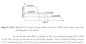
I think, they will:

index.png

Excerpt from from Permanent Magnet Motor Drives with Switched Stator Windings (PhD Thesis, Eckart Nipp, PDF).


esselius said:
from what I understand you have two legs aswell? 200m, hmm
See, I could cut my firewood by hand, too. But I prefer my fuel powered chain saw.

I am over 50, heavy smoker, no sports, no muscles. Sometimes, if the batteries aren't too low and the weather isn't too hot, I make the 200m of average 25% grade (60kg plus 40kg e-bike). But after that I am completely exhausted.
 
My dream, to make 200m of 25% grade with my e-bike without muscular assistance melted away. But my efforts to more easily make the grade seem to be not completely in vain.

I inspected the ebikes.ca simulator and created a Java-implementation of the core algorithm to verify the ideas presented in this thread. I won't publicate my code, I don't intend any disservice to the creators of the ebikes.ca simulator.

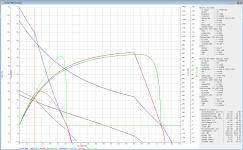
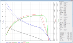
To compare my motor (or at least a similar motor, a 9C 2805) in original parallel star mode to the modified version (serial star mode), I increased the motor resistance by a factor of 9, the motor inductance by a factor of 9, and the motor constant by a factor of three, yielding the following results:

Sim1.png

The graphs are plotted using colors and plotting similar to the ebikes.ca simulator. On the right side all parameters of the motor/battery/controller/bike as well as all calculated values at the current (orange) cursor position are shown. The result shows that my current configuration allows for 336.6W/8km/h/14.5% grade in parallel star or 371.3W/8km/h/16% grade in series star mode. By using series star mode I win less than 35W.

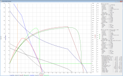
Increasing the battery voltage in series star mode, the situation betters:

Sim2.png

Switching to series star mode and adding one more 12V battery to obtain nominal 60V I have 336.6W/8km/h/14.5% versus 425.6W/8km/h/18.5%, I win 90W or 4% grade. As the grade threads in the graph show, between 4km/h and 12km/h the 60V/series star obtains 127% of power compared to the original configuration. Losing around 10W additional copper losses (not simulated) in switches and additional copper, I may end at 123% or 122% thinking of the weight of one more battery.

This is not what I dreamt, but still it may make my e-bike experience more pleasant. So I will buy some four capacitors to modify the controller (see above), hoping I won't destroy it. Also, the simulator says that the motor will make it for more than 2mins. Overheat in 200s (i.e. >150°C).

I also compared the original motor to

  • a serial delta version,
  • a serial delta version with 60v,
  • the original motor with 60v,
and found that the serial star with 60V is best.

I will report practical results hopefully soon. Any comments on the post above concerning controller-modification are highly welcome.
 
Thinking about my simulation results I came up with an idea how to compare apples with apples and not with pears.

If parallel to series switching increases motor resistance by 9, motor inductance by 9, motor induced voltage by 3, and this needs three times more voltage and three times less current, then let's test it. To compare these apples I increased battery voltage from 48V to 144V, reduced the battery Ah from 10Ah to 3.33Ah and reduced the 22A battery current limit of the controller to 7.33A. Not for real but in the simulator.

Here's the result:

View attachment 1

Click this link for a larger image: ParallelSeriesSimulation.png

Following this simulation result the motor used in series mode is obviously better than in the original parallel mode. More voltage and less current are better. This is not really astonishing as more voltage requires better isolation whilst more current means more losses in the MOSFETs.

This result also convinces me, that the picture "Qualitative torque ..." from the PhD Thesis of Eckart Nipp, which I posted above, is nonsense. I do now agree with esselius who wrote above: "Different windings won't give you another gearing".

Nonetheless, my plans are to use 72V and series mode, replace 4 capacitors, replace 9 FETs, and abolish switches and rigid copper in the axle. As further simulations have shown, this is significantly better at low speed and high grade than just increasing the current limit, which would destroy my batteries even faster than the current current limit of 22A was able to. More about this later.
 
I have now ordered 9 MOSFETs IRFB4110 (100V) as well as 100V-capacitors (the four capacitors mentioned above) to run the motor at 72V.

To make sure that the controller won't be damaged when using 72V batteries, I plan to keep all parts of the controller running at 48V, all parts but the MOSFETs, which will run at 72V. The 48V entry will be buffered by one of the old 470µF/63V capacitors.

Thus the low voltage detection will work as before.

Any possibly present high voltage detection will be fooled.

With voltage raised by a factor of 3/2, I will want the the battery current limit of 22A reduced to two thirds (14.67A) in normal operation. Following the simulator, this guarantees that losses at all speeds (up to 32km/h now) will be at least slightly lower than before. At speeds between 24km/h and 32km/h losses will be significantly lower.

When climbing this steep hill here, I will switch back to 22A battery current limit for two minutes, allowing for additional 140W of mechanical power at 8km/h compared to the current configuration. To realize this, I plan to use a LM358 dual operational amplifier:

220px-Operational_amplifier_noninverting.svg.png


This circuit will be inserted twice, once at pin 31 of the µController and at once pin 41 of the µController. Each of these pins measures a lowpass filtered version of the voltage at the shunt *. With equal resistors the original voltage will be measured. A third resistor can be switched parallel to Rf, to increase the measured voltage by a factor of 1.5. Thus the controller will reduce the battery current limit to 2/3 of the original value.

As the losses will be over 1000W when climbing, I plan to glue a 1N4148 Diode to the coils for temperature measurement and use a simplified version of a circuit I found at electroschematics.com.

After temperature measurements I may decide to adjust the current limit to more than 22A for hill climbing, allowing for even more than 1000W losses for 2 mins., while at the same time increasing the available mechanical power.


*) I still have to verify whether my controller indeed measures the voltage at the shunt at pins 31 and 41. I found this on the site of A van Dalen in his PDF.
 
I received the ordered 100V-MOSFETs and 100V-capacitors, and I hope to find time soon to replace the old parts of the controller and then test the motor first at nominal 60V then at nominal 72V using more 12V sealed lead acid batteries.

Following simulator results, climbing the 200m of estimated average 25% grade should then be much easier at 22A battery current limit. If this turns out to be true, I will remove the rigid copper in the axle as well as the switches and run the motor in series mode only. This has lower maximum speed but fits well to my habits and will increase range significantly, if the current limit is reduced to 2/3 in normal mode and then switched back to 22A in climbing mode.

The circuit for temperature measurement is nearly ready. I made it small enough to be integrated into an old $8-Multimeter.

If all works out fine, I plan to sooner or later exchange the now 6 pieces of 12V sealed lead acid batteries of ca. 2.5kg each, by lithium batteries, which will occupy part or all of the space of the original 4 pieces of 12V sealed lead acid batteries.
 
As a firm believer in the KISS principle I was nearly forced to bail on this thread. Before going further into what appears to be a time and money pit, I suggest checking your no-load current, because if no-load speed is 1/3 of original you didn't create a series/parallel switch. That would cut it in 1/2, so at 1/3 my concern is that it doesn't end up a proper winding for the hall sensor placement.

KISS would tell you the motor isn't the problem, the load is, so dump the lead batteries in favor of lithium. You'll love the difference in how the bike feels and performs. With pedal help that weight reduction may be enough to get you there.

Simply boosting current is an option too and could generate enough power that the motor doesn't totally bog down. As the cheapest option it's hard to ignore though you would have to watch the heat. At the end of the ride poor saggy lead batts may not be able to serve up the current you need without voltage plummeting to kill the benefit.

With a hill like that the best easy option will be to put a little geared hubbie in the front wheel. Then regardless of batteries or controller for the 9C, you'll have the billy goat climbing ability that you need. If that's out of your budget, then some kind of cheap helper motor that you can kick in just to help the 9C by a few hundred watts at 10kph or so would be a lot easier than the switching. Something along the lines of a Kepler friction drive would be a great helper with very little added weight.

A 9C doesn't have a thick enough axle to bring the wiring you need out of the motor, not without harming overall performance with a lot more resistance that's likely to create a failure than fix your climb issue.

That's my 2 centavos anyway.
 
John in CR said:
That's my 2 centavos anyway.
Thank you very much for your centavos! I will reply to your comments later. First I will report what I did today.

I modified the controller. I exchanged the 9 MOSFETs (originally P75NF75) by IRFB4110 (100V), and I exchanged the above mentioned four capacitors by 100V types. To make sure that all parts of the controller, but the three highside MOSFETs and the said four capacitors (and two more parallel small orange capacitors of probably 100nF), continue to run at 48V, I had to detach two wires and one more other part of the circuit. So now the controller's main battery + input is only connected to three of the MOSFETs and said 4+2 capacitors. All other wires and parts of the circuit which were connected to the main battery + input now have a separate input for 48V. I didn't have to add a new wire for the 48V input, I used the starter lock wire.

Thank God, all worked out fine. When removing the old MOSFETs I destroyed some of the conducting paths, but that was repairable.

I first tested the modification with 48V in the original parallel star mode. Idle rpm turned out as expected. As I have no tachometer, I just used a multimeter to measure the electrical frequency. At full idle speed the PWM duty cycle goes to 100%, so the multimeter returns the electrical rpm which are 840Hz at idle speed for my motor. (At less than full speed the multimeter shows the PWM frequency of 15-20kHz.)

Then I switched to serial star mode, and idle speed went down to a third as expected.

Then I put in the 5th SLA battery. 60V nominal for the MOSFETs and 48V else. Then I put in the 6th SLA battery. 72V nominal for the MOSFETs and 48V else. With 72V at serial star mode I measured electrical rpm at 420Hz as expected. To reach the same 840Hz as in original mode at 48V I would need now 144V but with 72V I only get half.

Next step was to remove the switches and remove the copper from the axle. I opened the motor again and hardwired the new serial star mode there. Now I have the original cable in the axle, which luckily turned out to still be long enough to reach to the controller. Tomorrow or else next week I will mount the whole thing to make a first road test.

I have to mention that the two 470µF/100V capacitors which are mounted standing on the board have the proper diameter to match the white printed circles on the board, but they are 1 or 2 mm to high to fit the box of the controller. Lifting them and bending them slightly to the side and using insulating tape solved the problem though. Maybe originally they would use only 330µF/100V capacitors instead in the 60V version of this controller. Or there are 470µF/80V capacitors which are small enough.

I left out that temperature measuring thing I mentioned above, because I had problems which to describe would be of no public interest. I will report on this topic if I will and can make something work. In the meantime I hope that my 2mins of high losses will be no problem.

Concerning the battery current limit I found out that on my board the microcontroller does not measure the shunt voltage at pin 31 and pin 41, but at pin 31 and pin 38 (IIRC). But at whatever pins the microcontroller measures the shunt voltage, there is one and only one path from the shunt to the controller, which can easily be cut to insert only one OpAmp which would make the microcontroller read a different voltage. I plan to care and then report about this topic later.
 
John in CR said:
As a firm believer in the KISS principle
What is the "KISS principle", please?

John in CR said:
I was nearly forced to bail on this thread. Before going further into what appears to be a time and money pit, I suggest checking your no-load current, because if no-load speed is 1/3 of original you didn't create a series/parallel switch. That would cut it in 1/2, so at 1/3 my concern is that it doesn't end up a proper winding for the hall sensor placement.
Correct me if I'm wrong, but my parallel/series switch switches originally nine parallel wires to three times three wires in series. If I had found two or four or eight parallel wires I might have been tempted to switch them such that the copper resistance and inductance would have increased by a factor of four and not nine.

John in CR said:
KISS would tell you the motor isn't the problem, the load is, so dump the lead batteries in favor of lithium. You'll love the difference in how the bike feels and performs. With pedal help that weight reduction may be enough to get you there.
The weight difference between SLA and Lithium is less than a factor of two. My SLAs make orginally 10kg, now 15kg, of a total of 100kg/105kg of weight. Simulations show that this is minor detail. It concerns the range well more than the capability to climb grade,

If my new system works, then I will sooner or later switch to Lithium, because with Lithium all the 72V batteries will fit into the originally destined place for the (so far 4x12V SLA) batteries. If I can make this 25% grade without major problems, I will be ready to spend money in the order of the total cost of the bike so far.

John in CR said:
Simply boosting current is an option too and could generate enough power that the motor doesn't totally bog down. As the cheapest option it's hard to ignore though you would have to watch the heat. At the end of the ride poor saggy lead batts may not be able to serve up the current you need without voltage plummeting to kill the benefit.
I will have to boost current each time at the end of every ride, each time at the end for two minutes. Now, with 6 instead of 4x12V SLA batteries I already increase total available energy for every ride to 150%. Also, I will use up less energy typically at like 24km/h. So I have better chances than before, to make that final 200m of high grade.

John in CR said:
With a hill like that the best easy option will be to put a little geared hubbie in the front wheel. Then regardless of batteries or controller for the 9C, you'll have the billy goat climbing ability that you need. If that's out of your budget, then some kind of cheap helper motor that you can kick in just to help the 9C by a few hundred watts at 10kph or so would be a lot easier than the switching. Something along the lines of a Kepler friction drive would be a great helper with very little added weight.
Yes, esselius above said "stokemonkey style or small wheel is the way to go." It is true what both of you say. But I will first try to solve my problem with the material I have plus some fifty bucks or so. Maybe it works. Maybe later I will be sorry and admit that I should have heard you right from the beginning.


John in CR said:
A 9C doesn't have a thick enough axle to bring the wiring you need out of the motor, not without harming overall performance with a lot more resistance that's likely to create a failure than fix your climb issue.
I removed that copper. I didn't do that because of the electrical losses. They were like 2%. No problem. I did it because of the high risk caused by poor mechanical safety of the insulation.


John in CR said:
That's my 2 centavos anyway.
Thank you very much! It is most important to think of all aspects, and for a Newbie like me it is good to hear comments of experienced folks.
 
Ok, I got it now. A brain cramp got the better of me, and due to the strand count you had to split each phase into 3 for triple the turns on each tooth when you put them all in series compared to stock all in parallel.

My point about too much copper to bring out of the axle applies if your switching is done outside of the motor. If the switches are inside then it's not an issue.

I live in a mountainous country and where I lived when I first got into ebike had a 25% uphill grade leaving my house though less than 100m and another of 20% that was on a road I was forced to use about half the time. My bike couldn't handle either in original form, and I had to zig zag up them which flattened the grade enough to get up. The solution was simple...increase controller current. The longer 20% grade had a speed bump just before the hill started, and the increased current helped me accelerate more quickly, so I had more speed as I hit the meat of the hill, and combined with the extra power of the higher current, I crested the top only slowed down to about 15kph with no pedal assist. Before it bogged down to near zero even with maximum effort, and it heated the windings up so much that the increased resistance made a significant performance decrease that faded within a couple hundred meters of going easy on the flat area at the top as the heat moved to the stator steel. The steep section leaving the house still required full pedal effort, but going straight up it was short and quick enough that the motor didn't suffer from too much heat building up since it was a cold start.

While the extra weight of the lead batts doesn't require all that much work to carry them up the hill, you were living right at the edge of being able to make it up, so they may have been the straw that broke the camel's back. Once you dump the lead you'll wonder why you waited so long, because the effect of that weight on the "feel" of the bike is significant. That's not the biggest negative they have on your climb. The voltage sagging like grandma's titties is what killed you, especially since it was even more pronounced since it was at the end of the ride.

Here's the scenario your motor is already at a healthy operating temperature with your saggy lead batteries running low, and you come to the killer hill and ask your system to deliver full power by going to full throttle approaching the hill. Voltage sags more than at the beginning of the ride, so you carry less speed going into the hill. You don't have enough current and voltage to create enough power to maintain speed, so as you slow to a crawl efficiency of the motor plummets on it's way to near zero. The continued current draw make voltage sag even more for less power, and the windings start heating up for even less power. While our legs are good at making torque your crank rpms are dropping too, so your human power input is plummeting too. While it would only take 400-500W to climb the hill at just 5kph, the motor wasn't even able to deliver half of that for the reasons above, and the effort exhausted you.

Because the climb was right at the limit of going into a stall, I have little doubt that just better batteries would have had you zipping right up at 10kph+ with comfortable pedal assist, since it would have taken half as long. A 5-10A increase in current in addition to better batteries and it's few less kg of load would have surely done the trick.

It seems like you had fun figuring out and doing all those changes. Yes the lower Kv helps climb hills, but more slowly, and it's benefit is really more applicable to continuous climbs, and much less so for a relatively short steep climb. Power is what you need to maintain speed on the hill, not just torque, and power is where the slower wind falls apart without proportionately changing voltage, but changing voltage proportionately puts you right back to square one except that you're taking an efficiency hit in the wiring.

If you really want to make a change for the better other than better batts and a touch more current, then decrease the wheel size. Then increase the voltage by the same proportion for the same top speed, and you've got both more power and more torque, and you're a happy camper. That's another KISS solution.
 
Thank you again for your comment, John. I think you're right on all topics as my report of today will show.

Today I reassembled the bike and tested it on the road. The two additional 12V SLA batteries were mounted on the rack behind the saddle. Maximum speed now is estimated 24km/h, half of original full speed. That's fine, my typical cruising speed now is maximum speed which means that I have high efficiency in typical operation.

First I tried climbing the last 20m of altitude difference (of a total of 50m) up to my house. The first part of this stretch is less than 20% grade, the last part more like 30%. I made this stretch significanly faster than before, but I still had to stand up for the last section. My impression was: The motor now has more power, but this does less serve to significantly relieve me and more to climb faster.

A tour of several kilometers showed that there are drawbacks. Trying to make it past the traffic lights in time is not as easy as it was. Also, when attacked by some bulldogs my escape speed was comparatively low. Luckily they still didn't get my legs for supper.

Checking the outside motor temperature every once in a while, it didn't exceed estimated 40°C.

When returning home, climbing the 50m/200m grade, the motor stopped to provide power after a few meters. It didn't even want to carry the bike alone with me walking along. I went down again and found out that the reason was one of the batteries. Beside the four 10Ah SLA I normally use, I added one more of the same type (which previously was installed in my computer's UPS) and another one, which is one of those 9Ah, which were originally shipped with the bike, and which look somwhat misshaped, having lived some stress. That latter one was considerably warmer than the five others. When riding with only the 5 good ones (60V) the problem disappeared.

My next step will be decreasing the battery current limit for normal operation to 2/3 of the given 22A, and inreasing the battery current limit for climbing to 25A or 30A or whatever amperes are few enough to not fry my fingers when touching the motor.

But what is a battery current limit of 25A or 30A if you have 10Ah SLAs? I have knocked the stuffing out of 9Ah SLAs at a 22A limit within a few months. I will need batteries which can be discharged at 4C or something.
 
Ok John in CR, the simulator says that the slow series star is slightly better than the fast parallel star winding, if the voltage is increased. Furthermore you say that I have to increase current and that I'd better decrease weight. I am like 60kg. The bike is 40kg. I won't drink less beer so the SLA batteries would have to be replaced by less kg per Ah.

I read a huge number of articles posted in this vast forum today. And I have learnt, that it is much more difficult and more expensive to build battery packs than I thought. Spending R$1000 (US$454) on batteries would not be enough, much more work and/or money would be involved.

- Battery management might be necessary. Trying to avoid it, involves additional costs on better batteries.
- Conventional soldering is risky. Besides additional costs for damages it might destroy the idea to omit battery management.
- Battery management for 20s6p or similar of power tools 18650 in my eyes seems very complicated and in praxis rather hard to monitor.
- Spot welders are expensive.
- Building a home made spot welder starts at US$200 and ends depending on how many semiconductors get lost in the process.
- Buying a 72V >=10Ah manufactured solution fitting my geometrical needs costs more like US$1000 or rather upwards when thinking of 60% taxes on import.

I don't have a car. My wife and I spend less on taxi (cab) rides than taxes/insurance/gasoline for even a small cheap car would be.

So, before entering new territory with batteries which are less heavy and/or less big, but much more complicated to handle and at least four times more expensive, I decided to use one more 12V SLA battery to fill up my well working set of 60V to 72V. The manufacturer is CSB from Taiwan. The type of battery is HRL 1234W F2FR (datasheet). These batteries cost me R$50 (US$23) plus shipping from a neighbour state here in Brazil. I will order more three of these, as I will need one for my computer's UPS, and a spare one, which I will parallel to the computer's UPS.

Then I will increase the current limit from 22A to something like 30A, by "amplifying" the voltage which the µC reads at the shunt by a factor < 1. The idea is, that the comparatively cheap SLA batteries will survive this for two years or more. If they do that, the decision was good, if they die prematurely within months, the wrong decision cost me R$50 (US$23).

Motor temperature did not seem to be any problem in my tests so far. So my questions now reduce to

  • what current will these SLA batteries deliver without losing too much of life span
  • how much current do I need to make my grade with an amount of assistance I can render even after one or two or three or four beers

Then later, when I wrecked more batteries, hopefully later than sooner, then I will think about Lithium or whatever then will be state of the art.
 
Since you didn't have heat problems before, which to me was obvious with the pristine windings on a motor that's been repeatedly bogged down on a hill to near zero, then you had untapped torque potential, and all you had to do was increase current. The beautiful part of it would have been that increasing power and performance with a simple and cheap increase in current would have decreased the energy required to make the climb, so heat would still not be a problem and you wouldn't be exhausted at the top because your pedal effort would have been shorter and easier. I didn't mean the list as do all of those things. It was a list of the simpler things that would have worked.

BTW, 12ah lead batteries aren't really 12ah of capacity. If you want the lead to last, then due to the Peukert Effect combined with not discharging past 80% of capacity to avoid premature death, you're left with not much more than 6ah of usable capacity. That means 8ah of lithium is a more than fair comparison in terms of capacity. If your budget is extremely tight then the way to go lithium is by recycling used packs, because a single bad cell or connection between cells can render a whole pack useless for it's designed use. You might even be able to source what you need for free. If you lived near me, we could have bartered your expertise and less time than you put into the series/parallel switching in exchange for free batteries and solar charging as a bonus. You have the lead already, so once you're up and running go visit a recycler in your area to see what's available. They often have piles of lithium packs set aside because they don't know what to do with them. If they do, go for cordless powertool packs first, because they contain high power batteries.

In the meantime, I hope your plan works out, but be leery of a simulation that's telling you you're better off than before, since it's the same motor less some copper losses you introduced, and it wasn't wound to such a high Kv that your load was too big to zip right up in its original form. The current limit was simply too low to generate the torque required.
 
I read some postings of some compatriots at rc-network.de. They tear the spot welded nickel strips off their Sony Konion US18650V3 and replace them by soldered copper strips using a 100W 450°C soldering iron. Neither mechanical nor electrical properties of the spot welded nickel strips convince them. So if they can do it, I can do it. I found a video too (in German language), soldering of 10s4p Konion.

Soldering batteries looks like a solution which is feasible for me, not too big a challenge, not too time-consuming. Also, I prefer to avoid a battery management system, which is one more device with many parts that can fail.

I'll have to buy a new charger for 72V anyway. At the moment I charge the additional batteries using an old not-so-high-precision adjustable power supply. Voltage limit setting seems quite stable though.

Thanks John, for pointing out the comparison of lead Ah and lithium Ah. In fact, my lead batteries nominally are not 12Ah but 10Ah. My mistake, typing the wrong number above. So using 20s4p of US18650V3 2250mAh would already be more actual capacity than my sealed lead acids now have, beside well more rated discharge current. Numbers on alibaba.com tell that this might be around US$300 (plus 60% for the robbers at the customs, if I don't get lucky). Hopefully I can find names of trustworthy chinese suppliers here on the forum or elsewhere.

The available space designated for four SLA batteries (each 151mm x 91mm x 65mm) could be filled with 135 pieces of 18650 (not even packed like a honeycomb). So up to 20s6p would match.

John in CR said:
In the meantime, I hope your plan works out, but be leery of a simulation that's telling you you're better off than before, since it's the same motor less some copper losses you introduced, and it wasn't wound to such a high Kv that your load was too big to zip right up in its original form. The current limit was simply too low to generate the torque required.
The additional copper and the switches have already been removed. The copper now is only the motor's original copper. So the copper losses in the motor are equal at equal electrical power entering the motor. The phase wires I use now are the original phase wires less some few centimetres which got cut off during the two conversions.

The simulations say that there is only a slight difference between climbing with the serial star circuit and climbing with the original parallel star circuit at the same electrical power input. I agree, don't trust a simulation without corresponding experiments. I thought about verifying whether this simulation result is true when the switches still were there, but I guess that that would have required a good torque measurement setup.

The main reason why I decided to stay with the serial star is because it will increase range significantly, considering my riding habits. The motor will be operating at near full speed, where no battery current limiting occurs and efficiency is high, most of the time. With the original configuration I was going most of the time at near half maximum speed, where battery current is limited and efficiency is comparatively low. With the original configuration and 72V I would be going at near a third of maximum speed with efficiency still lower. So the serial star should serve better for my purpose, whether or not in reality it additionally helps a little bit when climbing.

Concerning the switching of the current limit for climbing versus normal operation, I plan to implement that soon, even with now only 60V available, not waiting months for the arrival of new batteries from China. I'd like to see the effect of increasing the amps rather sooner.

I had thought of using used lithium batteries before. But it seems that it is not easy to get them here in Brazil, at least not for an acceptable price, and rather improbable to get types which allow for omission of battery management. So I discarded that, assuming also that aquisition, selection, and cure, as well as later maintenance probably would take a rather big amount of time.
 
I have plenty of Konion packs, but ripping off the existing tab welds is no way to build a pack and results in 10X the work and a more problem prone pack. Plus you give up the great cell matching and proven tab weld connections, which actually makes slightly used cells better than new ones. Those packs generally have one bad parallel pair. The easy way is to rip those out leaving the tab intact with the good cells. Check the remaining blocks of good cells for balance, and if they're balanced, then they're well matched.

Next is to capacity test the cell blocks. I wait until I have large amounts so I can comparatively test them quite easily and then mark each with my own grade, A-B-C etc. The test is simple, but care is required due to the very high voltage. First I get all the blocks to the same cell voltage, by charging same series count blocks to the same voltage and leaving them in parallel for a day or more. Once I have all blocks to a conservative 4.15V per cell, then I string them together in a single long series string. The for my discharge resistor I use incandescent 100W lightbulbs in series, 1 for approximately each 100V of string voltage. I've had to use as many as 9 in series. I keep the light string well away from the battery string due to the heat, when I first connect I note the time and measure discharge current, approx 1A, to give me an idea of roughly how long to let it run to discharge approximately 2/3rds of the nominal capacity. I check cell voltage occasionally during the process and interrupt the discharge when it hits nominal voltage of 3.7V for most of the cells. The best cells have higher voltage. I measure current then for a rough average current so far and note the time. I consider that the ah discharged so far (avg current over time) to be half of operating capacity of the good cells, which compared to nominal capacity gives me an idea of general cell health. If any of the blocks are already running low, I remove them and grade them F. I start the discharge again and run it until the highest cell voltages are about 3.5V . Then I break the string down to blocks and mark the voltage on each. Then I sort them by cell voltage and check each pack for balance. Highest voltages with good balance get an A, and next group a B, etc. Any blocks that have balance except for one pair get graded according to the voltage of the good ones and I mark an X on the low pair(s) for removal from the block.

Then get good blocks I want to use charged back up to identical cell voltages, and build my series strings of same grade blocks with just a few tab on tab solder connections. Konions self balance to some extent if you don't discharge them too deeply, so most of my packs are simply separate strings paralleled at the ends. Once I gained confidence in strings staying balanced, I never worried about making parallel connections or checking balance. I'd just add a 12ga positive and negative lead to each end of each string and wrap it in one layer of the world's best ebike battery material, duct tape, for some water resistance and a bit of structural rigidity. Then I took 2 or 3 strings and put a strip of thin closed cell foam between them and duct taped those together for a 4p or 6p string for combining into packs.

I've made about 50 of those 2p strings for a variety of packs, most in service since 2008 and 2009, with only 2 failures. One was the only pack I did parallel connections, and one cell must have gotten too much heat during soldering and the plastic melted enough to short at the button end and kill all 10 parallel cells. The other was a 3 year old pack with nearly daily use, and I noticed some softness in the top of charge voltage and some added voltage sag. All but one of the parallel strings were healthy and balanced, but one string had a bad cell pair whose heat weakened the 2 adjacent cell pairs. That's a big advantage of long strings (I use 20s), one bad pair doesn't put the other cells into cell destroying high voltage if you use a conservative top of charge voltage, but if you pay attention they give hints that something is wrong.

All my konion packs are on bikes of others now that I moved on and need much higher power batteries. I do miss the convenience of my konion packs though...Just ride, connect the bulk charger upon return, and disconnect it sometime later, and never worrying about balancing or even checking for balance, and no need for the cost or hundreds of additional potential points of failure...the ultimate in battery convenience.

Seriously don't go pulling the tabs off of Konions. Pulling them off can damage a cell, as can each solder or weld connection you make. Robotic machines did the work for you, and usage proved the remaining good cells have good connections, and you want to disturb that factory made block as little as possible.
 
What is it that you believe changing current limits to something lower during normal riding will accomplish. As long as you ride the same top speed It will have only negligible effect on efficiency, because it requires the same amount of work to accelerate to a given speed. Yes you use higher power to accelerate quicker, but it is shorter in duration. The difference only comes about because accelerating more quickly puts you a cruising speed for longer and therefore a higher average speed, which gives more back to the wind. As long as aren't pushing the motor into saturation at the higher current, then you aren't creating more heat. As long as you're not talking about extreme acceleration, being able to get up to cruise more quickly is safer and more fun. Once you set your bike up to climb that hill without heat problems, you're good to go for all riding. Zippy acceleration at no cost is one of the great things about electrics. :mrgreen:
 
Thank you, John, for your extensive report on your experience with Konion cells. Full of valuable and useful details and tips which I think will not only help me but hopefully many others. I don't plan to rip off spot welded nickel strips, I was just glad my compatriots did it, not on used cell packs, but on new cell packs. They showed me that I don't need to build a spot welding devil's machine to build a battery pack. They explicitly recommend soldering Konions while at the same time explaining that manufacturers don't recommend that and also warning that some soldering practice is needed to not damage the cells. I play piano and guitar and more instruments including diverse soldering irons and blowtorches, so I feel myself ready to copy their doings. I assume I will have to deal with new single cells without soldering tags. If I could get cells with soldering tags, I might prefer these. Ripping off existing tags may damage a cell, as you warn.

Concerning your use of incandescent 100W lightbulbs as a load resistor. That's KISS. A while ago I thought of using halogen lamps as a load resistor of around 1Ω to be able to manufacture a homemade fairly good precision mΩ Shunt from 1mm iron wire. But then I found that some few meters of the same iron wire wound around a PVC tube of 100mm diameter does serve the purpose too. I used this load resistor to measure the actual 7-8mΩ of the switches I used for parallel/series switching.


John in CR said:
What is it that you believe changing current limits to something lower during normal riding will accomplish. As long as you ride the same top speed It will have only negligible effect on efficiency, because it requires the same amount of work to accelerate to a given speed. Yes you use higher power to accelerate quicker, but it is shorter in duration. The difference only comes about because accelerating more quickly puts you a cruising speed for longer and therefore a higher average speed, which gives more back to the wind. As long as aren't pushing the motor into saturation at the higher current, then you aren't creating more heat. As long as you're not talking about extreme acceleration, being able to get up to cruise more quickly is safer and more fun. Once you set your bike up to climb that hill without heat problems, you're good to go for all riding. Zippy acceleration at no cost is one of the great things about electrics. :mrgreen:
You focus on the process of acceleration from 0 to some cruising speed. I would have to think about whether shorter higher acceleration is more or less efficient than longer lower acceleration. My idea is a different one. Mostly I go at some constant 20-25km/h. I don't use the motor as long as the road is rather flat or downhill and there is no contrary wind. After descending the 50m height difference from my house, I mostly ride along sea level (the house is at 50m only for the the purpose of panorama.) When the motor assists, it typically assists for some minutes against a rather slight grade or a more or less minor contrary wind. But then it assists at a speed of typically constant 20-25km/h. That's because 20-25km/h is what I can comfortably ride on this given bike without motor and without much effort as long as there are no more adversities than the higher weight compared to a normal bike without additional weight of motor, batteries, etc. A motor with windings appropriate for a top speed of 50km/h will then be less efficient than a motor with windings appropriate for a top speed of 25km/h, because the highest efficiency of a motor is quite close to maximum (idle) speed.
 
Back
Top