Mystery controller help needed.

teejmeister

100 µW
Joined
Jul 29, 2014
Messages
9
Location
Norfolk
I am building my first ebike.
I bought a kit second hand off eBay.

I have:
Motor: 48V 1000W (has "marketing@senyuan-motor.com" cast into inside of side cover.)
Controller: 48V 1000W (only has 48v1000 written on it in pencil)
Battery: 48V 15Ah LiFePo4 (wrapped in duct tape type)

I found this picture online showing an almost identical controller.
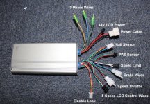
controller.JPG

I tried connecting the motor to the 3-phase wires colour to colour.
The Hall sensor plug matched the one on the motor and the colours matched up, so I connected those.
I connected the twist grip throttle to the Speed Throttle wires, colour to colour.
I connected the Electric Lock wires together.

I saw a big spark when attaching the battery, I hope this was just the capacitors in the controller charging up, but saw no movement from the motor.

I have seen places selling controllers with the 5-Speed LCD Control Wires warning that the controller will not work without the LCD part!

I would appreciate any advice on what to do next to get this setup working.
Thanks in advance, Teej :)
 
Most controllers can run without the LCD. You need to jumper wires 1-2 and 3-5. If you can show a closeup of that connector I can tell you the colors that are usually used.
otherDoc
edit: Your LCD connector appears different than mine. Do provide a closeup, please.
edit2: Hmm......I just saw your statement that the controller in the picture is "almost identical". How close is it?
 
Thanks for the reply.

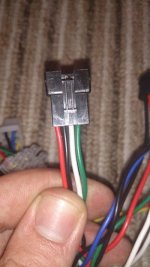
Looking at it again it seems to be a 3-speed controller, as it only has 4 wires.
speed.JPG
Do any of these need to be bridged to get the controller to work?

It now looks like the BMS is not working properly.
The battery voltage is reading 51V and the output of the BMS 50V, but when I connect the controller and join the "electric lock" wires the voltage from the BMS drops very quickly to 1.5V and when the lock wires are disconnected it climbs very slowly back to 50V. So it looks to me like the BMS is not supplying any current.

Any advice on what to try next would be much appreciated.

Thanks, Teej :)
 
I would start by troubleshooting the battery first. Put it on charge and read the voltages at the BMS connector for each cell. That will tell a lot. Be careful and don't cross your probes from the meter. Write the voltages down and some of our experts can jump in and help. I hope you didn't pay a lot for a used battery?
otherDoc
 
Four wires to the display means it's for a LED unit, not a LCD used with a sine wave controller.
They would be the LED800\860 series among other names.
I think they are available on Ebay for cheap.
 
yes, battery first. post up a picture of the battery showing the connections and a picture of the BMS too. can you measure the current flowing into the battery when it charges?
 
Thanks again for the advice.

I have done as you said, and these are the readings I got:
b1=3.3
b2=6.7
b3=10
b4=13.5
b5=16.9
b6=19.8
b7=23.1
b8=26.3
b9=29.7
b10=33
b11=36.5
b12=39.8
b13=43.1
b14=47
b15=50.4
b+=53.7

The battery was not exactly cheap, I did take a bit of a gamble on it. It does look unused though and I did not fancy waiting for one to be shipped from China.
Teej
 
A model number for the kit, the controller, anything can help.

13.jpg
 
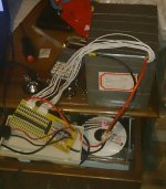
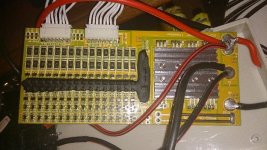
Here are some pictures of the battery and BMS
Battery.jpeg
BMS.jpeg

I have no info at all on the controller other than it looks identical to the one I posted earlier.
 
I don't have a DC ammeter handy, I will try to get one tomorrow.
docnjoj said:
edit2: Hmm......I just saw your statement that the controller in the picture is "almost identical". How close is it?
All the wires seem to match in colour and grouping, my controller has different plugs on some of the wires, white instead of black.
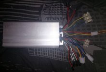
The extruded case looks identical but is fitted the other way around with 6 groves at the bottom, and the "Electric Lock" wires exit through the same gland as the battery and phase wires. Here is a picture of it.
MyController.jpeg

Would the unbalanced battery stop the BMS delivering current?
How would I go about rebalancing the battery pack?
Would the out of balance cell be due to cell failure, or is it a matter of getting all the cell voltages equal again by discharging the high ones?

Thanks again for all the help,
Teej :D
 
There appear to be six wires to the LED, not 4. There's another 48v connector with two wires.

The LCDs normally have 5 wires, but yours has a two grounds for whatever reason. The 5 wires are:
48v to the LCD
48v back to the controller when LCD is switched on
Transmit data (Tx)
Receive data (Rx)
Ground.

You can confirm which wire is which by opening the controller. The 48v wire going to the display will be connected directly to the thick battery red wire, so is often positioned next to it. The 48v wire coming back from the LCD, which powers the controller, will go to the big resistor/s so will be positioned near to one end of it/them. Those two wires have to be shorted to power-up the controller.

It looks to me like the 2-pin connector carries the 48v to your LCD (which you don't have), the red on the 5-pin carries it back, the white and green wires on the 5-pin are Tx and Rx, and you have a common ground on each connector. Therefore, you need to short the two red wires. I think I would check their positions on the PCB first just to make sure.

You can check whether your controller is powered up by checking between the red and black throttle wires, which should be 5v. If no 5v, the controller is not powered.

Note: The thick battery wire connected to the controller does not actually power it even though you got a spark when you connected. That wire goes directly to the FETs, which block it until the controller's CPU is powered, and the spark is from the main capacitor, which is across the positive and negative.
 
you made this comment about how you did not buy the battery from china. did you buy it from someone local and can take it back and get your money back?

the battery is unbalanced. it will not charge because channel 14 is already overcharged. it appears you are hitting LVC on channel 6 when it tries to deliver power since channel 6 is uncharged essentially. 3.2V while charging is uncharged imo.

it is too bad that there is this constant racial hysteria here on the ES about how batteries from china are cheap fostered by the jason guy who sells batteries for the all_cell people. i suspect you are a victim of that hysteria. unknown manufacturer. unknown pack.

the controller problem is trivial compared to not having a decent battery.

the chinese do make good batteries in spite of his comments. the only manufacturer we had issues with was Vpower and they have now changed their design and build procedures to increase the reliability to an acceptable level.
 
I think my comment on getting a battery from China was not very clear, I will try to explain the situation better.
I bought this kit on an eBay auction for slightly more than half what a new kit would cost and I have no warranty, so I am stuck with this battery.
I am quite sure the battery is from China and it is possibly a Vpower one, as it came with a Vpower charger. I was originally going to order a kit from China when I saw this lot listed on eBay, I took a chance on it because it was cheaper and I could avoid the long shipping time getting the parts from China. In hindsight it might have been wiser to order new parts from China and just be patient.

Can I rebalance the battery by tacking it apart, separating the cells and discharging the hi cells and charging the low ones until they are all equal, then put it back together?
 
In theory you don't need to dismantle the battery to balance it; however, that cell 14 doesn't look right at all. You should re-measure it just to check. I think it would be a good idea peel off the tape and have a look at that cell group. You often see one of the corner cells squished because the weight is relatively high and there's no protection.
 
ok, that yellow color does ring a bell. that is the Vpower BMS. first thing would be to expose the pack and see if you can see damage to the cans and then do some preventative work to reduce the chances of it shorting out on the nickel strap. it may be the newer pack though.
 
Hi all,

I have finally got back to this project.

I have unwrapped the battery and found some loose connecting strips on cell 14. I have got the pack almost balanced by discharging the high cells with a light bulb and charging the low ones.

I have connected the battery, controller and motor again. Now when I join the "electric lock" wires together I hear a click from the motor and I then have 5V on the throttle wires.
I have not managed to get the motor to move at all, turning the throttle has no effect.

Any suggestions on what I could try next?

I still think it may have something to do with the "LCD" wires. There are four wires on the plug, red, black, white, green. The red is 53V and the black is ground, now I am guessing that the white and green are Rx and Tx, does that sound right? I was wondering if the controller needs some sort of run signal from the LCD?

d8veh said:
It looks to me like the 2-pin connector carries the 48v to your LCD (which you don't have), the red on the 5-pin carries it back, the white and green wires on the 5-pin are Tx and Rx, and you have a common ground on each connector. Therefore, you need to short the two red wires.
d8veh, both the red wires on the five pin and the 2 pin are battery voltage (53V atm).

Thanks again for all the help,
Teej :D
 
Did you read everything in post #12?
Have you got 5v?
Did you check which wire goes to the big resistor?

The LCD contains the switch to switch the controller on. Without it you have to make the connection yourself. One wire goes from the battery to the LCD, and one carries the battery back to the controller to power it. It will not work unless you identify these two wires. You have to open the controller to find which one it is that comes back. The red one in the LCD connector is the one that carries the battery voltage to it. The other one must be the white or green. You can't try them because if you get the wrong one, it'll blow the controller beyond repair, so don't try and guess.
 
Yes I did read post #12, and I have 5V on the throttle wires.

I have not opened the controller yet to check which wire goes where, I will do that a bit later, and see where the white and green are going.
 
If you have 5v on the throttle, the controller is switched on, in which case you don't need to worry about the wires I mentioned before.

I just re-read everything. The picture you show at the beginning is of a Conhismotor controller. I have one of those. I just connected everything up and everything worked first time. Somebody else on the UK forum bought the same one and couldn't get it to work, so he sent it to me for testing. I swapped it for my one and it still didn't work. Everything seemed to be in order - LCD was on and showed good battery charge, throttle had 5v, etc, but it wouldn't give power (tested with a ebike tester), so I suggested he contact Conhismotor. They immediately sent him a replacement, but that one wouldn't work either. He gave up after that. I hope yours isn't the same. You said that the Conhismotor is nearly identical to yours. What's the difference?
 
Just turn the throttle a little to see if the motor will spin no need to full throttle if not turning, may cause damage. The phase and halls might not be a color match to work. Is the battery keeping balance ? This come from a private party ?
 
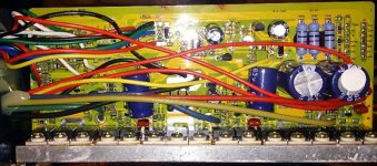
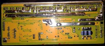
I have opened up the controller again and here are some pictures of inside.
DSC_0168.JPG

DSC_0167.JPG

These are the only external differences.
teejmeister said:
All the wires seem to match in colour and grouping, my controller has different plugs on some of the wires, white instead of black.
The extruded case looks identical but is fitted the other way around with 6 groves at the bottom, and the "Electric Lock" wires exit through the same gland as the battery and phase wires. Here is a picture of it.

I am beginning to think there is something wrong with the controller, though I haven't tried connecting the hall and phase wires in other combinations. I have not seen any voltage on the phase wires.
 
Back
Top