opperpanter
100 W
Hi all,
I was hoping you could me identify my *Bafang?) 36V250W ebike-kit so I can find out how to upgrade it to 48V.
Or maybe it already supports 48V.
Some photo's:
Motor:


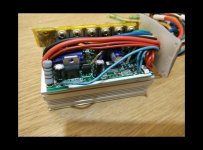
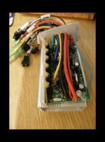
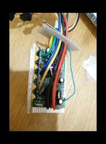
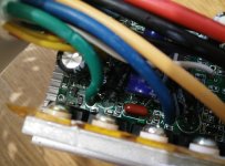
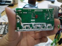
New controller:


View attachment 5

As you can see, there's no obvious known branding anywhere.
The guy has some contacts in China and managed to get his own brand on it.
I guess it's just a Bafang front hub motor? I got it in The Netherlands (where I live).
It's a 245RPM motor.
Rated power is 250W. The battery is a 36V11Ah LifePo4 (Pouch cells).
Controller max A is 12A, so motor is possibly a 350W? Maybe 500W?
The goal is to run it at 48Vs instead of 36Vs.
The reason is that my other bike will become 48V kit (BBS02 48V750W).
With a big battery pack. I want to share this pack with the bike above for more range.
I can get rid of the 36V11Ah (bulky/heavy) battery")
Question: can this motor run at 48V and 8A? That would be similar to 36V12A ?
Question 2: can this controller handle this?
You'll see two controllers in the pictures. The first is an old one. The newer is an enhanced version of the same controller, supporting better top speed (20mph).
My supplier says both engine and controller can't handle this.
For the motor I don't believe him. The controller I don't know.
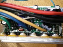
I can get better pictures of the controller if needed, maybe open it up?
The supplier doesn't want to tell me what exact engine/controller it is.
He doesn't want me playing around with it because of the warranty.
Plan:
Plan would be to buy a new controller that support 48V (and maybe 36V at the same time?).
I have been googling, but I haven't found a controller that matches the display.
The display has 9 speed settings and display Volts, Amps. Seperate +/- control and seperate thumb throttle.
This china supplier looks to have similar looking display, but no similar spec controllers.
http://www.fdm-ebike.com/Electric-Bicycle-Kit-LCD-Display-with-Computer-Bluetooth-p74355317.html
Thanks for any help,
Opper
I was hoping you could me identify my *Bafang?) 36V250W ebike-kit so I can find out how to upgrade it to 48V.
Or maybe it already supports 48V.
Some photo's:
Motor:
New controller:
View attachment 5
As you can see, there's no obvious known branding anywhere.
The guy has some contacts in China and managed to get his own brand on it.
I guess it's just a Bafang front hub motor? I got it in The Netherlands (where I live).
It's a 245RPM motor.
Rated power is 250W. The battery is a 36V11Ah LifePo4 (Pouch cells).
Controller max A is 12A, so motor is possibly a 350W? Maybe 500W?
The goal is to run it at 48Vs instead of 36Vs.
The reason is that my other bike will become 48V kit (BBS02 48V750W).
With a big battery pack. I want to share this pack with the bike above for more range.
I can get rid of the 36V11Ah (bulky/heavy) battery
Question: can this motor run at 48V and 8A? That would be similar to 36V12A ?
Question 2: can this controller handle this?
You'll see two controllers in the pictures. The first is an old one. The newer is an enhanced version of the same controller, supporting better top speed (20mph).
My supplier says both engine and controller can't handle this.
For the motor I don't believe him. The controller I don't know.
I can get better pictures of the controller if needed, maybe open it up?
The supplier doesn't want to tell me what exact engine/controller it is.
He doesn't want me playing around with it because of the warranty.
Plan:
Plan would be to buy a new controller that support 48V (and maybe 36V at the same time?).
I have been googling, but I haven't found a controller that matches the display.
The display has 9 speed settings and display Volts, Amps. Seperate +/- control and seperate thumb throttle.
This china supplier looks to have similar looking display, but no similar spec controllers.
http://www.fdm-ebike.com/Electric-Bicycle-Kit-LCD-Display-with-Computer-Bluetooth-p74355317.html
Thanks for any help,
Opper