help troubleshooting first ebike build

encinitas

10 mW
Joined
May 19, 2014
Messages
28
Location
Encinitas, CA
A small plea for help:

I excitedly assembled my first ebike kit yesterday, a bmsbattery Q11 48V 1kw kit, and attached the battery-- a calibike 48V 15Ah battery-- and whalah! Nothing. No power, no sound, nothing when I gave a little twist on the throttle.

I'd appreciate any suggestions for figuring out what's wrong. I'm no engineer, and struggle with deeper twists of the electrical conversations I read here, but can muddle through with some assistance.

There were no instructions with the kit or the battery, but all the connectors seemed to work themselves out--each one was different. I did have to splice different connectors onto the controller to match the ones one the battery. I charged the battery overnight, checked the voltage, and checked the connections again. Still, nothing.

I did see the thread with a user having problems with this battery, but am unsure if that is something I need to consider, and besides, there was no resolution on the thread. I also have not yet bought a display, so perhaps I am unable to set the controller properly? Also unsure what the little switch on the battery controls, because current doesn't vary when you flip the switch.

Both battery and kit seem to be well known on the forum, but here are their links, below. Thanks for any and all suggestions.

https://bmsbattery.com/ebike-kit/529-q11-48v1kw-rear-driving-e-bike-conversion-kit-ebike-kit.html

http://calibike.com/?product=electric-bicycle-ebike-48v-15ah-lithium-li-ion-battery-and-charger
 
First thing would be to double check all your connections.

The link you posted shows a kit that includes a pedal assist sensor. Are you using that? If you are then the cranks will need to be turning before the motor will kick in. I've never used a kit with a PAS and a throttle, but if the PAS is enabled, I am pretty sure the cranks will need to be turning for the motor to turn with power.

Have you checked the voltage of the battery?

Since you had to switch the connectors on the battery to match the controller, did you make sure you had the polarity correct with the new connectors?
 
Stud and D8veh,

Yes, checked the voltage: 50.5V

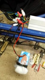
When changing connectors, I added wire (connectors came with controller) and kept red to red, black to black. See picture.

I did not hook up the PAS sensor yet. Just trying to get it up and running with throttle.

Re orange ignition wire, battery has large orange/red and black wires, connected them to the corresponding wires on controller, again, see picture. It also has a a small switch that, when toggled, the voltage jumps to 54.5V. And it has a connector for the charger.

I assume that fat orange wire is what you are calling ignition?

Now when I connect the big red and black wires and measure V, I get 2-3. I figured, when the throttle is applied, voltage should jump, but it doesn't. Again, I have little electronics knowledge, so that is only an assumption.

I think I attached the photo ...
 
you should not use wire nuts on major conductors. solder them together. why is the voltage so low on your battery? should charge to 54.6V. why is the end of the battery wrapped in foam and what is the other stuff hanging off of it?

you may not be able to make the controller work on throttle only if it requires pedelec, but i do not know these controllers.
 
And the red button on the throttle has to be in the out position if it's like my kit. And make sure neither ebrake lever is pulled even a little. Might be best to disconnect their wires until you get it running.
 
And who the hell talked you into getting that bmsbattery 48v 1000w kit when you could have gotten one locally cheaper and faster with free shipping?
 
Normally the controller's battery connector has three wires: thick black, thick red and thin red (could be orange). The thin red is the ignition wire, which powers the controller. It has to be connected to a battery positive - normally through a switch.

Be careful not to connect any of the other reds to your battery. They're all 5v, and if you connect them to the battery, you'll wipe out the controller. Was the controller supplied with a three-way battery connector? I see you've cut off whatever was there.
 
Just had another thought. They changed the smaller controllers to take an LED control panel. Does yours have the four-way connector for one? If so, the ignition wire is on it, in which case you have to join the red to the blue. On that connector.

It might help if you show us a photo of all the wireslaid out so we can see what you've got.
 
>UUUMmmm something odd, here to me.

Most newbies alway sask about the Big spark they get when first connecting the battery to the controller. It usually happens and scares the shit out of the un prepared.

When you initially connect the battery to the controller, do you get a big spark? or do you know about pre charge and have you done something to avoid it?


I'd take everything off the controller...connect nothing.

Then Just connect the battery. red first then the black.

Then the ignition wire to the red main.

Now with a voltmeter, set at a range higher than your pack voltage, connect the black lead tot eh battery negative.

Now go around and probe all the other wires with the voltmeter red lead.


See if you have ANY voltage on ANY pins

I see you have a connector there with the red and white wires shorted together. remove that..all you want connected first is the battery.


Let us know what results you get.
 
encinitas said:
Re orange ignition wire, battery has large orange/red and black wires, connected them to the corresponding wires on controller, again, see picture.
Are you saying the battery has three thick wires ..an orange a black and a red? Odd, but your picture only shows thick red and black


encinitas said:
It also has a a small switch that, when toggled, the voltage jumps to 54.5V. And it has a connector for the charger. .
Where on the controller or the battery?


encinitas said:
I assume that fat orange wire is what you are calling ignition?
Unlikely, the ignition wire will be a thin wire, almost certainly the same colour as the main battery input wire going to the controller....Unless all the wiring n this kit is some proprietary 'own brand wiring' then all deals are off as to what they have done. BUT Igntition wire WONT be a fat wire and it will come from the Controller..NOT THE BATTERY.


encinitas said:
Now when I connect the big red and black wires and measure V, I get 2-3. I figured, when the throttle is applied, voltage should jump, but it doesn't. Again, I have little electronics knowledge, so that is only an assumption..

Measure "V" ...but where are you measuring?

Get us a better close up pic of the wires and their plugs...with nothing attached. max res you can post on here is 800 pixels, if you want it to appear in the post. otherwise it will just appear as a link.

Splay the wires out as "fantail' flat on the table so we can really see what is what. If you want to be fancy , annotator th epicure in Paint/Photoshop etc with numbers so we can refer to exactly the same plugs.
 
20150125_133524.jpg

Thanks for the continued advice and problem solving.

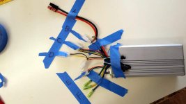
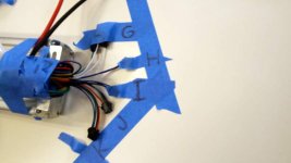
Alright, here's the controller pics. Explanations of what this rat's nest of wires are all for will be greatly appreciated.

To clear up some confusion--the battery had a red and a black thick wire. The wiring caps aren't permanent, just trying to rig up the system before I mount it all up. Voltage was measured at the battery only. And no blue spark, at least not yet. No smoke or bad smell, either. But I don't know what to do about precharge, so I am all ears.

Two pictures on the controller. Here's the key:

A -- Red and Black wires, battery connection

B -- Single Blue wire

C -- Five wires, black, yellow, green, blue, red? (maybe orange, I'm a bit colorblind)

D -- Three wires, Black, yellow, red--pigtailled out to black, yellow only

E -- Three wires, black, green, red

F-- Three thick wires, bullet connectors, green, yellow, blue.

G-- Three wires, each with own connector, green, white, white

H -- Two wires, blue, blue

I -- Three wires, green, blue, black

J -- Three wires, black, red, green

K -- red, blue, black, green

20150125_134119.jpg
 
K is for the LED panel. Blue is the ignition wire. The red is permanently live with battery voltage, so connects to blue to power the controller. Use a switch between them to switch the controller on/off. You can jump them for testing. The green is the signal for PAS level, which will default to level 1 without the panel. Black is ground for the panel.
 
D is for the brakes. Use the two wire connectors for brake switches and the three wire one for a hall-type brake sensor.
E is the throttle
I is the three position switch. You can get extra speed by putting a switch between the black and one of the other two. Use a jumper wire to test it.
J is PAS
H is cruise. Leave them disconnected. It's not very good. You can put a momentary switch between them, which will toggle the cruise on/off.
G The two white wires are speed restriction. The single green should have a partner single green, which are the self-learning. When you first use the controller, you connect them, and the controller figures out your phase/hall sequence and phase angle.
B is probably high-level brake.
 
D8veh,

Many thanks for unlocking that mystery.

So, if I don't have an LED panel, I connect the blue to the red on K? Maybe throw a switch in there?

Do I need an LED panel? And for that matter, do I need to install the PAS sensor, or will it work on throttle alone? I realized this old Schwinn tandem has a one piece crank and there is nowhere to mount the PAS sensor. I may find a work around, but would like to get the motor running meanwhile.
 
Yes, you connect the blue to the red. You only need the LED panel if you want to use PAS. The throttle should still work as normal.

Don't use more than 1/4 throttle until you confirm that the motor is running properly. Often, you don't need to do the self learning. If the motor knocks, judders or hums without moving, try connecting those two single wires. Once it's running properly, you disconnect them.
 
To answer Neil,

No big spark when I connect the battery to controller.

When I connect the voltmeter per your instructions, I get 50V at many, if not all connections.

However, after connecting orange and blue wires per D8veh's instruction, plus connect battery, motor and throttle, I get no response when twisting throttle.

The Calibike battery has a toggle switch on it. Still not sure of it's purpose.
 
50 volt is worrying.
Are you sure you are reading meter correctly , you shod maybe get battery voltage on one or possibly two wires.

A lot of the small red wires, on PAS, throttle etc should all have 5 vts or near 5 , maybe any where from 4-5 volts.

Of those wires with 5 volts on them, they should drop to zero when ignition wire is disconnected from main red.
 
After you joined the red and blue wires, check whether you have 5v on the throttle or PAS red wires, which tells you that the controller is switched on.
 
Another question to ask you ...
Did the controller come with the rest of the matching parts? like throttle, motor, LED display, PAS, Cruise Brake levers etc?


If it did, and they all have matching connectors that can only connect to one other device and that device only , then wiring of most of them is not the issue.

Just finding the correct ignition wire is the issue and that will be one of the 'free wires.

..there are too many unknown wires here really. lots of singles.

The fact that you do not have a single red wires is 'odd'

I'd have suspected ignition to be red, it usually is


But you only have two single wires ? with no matching connectors and a couple of odd pairs.
So :
pair of whites G
a pair of blue H
a blue B
a green. G
If either of the singles (B or G ) are not the ignition wires, and you have at one time connected them to battery voltage, then it may be too late. Firing 50 volt battery voltage on to a 'signal ' or '5 volt out' wire will not have done the controller any good, if it was not an ignition wire you may well have fried something .

Having briefly looked at some of the answer, i'd say some are wrong.
I say I think they are wrong, because you appear to have a block of 5 wires there, C in your picture is red, black, blue, yellow, green. That is a hall sensor block, almost 100% certain, and it connects to the motor right? If so then the pair of white CANNOT be a learning pair A "learning" plug is only for sensorless motors.

But, nothing is simple, I could be wrong....and that would be because the controller is Sensor OR sensor less type controller.
That blue pair 'could de to shoos sensor or not...don't know total guess. Depends on the plug(s) on the end of the blues. Can they be connected to each other?
Most of the white pairs I have seen are regen enable/disable. (Xie Chang controllers) ...Xlyte controller was also a pair of whites for sensor less, but rather than a single wire connector on each wire, it was a 2 pin connector, with a jumper plug that goes in to it.
.

You also mentioned a 'switch'. Is that the black box with the rocker in the photo? That could explain why you don't get the connection spark, because you are connecting the controller to the battery with the battery pack powered off.
Voltage across the Red and Black wires should go up when you flick the switch. It may not be zero as the BMS may hold voltage in capacitor even when off, and it may take some time to drain to zero. Does the voltage on between the red and black battery wires jump up when you flick the switch?
encinitas said:
A -- Red and Black wires, battery connection
Correct


encinitas said:
B -- Single Blue wire
Don't know. Any matching plug?


encinitas said:
C -- Five wires, black, yellow, green, blue, red? (maybe orange, I'm a bit colorblind)
Hall sensor to motor


encinitas said:
D -- Three wires, Black, yellow, red--pigtailled out to black, yellow only
I strongly suspect brake. It is wired to accept both a hall sensor brake (hence the red) and a normal swithc style brake lever.
That red should have near 5 volts on it. Connect voltmeter between black and red. If it is not 5 volts when controller is powered on then you have a problem. It should not be 50 volts


encinitas said:
E -- Three wires, black, green, red
Throttle or PAS.


encinitas said:
F-- Three thick wires, bullet connectors, green, yellow, blue.
Phase wires


encinitas said:
G-- Three wires, each with own connector, green, white, white
Do the whites have matching male / female plugs..so they connect to each other? Whites either learning or brake regen enable / disable...assuming this controller is following any sort of 'standard'


encinitas said:
H -- Two wires, blue, blue
No idea. do they have matching male / female plugs..so they connect to each other?


encinitas said:
I -- Three wires, green, blue, black
Again no idea. You'd need to check the outputs to see if any have 5 volt out. and which is ground. maybe this is PAS and E is throttle


encinitas said:
J -- Three wires, black, red, green
Again , same as I or E Could be throttle, or PAS


encinitas said:
K -- red, blue, black, green
Could well be this mysterious LED display, or a throttle plug for throttle that has a 'battery gauge'

Your throttle seems to have a switch, could be ignition.
Is that possible a battery gauge the three white ovals on the front of the throttle?
Would need to see the wire connected to the throttle cable
 
Sorry, work got in the way of seeking higher truths in the world of ebikes, but in the last couple of days, I got a key from the vendor on the wires in the controller. However, my controller does not have the ignition wire as shown in their diagram, so now I'm not sure I got the correct controller. Hopefully, I will get a reply overnight that will correspond with what D8veh has already suggested.

D8veh suggested connecting the blue and the red at K and that those were the ignition wires. I've done that, but now I need a bit of coaching on using the multimeter to understand both D8veh and Neil's instructions.

If I understand correctly, I hook up the red wires between battery and controller. I then use my meter to link the battery black wire to the PAS Sensor or suspected Red throttle wire to see if I have 5V running there. Is that the correct way to read the voltage?
 
I will try and answer the question about using the volt meter in a following posts, but, I spent an age typing out my last post with the quotes and all. In it I asked a few questions. If we are going to help you, please at least answer those questions.

Please go back, re read my post. and answer my Questions regarding the controller plugs and devices supplied, and sensor or sensor less etc. We cant help if you don't answer what we ask.

I'll start on a second post now, and go back to my previous post and highlight the questions in bold and red DONE

If you quote each question as you answer it will make our lives easier to help you.

When you quote you need to first hit the quote button on my entire reply and then add and remove the quote 'codes' as below
You need to go to the end of my question then add the end quote marker after my question, followed by your answer then the 'Open quote again

If you cut what is in the code box below, and paste it after each of my question..and answer in the middle of the quotes

Code:
[/quote]

Your answer goes here

[quote="NeilP"]
 
Back
Top