Conundrum in Throttle wiring to controller

Joined
Jan 22, 2015
Messages
17
Location
Chennai
I have a Chinese throttle, and there were no manual for reference. How to find which wire is positive, output and ground signal?
This Throttle has 4wires coming out, one should be for the push type button mounted on the throttle.
Besides color coding, how do we identify each signal wire?
I want to know some technical explanation. Please help me :?:
 
Is it a hall sensor type or a potentiometer?
If you have a multimeter, switch it to resistance or continuity and check the individual poles. The pole for the switch should be easy to find. Just switch it on and you should have a shortcut between to poles.
What colors do the wires have? It should be something like red, green or white and black.
 
amberwolf said:
You could try a search on the bajillion times this has been asked before.
I had done it sir, but couldn't find the suitable solution for my problem. I'll upload more info on my problem asap.
 
It's nearly universal that red is 5v supply and black is ground. That only leaves two wires to figure out. Does the throttle have LEDs?
 
Actually I bought the throttle from the same place where i got the controller, so they matched easily.I had connected and cross checked everything ,
Battery to Controller,
Precharge resistor,
Kill switch,
Fuse,
Hall sensors to controller,
Phase wires to controller,
Throttle to controller.
After allowing the power supply, i couldn't see any motion in the motor even after putting some throttle. I checked the connections at connectors as well, everything was perfect and power is flowing to the controller but i couldn't see any output from the controller to motor.
I surfed a lot on powering the controller on the forum but couldn't find ,
My controller is some cheap chinese 36v controller with the same silver colored casing outside(what we generally see when we google chinese controller).
1) Will be there any provision to ON/OFF the controller in these type of custom controllers?
2)How to check whether power is flowing from controller to motor?
3)How to check whether controller is powered or not?{ some sort of arrangement we see in KELLY/ Curtis controllers}
4)How to check whether the throttle connections on the controller?

I'm actually new to this field, i just wanna learn things.
Im attaching the picture sent by the dealer showing the connections, but i couldn't make any best use of it.
[ with reference to picture, Im not using
a) Front brake lever with switch
b)Rear brake lever with switch
c)Grip with horn switch
d)Head light
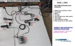
Angel Y wiring connections.jpg
this is the reference picture


This is the controller i have it right now
 
So you don't have all the parts in that kit? If your motor didn't come with that controller as a kit, then you will have to figure out the wire order for phases and halls.

Look in the Wiki, I think, for how to do that. Typically I start by swapping two colors, like blue and green, on both halls and phases, try the 9 combinations. If that doesn't work, then try swapping colors on just halls or just phases.
 
A throttle is the cheapest item to buy a second "back up" part for. Even if I don't think a problem with a kit is the throttle, I will swap-in a different throttle that has proven to work with another kit. [as far as calculating which wire goes where when the wire color-codes don't match, I don't know the right answer to that, meaning I don't know how to trouble-shoot and identify]

My second trouble-shooting method is to switch-in a sensorless controller (usually a cheap and small 6-FET, often found for under $50). If the stock controller doesn't work, but the sensorless controller DOES work, then...the hall sensors inside the motor may be the problem, but...at least at that point you know the problem is NOT the motor (since the motor works with the sensorless controller). Some controllers have a "auto-detect" feature, where it will figure out the proper order of hall sensors, and then it will internally re-configure itself to run with the hall-sensor arrangement in the motor you have. Controllers with this feature are more expensive, but I plan to buy one soon for trouble-shooting in the future...

The motor is often the most expensive part in a kit, so it would be the most trouble to buy a spare. However, over time I have accumulated a couple spare motors which I may build onto "yard sale" bikes as a back-up, for friends to test-ride, and for my own personal trouble-shooting "swap-in".

Best of luck with this issue...
 
I just got a new controller and throttle and the wires on the throttle were reversed from the controller. I just switched them around so red=red, black =black and blue equaled green (the other signal wire). It worked fine after that.
otherDoc
 
First you have to check that the controller is active. Measure the voltage between the red and black throttle wires while it's switched on and connected. 5v says the controller is on 0v says it's off, even if you have it connected to the battery.
 
solved,
there is an ignition for powering the motor controller and the throttle was previously matched.It was amazing seeing my E-Bike running for the 1st time.Thanks guys.
I would like to explore controller section,since i feel myself a pro in batteries and connectors :p
i'll upload pics tomorrow.
 
Hey guys,
Today i had tested a motor of Indian make[ SIKCO i guess] with the controller of different make[ Ampere Electric vehicles ltd.] .
The motor controller was powered and power is supplied to the motor but the Hall sensors weren't in good mood i guess ,the motor started vibrating to and fro at very less throttle.
I read the precautions and placed a very less amps fuse[5 Amps] .
This led me to open the 36 combination chart and try one after other.
But what i found is One of the combination was a bit rough though it is forward in motion.
I could also see no reverse motion in any of the combination.
QQxD50ul.jpg

Seems like i have to try one more time tomorrow making sure i had done every combination correctly.
 
d8veh said:
First you have to check that the controller is active. Measure the voltage between the red and black throttle wires while it's switched on and connected. 5v says the controller is on 0v says it's off, even if you have it connected to the battery.
Yeah.... there existed an ignition switch,which i had make it by shorting two of the wires on this damn chinese controller.
 
dogman dan said:
So you don't have all the parts in that kit? If your motor didn't come with that controller as a kit, then you will have to figure out the wire order for phases and halls.

Look in the Wiki, I think, for how to do that. Typically I start by swapping two colors, like blue and green, on both halls and phases, try the 9 combinations. If that doesn't work, then try swapping colors on just halls or just phases.

Bingo!.... Got it. Two days back i had tried all the 36 Combinations and that didn't go well( I could see only Vibrating motor).
Yesterday,I just thought of checking whether the Hall sensors are having a proper connection with the controller side.
I checked on the continuity of each Hall sensor wires from the motor side and found the Green Hall wire has some problem.Immediately i swapped it with some healthy wire and then i tried the combinations,
after 10 minutes i reached SMOOTH REVERSE motion of motor and 5 minutes later i can see the wheel spinning SMOOTH FORWARD MOTION.
I checked the current rating,which was normal.
Thanks to ES members for the support and I will keep updating my problems and success trials in future[ sticking back to ES Forum Rules].
zCsb5Mhl.jpg

aEwbH52l.jpg

7oay6Iul.jpg

EojhX4jl.jpg
 
spinningmagnets said:
A throttle is the cheapest item to buy a second "back up" part for. Even if I don't think a problem with a kit is the throttle, I will swap-in a different throttle that has proven to work with another kit. [as far as calculating which wire goes where when the wire color-codes don't match, I don't know the right answer to that, meaning I don't know how to trouble-shoot and identify]

My second trouble-shooting method is to switch-in a sensorless controller (usually a cheap and small 6-FET, often found for under $50). If the stock controller doesn't work, but the sensorless controller DOES work, then...the hall sensors inside the motor may be the problem, but...at least at that point you know the problem is NOT the motor (since the motor works with the sensorless controller). Some controllers have a "auto-detect" feature, where it will figure out the proper order of hall sensors, and then it will internally re-configure itself to run with the hall-sensor arrangement in the motor you have. Controllers with this feature are more expensive, but I plan to buy one soon for trouble-shooting in the future...

The motor is often the most expensive part in a kit, so it would be the most trouble to buy a spare. However, over time I have accumulated a couple spare motors which I may build onto "yard sale" bikes as a back-up, for friends to test-ride, and for my own personal trouble-shooting "swap-in".

Best of luck with this issue...
Today it was really a beautiful day for me though its so hot outside...Every issue was settled down and Motors started spinning at good current consumption.
While coming back to home,the bike stopped all of a sudden and i checked for the fuse and low voltage on the battery.
Fuse is OK
Battery =25V !
I should have pedalled.. i knew i over discharged the batteries.
But i couldn't understand is ,what might have kept the Bicycle off...
I was thinking of a low voltage cutoff might had done this.What do you think ?
What are the general issues one might meet while the rides..
Ok i'll just check on the controller and batteries and come back!

EDIT:- It is the Low voltage cutoff mechanism that put my E-bike off. Everything is fine
 
Back
Top