You are using an out of date browser. It may not display this or other websites correctly.
You should upgrade or use an alternative browser.
You should upgrade or use an alternative browser.
INFINEON CONTROLLERS FOR DUMMIES
- Thread starter Knuckles
- Start date
Knuckles
10 kW
Hmmm ... for the transistor mod ... Let's see ... the ignition wire only draws 60ma and my bats are NEVER more than 100V so ...solarbbq2003 said:Would 1n4148 be suitable 100v fast switch diode?
http://ronja.twibright.com/datasheets/diode/1N4148_1N4448_5.pdf
100V 200ma ... works for me! 8)
WTF are you asking?solarbbq2003 said:If I were to use separate power supply to run the board ( eg. small 12v cell) would it be a simple matter of connect pos/neg to where the regulator is, or more complex?
YES! The ignition circuit only draws 60ma. Sure you can use ANY voltage source for that. But Why?
The point of the transistor mod is so the ignition circuit and the main (POWER MAKE BIKE GO) mosfet circut can pull from the SAME bat source.
John in CR
100 TW
Just sell me 2 with serial cable input (like my Kelly brushed has) to connect to a PC. I want all the bells and whistles (CA plug in, variable LVC, max voltage and amperage (with limits), regen, atomic and solar power, etc  ) and simple instructions for all possible items to set. Before closing it up, just pot the whole thing in epoxy, so it's waterproof too. IOW, a black box where I can change as many things as possible, and all I have to do is get the phase and hall wires right.
John
John
Knuckles
10 kW
Wrong post ... You want the "INFINEON CONTROLLERS FOR PEOPLE ON ACID" thread!John in CR said:Just sell me 2 with serial cable input (like my Kelly brushed has) to connect to a PC. I want all the bells and whistles (CA plug in, variable LVC, max voltage and amperage (with limits), regen, atomic and solar power, etc) and simple instructions for all possible items to set. Before closing it up, just pot the whole thing in epoxy, so it's waterproof too. IOW, a black box where I can change as many things as possible, and all I have to do is get the phase and hall wires right. John
Knuckles said:You want the "INFINEON CONTROLLERS FOR PEOPLE ON ACID" thread!


I should be able to contribute to that thread. :wink:
Knuckles
10 kW
[youtube]wdZfiwdZWxo[/youtube]
John in CR
100 TW
That's a brushed Kelly that I've had for almost a year. You guys are connecting to Infineons with your computers, so why is it an acid trip for a customer who's bought a kit, 2 motors, and 5 controllers to ask for the same already made? Then I can do my own upgrades as you discover more capabilities.
John
John
Knuckles
10 kW
It's called technology. It changes every day. Every day we learn more and every day things get better  and also maybe hopefully cheaper (less expensive).
Right now we (me, Keywin, Geoff57, philf, ZapPat, fechmeister and a few others?) are interfacing controllers with PCs.
We've gone from a PC serial COM port to a USB interface (inspired by Geoff57 and philf).
Heck ... ZP is building a PWM WMD from scratch with a "cranial implant" interface!
J_in_CR ... Nothing prevents you from buying this ... http://cgi.ebay.com/72V-1500W-brushless-controller-for-E-bike-scooter_W0QQitemZ300276897869QQihZ020QQcategoryZ11332QQcmdZViewItemQQ_trksidZp1742.m153.l1262
and making it do this ... http://endless-sphere.com/forums/viewtopic.php?f=2&t=8457&start=30#p130539
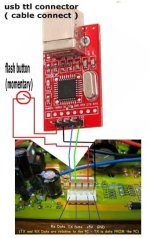
And soon (hopefully soon) there will be a standard Infineon USB-TTL interface (like this maybe) ... http://endless-sphere.com/forums/viewtopic.php?f=2&t=8317&st=0&sk=t&sd=a&start=75#p128713
It takes time to invent ... test ... and produce these goodies ...
Ergo ... This Thread!
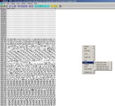
Below is a screen shot of the program running in the debugger.
It looks like hacking, er, uh "customization" is possible. It would be helpful if I actually understood some of that hexadecimal stuff. After scrolling through a zillion lines of code looking for non-jibberish, it feels just like a flashback.
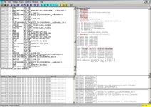
It looks like hacking, er, uh "customization" is possible. It would be helpful if I actually understood some of that hexadecimal stuff. After scrolling through a zillion lines of code looking for non-jibberish, it feels just like a flashback.

Knuckles
10 kW
Fishmasterdan
100 W
Post for dummies.
Do you need to add a 2 pole fuse or a 1 pole fuse?
What is largest fuse I can put in a 50a unit?
Is there a switch that can be used to turn power off (like stop the massive capacitor draw )before I plug the batteries in and stop frying my connectors?
What is the upper limit of temperature??
There is NO saftey feature's built into this unit what is NEEDED to protect my investment??
What is the max voltage the controller can withstand??
What does the yellow wire actually do?
What does the blue wire actually do?
How do you hook up the "key switch wire" what do I need for the key switch if I want a key switch?
What kind of throttle do I need and where do I buy them if I dont want a full size?
What kind of connectors are needed for the battery/hall sensor ect??
How do I change the LVC ?
These are all questions I have had or heard from others than I can think of (trying to get them all here) I will add more as I remember hear or read them.
Answer away
ZapPat
10 kW
John,John in CR said:That's a brushed Kelly that I've had for almost a year. You guys are connecting to Infineons with your computers, so why is it an acid trip for a customer who's bought a kit, 2 motors, and 5 controllers to ask for the same already made? Then I can do my own upgrades as you discover more capabilities.
John
I've noticed a few times that you are working on a dual motor bike, and I'm seriously going to try this myself with two direct drive hub motors. Mostly for added handling in slippery conditions (ice, etc). I just had my first spin using one tire with about 120 screws added to it, and it gave most encouraging results (think wheelies on slick ice surface). So now for two tires like this, and eventually two motors synchronized together to have a great 2WD setup. I think the trick to really good handling is the synchronisation of the two wheels... which of course will require some customization to work. However, I think this will not be a big deal to do for me since it's not a matter of "hacking" anything in my case, but more like "adding features" into the controller's program. I plan on using a serial data link to connect two seperate controllers together, and have a slightly different firmware (program) than the usual one loaded into both of them. I tell you, compared to building an advanced controller from the ground up, this type of feature isn't that exotic!
Anyways, my point with this is kinda like Knuckles says, it takes times and patience to get everything right, but be assured that in the near future I hope to provide a really cool controller alternative to all the ebike power users that love to mod their ride's behavior easily. I'll update my controller build thread soon, so keep your eyes peeled and let me know if you have ideas or comments!
(sorry for the thread pollution, Knuckles...)
John in CR
100 TW
ZapPat,
I'm not sure what you mean by synchronized, since the wheels travel different surface distances it's not possible. Your ice e-bike sounds like loads of fun, and I look forward to being able to use all this new controller stuff instead of just read about it.
John
I'm not sure what you mean by synchronized, since the wheels travel different surface distances it's not possible. Your ice e-bike sounds like loads of fun, and I look forward to being able to use all this new controller stuff instead of just read about it.
John
Knuckles
10 kW
I use inexpensive glass fuses in an easy access fuse holder inline right off the main battery positive.Fishmasterdan said:Do you need to add a 2 pole fuse or a 1 pole fuse?
I also start with lower amp fuses. If it blows I go up 5 amps. I never go higher than the rating of the controller.
I also keep spare fuses stored on the eBike.
Some folks use resettable circuit breakers.
50 amps. But start lower and work your way up to 50 amps.Fishmasterdan said:What is largest fuse I can put in a 50a unit?
Better to blow a 20 cent fuse than to melt wires or destroy a motor or controller.
The thin red controller "ignition" wire only draws 60 ma. A simple toggle switch can be used.Fishmasterdan said:Is there a switch that can be used to turn power off (like stop the massive capacitor draw )before I plug the batteries in and stop frying my connectors?
The thick red wire is the MAIN POWER to the mosfets. This is the power that makes the motor run.
The MAIN POWER wire can be connected all the time. When the ignition is off, the MAIN POWER current draws less than 10 ma.
The MAIN capacitors in the controller will stay charged for a long while even after the MAIN POWER is disconnected.
It is good practice to check both the MOTOR and CONTROLLER temperature by hand.Fishmasterdan said:What is the upper limit of temperature?
HEAT is the enemy. Both the MOTOR and CONTROLLER can overheat if you push them too hard.
I prefer to ride so that neither the MOTOR or CONTROLLER get more than moderately warm (50 Celcius).
1) Use a master fuse.Fishmasterdan said:There is NO saftey feature's built into this unit what is NEEDED to protect my investment?
2) Check MOTOR or CONTROLLER temperature by hand on a regular basis.
3) Get to "know" your system first then SLOWY start to push the limits.
4) Use Common Sense and your system will last indefinitely.
Depends on the controller purchased. The 50 Amp Infineons I sell ONLY use 100V mosfets and 100V capacitors.Fishmasterdan said:What is the max voltage the controller can withstand?
The transistor mod opens the safe voltage window with a Max safe voltage up to 90V.
The R12 mod will increase the Max regen voltage from 60V up to about 84V.
See ... http://98.131.176.65/endless-sphere/Infineon_Wiring.jpgFishmasterdan said:What does the yellow wire actually do?
See ... http://98.131.176.65/endless-sphere/Infineon_Wiring.jpgFishmasterdan said:What does the blue wire actually do?
See ... http://98.131.176.65/endless-sphere/Infineon_Wiring.jpgFishmasterdan said:How do you hook up the "key switch wire" what do I need for the key switch if I want a key switch?
The thin red controller "ignition" wire only draws 60 ma. A simple toggle switch can be used.
The infineon controller uses a hall effect throttle.Fishmasterdan said:What kind of throttle do I need and where do I buy them if I dont want a full size?
See ... http://www.electricscooterparts.com/throttles.html#hall
OR ... http://stores.ebay.com/HuaQiang-North-Road_W0QQssPageNameZstrkQ3amefsQ3amesstQQtZkm
The stock controller comes with typical "Chinese" connectors.Fishmasterdan said:What kind of connectors are needed for the battery/hall sensor ect?
See ... http://www.electricscooterparts.com/wireconnectors.html#throttle
Many folks cut these off. Some will hard wire (no connectors at all).
Some folks use Andersen Power Pole ... http://www.powerwerx.com/anderson-powerpoles-accessories/individual-housings-contacts-roll-pins/
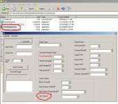
The LVC can be set in the software. Then "flash" the MCU with a PC interface cable.Fishmasterdan said:How do I change the LVC?
Some folks also install a poteniometer to alter the LVC.
See ... http://endless-sphere.com/forums/viewtopic.php?f=16&t=7361#p110932
ZapPat
10 kW
I'm moving this over to the 2 motors, 2 controllers, 1 throttle + 1 switch thread so as to not invoke Apollo's wrath!John in CR said:ZapPat,
I'm not sure what you mean by synchronized, since the wheels travel different surface distances it's not possible. Your ice e-bike sounds like loads of fun, and I look forward to being able to use all this new controller stuff instead of just read about it.
John
Knuckles
10 kW
That's Leonidas. 8)ZapPat said:I'm moving this over to the 2 motors, 2 controllers, 1 throttle + 1 switch thread so as to not invoke Apollo's wrath!
BTW ... I built the 2x2 already. Works great ...
[youtube]Xdra4oMniIE[/youtube]
Rear "Bafang" ... Front "Wan Lian" ... 2 Infineon controllers ... 1 throttle ... Need more bats.
The ride is incredible. 2x2 power handles so different than single wheel power.
Fishmasterdan said:What does the yellow wire actually do?
The controller has two inputs for brake signals. The yellow wire will activate the brake cutoff when it sees a positive voltage higher than about 5 volts with respect to battery negative. This is intended for systems where a brake light is being used and the wire goes to the brake light + wire.
The other brake input is the black/yellow pair. This is intended to go directly to a brake lever switch that is not connected to anything else.
You can use both types of inputs at the same time. Both have the same effect.
Fishmasterdan said:What does the blue wire actually do?
Yeah, what does the blue wire do?
Is that an input or an output?
Knuckles
10 kW
It's an OUTPUT.fechter said:Yeah, what does the blue wire do? Is that an input or an output?
The blue wire is ONLY really used for a CA speed INPUT ... Wire 5) as shown here ...
http://endless-sphere.com/forums/viewtopic.php?f=16&t=7361#p110932

philf also started a thread about it here ...
http://endless-sphere.com/forums/viewtopic.php?f=2&t=8613
It's just an amplified hall signal output.
Keywin adds it on all the Infineons because I guess it 'don't cost nothin'.
I never use it myself.
But it does come in handy for a CA-DP ...

http://www.ebikes.ca/drainbrain.shtml
HECK! For all I know it might work on ANY "Speedo-Meter" thingy.
solarbbq2003
10 kW
- Joined
- Apr 7, 2007
- Messages
- 500
solarbbq2003
10 kW
- Joined
- Apr 7, 2007
- Messages
- 500
solarbbq2003 said:did a word doc tried to put most of knuckles info into one doc, hope you dont mind knuckles!
By the way going through trying to put all info into one doc I realised how much effort you've put into it , a huge effort.
solar your idea of putting all the info together into one file is a good one I kind of beat you to the idea though with this http://endless-sphere.com/forums/viewtopic.php?f=16&t=7531 I posted that weeks ago as a pdf, I have been too busy testing and finding out everything the Infineon can do now to update it, glad you've taken over documentation I just have not got the time.
A pdf file would be better though the software required to open it is free ,the file is smaller and it wil cros platforms more easily, other than that good work.
Geoff
Knuckles
10 kW
solarbbq2003 said:did a word doc tried to put most of knuckles info into one doc, hope you dont mind knuckles!
By the way going through trying to put all info into one doc I realised how much effort you've put into it , a huge effort.
Be my guest! 8)
I believe information SHOULD be free and easy.
Hey Brett ... your Australian! This is good.
Can you get these? http://www.cutter.com.au/proddetail.php?prod=cut508
from ... http://www.cutter.com.au/
I have an idea for an "ice cold" ANY VOLTAGE 21V-84V Infineon with power to spare for 12V ebike lighting.
Actually the "R-78HB6.5-0.5" would have the best efficiency.
I just can't find it in USA for less than $25.
(btw ... This idea was inspired from ... http://endless-sphere.com/forums/viewtopic.php?f=2&t=8457&st=0&sk=t&sd=a&start=60#p132993)
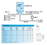
high res pic here ... http://98.131.176.65/endless-sphere/idea.jpg
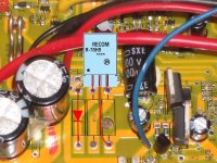
The part would install vertically on the pcb like this ...
(Ha Ha ... Any Voltage Controllers for "Dummies" :lol: )
Cutter Electronics
Unit 12/ 137-145 Rooks Rd
Vermont, Vic 3131
Mob 0417 540 359
Phone +61 3 9873 5088
Fax +61 3 9873 5099
Email mark.riley@cutter.com.au
Qld Distributor
Keith Buettner
Digital Linear & Passive Components
8 Manor Drive Wellington Point
Brisbane 4160 Queensland Australia
Ph (07) 3207 1398 in Australia
Fax (07) 3207 5160
Mob 0410 076 343
Email: dlpc@bigpond.net.au
solarbbq2003
10 kW
- Joined
- Apr 7, 2007
- Messages
- 500
hi geoff, looked at your pdf, looks like a good summary, I took liberty of cutting pasting lots of knuckles more detailed info in the word doc, haven't tried doing a pdf before.
regards the recom dcdc concverter can organise from australia knuckles no probs, i'll check china also see if available over there. What would be the diode you would use shown in the pic?
regards the recom dcdc concverter can organise from australia knuckles no probs, i'll check china also see if available over there. What would be the diode you would use shown in the pic?
The shottky is in series at V+(in). So it looks like a protection diode in case of revers polarity.What would be the diode you would use shown in the pic?
May be a blocking series-shottky at V+(out) should de recommended as well, preventing harmful back current, when the Recom is powered down.
Georg
philf
1 kW
Just curious to know if anyone is actually using a direct CA interconnect to the Infineon as pictured here...

The pesky signal is the one I've posted about elsewhere - the speed (blue) wire. Expecting to see something like 23 pulses per wheel rotation on this line (with the particular motor I'm using), I was stunned to see a horrendous onslaught of noise as soon as you start to even gently spin the wheel (even by hand). At first, I thought it was just the controller I was testing with (which is the one I put the switcher in - I wondered if I'd discovered a noise problem with THAT). But I've tried two other controllers, one completely virgin, and - same thing.
The first time I saw the "Speed Indicate" dropdown in the programming software, I thought "Ah HA!"... But the document that geoff57 posted indicates that this setting, in fact, is used to tell the microcontroller how to interpret the speed-related jumpers on the board.
I'm wondering if the signal just needs some kind of conditioning. I had a similar problem with false data from the first GM controller I added the speed sensor to. To GUARANTEE that the wheel was moving (and not just juddering), I actually threw together a quick perfboard circuit that fed all three hall signals into a 74LS138 (3 line to 8 line decoder), and then used two of the outputs from THAT to toggle the set/reset pins on a 74LS74. The result was a signal you could take to the bank, as the motor had to pass through at least TWO phases in the overall commutation pattern to produce a blip (the outputs on the '138 that were used were two patterns apart).
I was hoping the signal on the Infineon was going to be as robust...
Similar threads
- Replies
- 3
- Views
- 427
- Replies
- 12
- Views
- 286


