Cyclone Motors Exposed! Totally Naked Pictures

rkosiorek

100 kW
Joined
Jan 18, 2007
Messages
1,770
Location
Belleville, Ontario Canada
First off, I did not take these pictures. these were taken by Bill Bushnell of his Cyclone motors. he has a bunch of them. He also published them on the net on his own website:

http://bushnell.homeip.net/~bill/bike/pictures/cyclone_motor/pages/page_1.html

I just reproduced them here with his permission. you can download the pictures on his site with higher resolution.

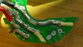
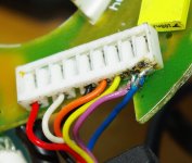
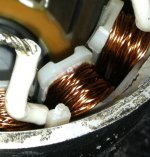
So here goes. first a few pictures of the GUTS of the planetary gear box. the comments are also bill's

001.jpg

002.jpg

003.jpg

004.jpg

005.jpg
 
zip file of the Hi-Rez version of these pictures
 

Attachments

  • gearbox.zip
    5.8 MB · Views: 229
now for some of the innards of the 360W motor with internal controller. this was his first motor, so he was a little reluctant to disassemble it completely.

001.jpg

002.jpg

003.jpg

004.jpg

005.jpg

View attachment 2

007.jpg

008.jpg
 
Hi-Rez zip file of the 360W motor
 

Attachments

  • 360W internal controller.zip
    7.2 MB · Views: 260
photos are geting big. i had to break the 500W Hi-Rez zips into 2 posts to upload them. so here is part 1.
 
part 2 of the 500W Hi-Rez
 

Attachments

  • 500W internal controller part 2.zip
    6.7 MB · Views: 252
now what we have all been waiting for. this is the 500W motor with external controller. it is the same as the 650W and the 900W. the 650W and 900W are the same motor but the 650W uses a 36V controller and the 900W uses a 48V controller. the difference is only n the controllers.

001.jpg

002.jpg

003.jpg

004.jpg

005.jpg

006.jpg

007.jpg

008.jpg

009.jpg

010.jpg
 
part 1 of the Hi-Rez zip photos
 

Attachments

  • external controller part 1.zip
    8.4 MB · Views: 264
and finally part 2 zip
 
bill also tried every possible combination of phase and hall sensor wires to determine how to switch from CCW (NORMAL) rotation to CW rotation.
he compiled this chart of his results

View attachment c8tf3h.pdf

the original can be viewed on his website:

http://bushnell.homeip.net/~bill/downloads/cyclone_hall_power_leads.pdf

many thanks to bill for his excellent photos. i decided to post them here as this forum is more public. bill also hangs out at that "other" forum ie. the yahoo "power-assist" group.

rick
 
One of the things that he has mentioned is that when wired to work in reverse or CCW, the motor runs slower. i advanced the theory that the motor timing has been advanced to optimise it to run in one direction. the Hall sensor PCB clips into place and it looks like it can be set to one of 3 positions.

TIMING.jpg

I have asked bill to test the motor using the other two possible timing positions and report on how it affects performance. hopefully we will have an update soon.

rick
 
well you can go one step further, you can take out the stator from the case, not difficult, technique is put piece of wood large dia round vertical on ground, put the inverted motor over it, and bash the whole thing down on concrete, the inners will come out, puting back in same process reversed, but you hitting the casing on the ground, inertia of stator puts itself back into the case. hope makes sense.
Also the hole in the side of the case make easy to put the three thick winding wires to the outside and then can use a sensorless type controller with the motor, if inbuilt controller damaged no need to replace it, just use a sensorless type ( one that is immediate start type)
warning following picture contains graphic nudity of cyclone inners, over 18 viewing only
 
i warned ya
stator removed cyclone.jpg
next pic running three thick wires out for sensorless controller, could glue in some hall sensors and used sensor type controller but easier with sensorless.
cyclone sensorless controller mod.jpg
 
Thanks for the pics Rick.

That's an interesting rotor design. It is not optimized, though, since a lot of the flux will be shunted by the iron on the sides of the magnets. At least it shouldn't fly apart too easy.

I see there looks like a lot of empty space in the stator too. More copper could fit in there.

You are probably right about the timing but the spacing between the index holes seems like a lot. A sensorless controller would make that moot.
 
Bill Bushnell was busy with his external controller Cyclone. he modified the hall sensor boards to adjust the timing. he also found that the motors do have advanced timing as shipped and do favor the CW rotation. by adding a couple of holes he did find the neutral spot. these photos detail his experiment.

View attachment 5

002.jpg

003.jpg

004.jpg

005.jpg

006.jpg
 
I thought my cyclone motor was bad and opened it up to check the bottom bearing. It was fine. Of course I hacked it as I got into it, cutting the wires and pulling out the two yellow wires. Can I skip the circuit board for the red white and black wires and wire them directly? Also what are the two yellow wires for? Are they for a heat sensor and are they needed? I got the whole setup for cheap including controller, crank engine mount etc. I would like to get it back together.
Thanks in advance!
 

Attachments

  • 2.jpg
    2.jpg
    240.6 KB · Views: 8,869
  • 3.jpg
    3.jpg
    202.8 KB · Views: 8,869
the yellow wires are for a thermistor temperature sensor.

the board also contains 3 hall sensor chips that are needed for motor timing. these are needed for sensor controllers, which are the most common kind and likely what came with your motor. this is what 5 of the thin wires are connected to on the little connector.

you would need to get a sensorless controller to run the motor without this board.

rick
 
Rick,

Thanks for the feedback. I plan on using the board but I was thinking of wiring the black white and red wires directly. I know I need to use the hall sensor setup with my controller.

1. Is there a problem with wiring the black red and white wires directly??

2. Would it run without the yellow wires attached?? The guy that had it before me, kept having the motor shut down on him, so I think it might be due to the temp sensor shutting it off too soon. There is no evidence of motor damage from overheating.

Gracias!
 
Running the phase wires direct is not a problem however there is no real benefit either and you run the risk of them shorting to one another or the motor body if left loose ie. not soldered to the board.

The temp sensor is in there to shut the motor down if it overheats. I have found they only overheat if run too slow for too long. Keep the motor spinning fast, I mean noisy fast and it wont overheat. If you remove the sensor and the motor overheats you will melt the insulation on the poles and destroy the motor. See the photo below of an over heated pole. Notice the bubbling, all 4 poles on that phase were the same and I had continuity from phase to motor body. This motor never worked after this.
 

Attachments

  • photo.jpg
    photo.jpg
    66.5 KB · Views: 8,821
maxwell92036 said:
even with my reading glasses on I couldn't see the damage real clear, but with my camera and a blow up it is pretty evident. So what is happening here?


your looking at a quickndirty hackjob on a couple wires that no doubt broke off from excessive tension.
in trying to solder crimp pins the insulation got melted back leaving the two bare wires exposed.
there is a risk of the same pulling force that broke them in the first place shorting them together.
it could just be a red herring but it does look awfully close.
 
the 2 melted wires are actually the ones for the temp sensor.

rick
 
subscribed !
 
Quick question, the thermal cut off on the cyclone is sensed with a thermister in the motor and controlled by the controller not the motor itself, so by moving over to an Infineon controller like a Lyen, you loose the thermal cut off feature? Anyone know about this?
 
Back
Top