Freewheel Jack/Crank-Shaft Adapter for Amberwolf's CrazyBike

amberwolf

Administrator
Staff member
Joined
Aug 17, 2009
Messages
40,859
Location
Phoenix, AZ, USA, Earth, Sol, Local Bubble, Orion
I have an adapter I'd like to make for CrazyBike2's jackshaft crankshaft, the one that receives the chains from both motor and pedals, to allow me to thread freewheels on it. This thread is essentially a call for resources and help to make one, and an explanation of why I want to use it, how it works, etc. I suspect others could use one too, if it already existed, but I haven't found one so far.

I once had something similar almost working, but it wasn't threaded on, I had to weld (into the threaded core of the freewheels) in washers I had filed the holes out square, to fit them onto a square-taper crankshaft, two of them side by side on the left side, so the motor and the pedals would not drive each other, and I could space the chainrings I attached to these freewheels farther apart than a simple triple chainring typically is, to prevent some of the problems it's been plagued with regarding chain derailing and tangling.
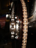
ChainlinesFromRear.JPG
But nothing I could use to make those center-filler bits that I could still file would hold up for very long with even just the pedal forces at startup, and I sheared thru them quickly. Worse, welding onto the freewheels softened and destroyed the core piece, so the races and the pall bits broke away, so I wound up welding the freewheel inner and outer races together so I could continue using the bike, until I finally got fed up with fixing and remaking the cores with the filed-out holes, and just ended up using a regular bike triple (double sometimes) chainring there.
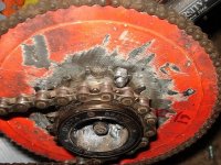
Pedal&MotorReceiverChainwheels.JPG
I designed an adapter even before I tried out the above, but don't have a way to make it. I can probably machine aluminum to the right size and shape, maybe, on my lathe, but I can't accurately make the hole for the square taper crankshaft, nor can I thread the inside and outside of it.
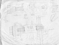
Crankshaft Freewheel Adapter 1.jpg
I might be able to drill and carefully file out the square taper hole, but I am not sure I can do it well enough to keep it all centered and balanced, unless I *start* with doing that hole first, then cut a sacrificial crankshaft (which I don't really have to spare) so I can chuck it up in the lathe, tamp down the unit on, and lathe away until it's cylindrically lined up with the square taper hole, and the right diameter to then be threaded outside. However, I then can't get it *off* the square taper shaft unless I have also first drilled out the hole on the other end, and tapped it's threads so I can use a crank puller on it. I don't have a way to tap these threads, and all the taps/dies I have found for these sizes are very expensive (usually at least $50 each, not including shipping, and I would need two sizes).
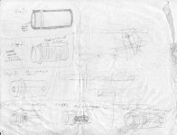
Crankshaft Freewheel Adapter 2.JPG
It doesn't have to be made with the outer lip, as I can probably use a pair of the lockrings off of crankshaft bearing races, plus spacer rings, to keep the freewheels from coming unthreaded.

It also probably doesn't have to be as long as it seems in the pic; I never determined if there is a "good enough" length for it, but I wanted it to be wider than just two freewheels, so I could space them as needed along there with shim washers between them to get whatever alignment with the pedals and motor I need (since obviously that isn't working out very well the way I have been doing it so far). Right now I am guesstimating 3" long.

Preferentially, I would like to get two of those oddball one-long-side crankshafts like the Cyclone kits have, to put one on this jackshaft to hold this device, and one on the pedals to make the chainrings on them stick out farther from the frame (there is a clearance problem with the batteries right now, preventing me from putting a side cover on there, among other things).

It also should be long enough so that I can optionally attempt to use a regular freewheel cassette of at least a few speeds, on the inside end (right) of it, in addition to the pedal freewheel. That way I can even have the motor shift gears separately if I wanted to--something that would require a completely independent jackshaft right now. It probably won't work very well due to the alignment problems I've had before, but it has not been something I could ever try, yet. It'd also require a smaller chainring on the motor output shaft than I currently have.
 
I have thought of a few other things, but am not able to line them up quite right to make them work, such as taking two threaded bearing races from a bottom bracket and welding them end to end, and then welding those to the square taper nub cut from the center of a steel crank.

I thought I might be able to hold them together lined up by cutting a sacrificial crankshaft so it will chuck up in the lathe, then mounting the square taper nub on the crankshaft, tightening it down, and then removing the bolt. Then stack the BB races end to end on it, and use a longer bolt with a washer to fix them to the nub. Then spin the lathe by hand and shift them around until I got them lined up well, tighten the bolt more, and continue spinning and tapping the assembly until it is balanced, tighten the bolt to max, and weld it.

Several gotchas with that one, though:
--First, I couldn't find a bolt both long enough and with the right thread pitch and diameter.
--Next, I realized that I would have no way to pull the device off the crankshaft later if I needed to, as I could not reach the threads of the nub with a puller, and didn't have any other kind of puller that would be able to remove it without destroying it.
--Next I could not put the bolt itself back in place to keep it on the cranks securely against the motor pull (although I've never heard of cranks coming off even without a bolt in there at all, if it could happen, it would happen to me!). The holes in the BB races simply aren't big enough to pass a socket that could turn the bolt, and I didnt' have any of the allen-head types that would fit (I think I do now but the flange around them is too large to fit the holes, I think--havent' checked that).
--The threads from one BB race to the other don't line up this way, so I cannot thread them both on from one end. I would *have* to thread stuff on each one separately, and each would have to have it's own lockring to keep it from coming unscrewed outward. I could not get small spacing between them if i needed it, and I could not ever move the outer chainring inward much further than the edge of the outer BB race, potentially causing problems lining things up.
--I think there was another one but I forgot what I was thinking while typing the above. :(

Anyhow, this is one more step in the reason why I'd like to just machine a part for the purpose.
 
Amberwolf,
How commited are you to the Square bottom bracket shaft?

I can turn you a simple jack shaft & eliminate the square ends, Machine a keyway & you can mount any thing you want to it. the freewheel adapters can be added quite simply & alignment should be dead on.

I just made a simular unit for my long tail Comuter build yesterday (bottom bracket is now a suspension pivot)so I have a tool to cut the bearing race on a shaft.

I am adding a fully suspended extension (think extracycle) to my Tidalforce frame from oatnet. (pictures to come later)

Let me know what you need & I'd be happy to do the machine work for you.
(I want CB on the track next year for the death race!) T.
 
Thud said:
Amberwolf,
How commited are you to the Square bottom bracket shaft?
Well, the catch is that the other side of it (on the right) has to mount the standard triple chainring so I can shift front gears, too. Doesn't matter much just now but it will once I start trying to create a racer based on CB2. ;)

Square-taper hole in it does not seem like it'd be all that hard with a proper milling machine or casting it in there in the first place (which I considered doing from harddisk cases), but threading it sure is, without either the die and tap or the right gears for the lathe to do the cutting on it.

I suppose one other way to do it is to make a small adapter that goes onto the square taper shaft, with a keyway in it. Then a threaded adapter for the freewheels that slips on over that first adapter, with a keyway in it, too. Then (assuming I can find one) use a longer bolt of the proper thread pitch and diameter to match the ST shaft, with large fender washer, to secure everything to the inner shaft and provide the outer lip that keeps the freewheels from rotating off on the outer end.

I'd also like to get this design worked out because I think others could use it, too, for those that want to do a Stokemonkey/Cyclone type drive on a jackshaft for longtails like mine, where the pedals run from a forward-mounted BB rather than directly onto this one. I've seen other builds that look like they'd've been simpler if they had something like it, in my original researches about stuff that led to CB2.

I can turn you a simple jack shaft & eliminate the square ends, Machine a keyway & you can mount any thing you want to it. the freewheel adapters can be added quite simply & alignment should be dead on.
I *might* be able to do that sort of thing here, using the lathe to turn things and an angle grinder and dremel and files for keyways. Or running the tool on the lathe down the non-spinning surface, a bit at a time.

But I can't make the threaded parts for the freewheels to mount on; which puts me back to the same problem I have with the ST adapter. And I don't have a way to then mount the regular triple to it on the other end..

I tried another method once before any of the square taper stuff, and without freewheels at first, using just the core of a one-piece crank along with the bearings/etc. After cutting off the crank arms and finishing the ends, I built a thread-on adapter for sprockets, but discovered that the threads on both the crankshaft and the nuts and bearing races (after welding to them) used on these one-piece cranks are simply too soft, and almost any torque load enough to move the bare bike frame and wheels would also strip the threads.

I didn't think of trying keyways at the time, which might've worked, but I also had not yet realized I needed the regular triple on the right side to stay, and that I would need to be able to change the rings on that triple for experimentation or differnet motors, or even just because they will break when stuff goes wrong.

I considered one more possibility as well, of cutting the threaded part off of a couple of hubs, filing them down till the threads matched end to end, and securing those somehow to a cylinder welded to the crank nub described before; probably by welding and then filing around the welds to ensure the threads are cleared. I'd do it by keyway but I doubt there'd be enough thickness of the hub metal to put a keyway strong enough to hold anything in place, even with the freewheels threaded on there to help keep it from being stretched/swollen outwards by torque against it.

I just made a simular unit for my long tail Comuter build yesterday (bottom bracket is now a suspension pivot)so I have a tool to cut the bearing race on a shaft.
Do you mean that you have something hard enough to cut those thread-in BB races, but still leave them hardened? Because the only way I can cut them here is to anneal them first, which *probably* won't destroy the usability of the threads, but I'm not sure. It sure didn't help the freewheels any when I essentially did that by welding on them. :lol:

I am adding a fully suspended extension (think extracycle) to my Tidalforce frame from oatnet. (pictures to come later)
Sounds a bit like my cargo bike project using the Sierra and Trek frames, except that I'm not sure about the suspension part (since I am trying to do it as a no-weld setup that can be copied by anyone).

Let me know what you need & I'd be happy to do the machine work for you.
(I want CB on the track next year for the death race!) T.
So do I. :) Or rather, it's descendant, built for the purpose. ;) We'll call it cRaceyBike. :lol:


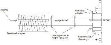
Anyhow, if using the ST shaft is untenable because it's not possible to make the adapter, then I need some help coming up with a jackshaft that lets me still put regular chainrings on the right side, of various BCDs if possible, in a triple configuration. I have a sort of idea on that, in that it could be a triple-stepped inverted top-hat, made as part of the jackshaft or as a keyed slip-on piece, perhaps with set screws to keep it from being able to slide sideways. Then whatever you are thinking of (which I'm not yet quite clear on) to put the freewheels on the left side.

Keep in mind also that whatever we come up with needs to fit into a regular BB shell's bearing races and stuff, and have the matching races on the shaft, as I don't have any of the adapter bits that let me use sealed bearings instead (like modern bikes do). Otherwise I'd also have to find some of those (and the bearings to go with them).
 
Above possible idea like this:
jackshaft replacement 1.PNG
where the shaft is a separate piece from either freewheel cylinder adapter or the righthand chainring adapter (whcih is itself a single piece of it's own)
 
Yes, that is exactly what I was thinking.

I can harden a jack shaft to use in a bottom bracket. And cut nice 3/16" keyways (& no I can't work on the already hardend shafts- that is not time effective :D )

An adapter to fit the chainrings is a simple item & I can make the threaded adapters for freewheels no problem.

The adapter to fit a square taper is another set of issues entirly when looking at concentric operations. (alright for human powerd cranks but If'y for everything else)

If you can get the offset dimensions close I can whip these out for you fairly easy, Just buy me a coke when I see you next time. T
 
Thud said:
I can harden a jack shaft to use in a bottom bracket. And cut nice 3/16" keyways (& no I can't work on the already hardend shafts- that is not time effective :D )
Then it sounds like a good plan. I'll have to measure things and post them here.

An adapter to fit the chainrings is a simple item & I can make the threaded adapters for freewheels no problem.
Is there a way to make the chainring adapter so that I can use at least the two most common BCDs, for all three chainrings? 99% of the time I'll probably only use the middle ring if I can use a 34 there at 48V, but at 36V I gotta use the 44 or 48 on the outside, or larger, depending on the gearing for the motor input to the jackshaft (which all depends on what I have laying around). If I have hills I have to use the 24 or 28 on the inside, and also if I must pedal without motor for any reason. :)

If all the stuff I had was the same BCD it'd be easier, but it's not. Some of it isn't even meant to bolt on a spider and was riveted to the original cranks, so it doesn't even match a standard BCD. :roll:

The adapter to fit a square taper is another set of issues entirly when looking at concentric operations. (alright for human powerd cranks but If'y for everything else)
Too much possibility for out-of-roundness, I guess. That's certainly the problem I have had trying to come up with something. Much of my stuff has lots of wobble, causing more problems with the chains coming off or tangling. I guess it wouldn't matter in a normal bike drivetrain use, since the derailer would take up the slack or feed it out as needed. But on the motor it doesn't work out that way.

If you can get the offset dimensions close I can whip these out for you fairly easy, Just buy me a coke when I see you next time. T
Coming down for next year's Death Race? :) I'll keep you drowning in fizz the whole day. :p
 
got any dimensions for me yet AW?
 
I have to confess to forgetting. :shock: :( I'll go do that right now.

**dodges dog tongues and tails while measuring stuff**

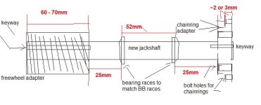
This is kind of approximate, because I've misplaced my good metal ruler, and the only one handy is on the edge of a plastic calculator: :roll:
jackshaft replacement 1m.PNG

I don't know how much longer the shaft has to be for whatever is going to hold the threaded part on the left side, and the chainring adapter on the right side.

The chainring adapter...I've been looking at all my chainrings and cranks; most are wierd non-standard ones, with totally custom spiders, many are swaged-on and riveted together. Some of all of those are not even 5 holes, some are 4 and one is 6.

Of the "normal" ones, the BCD's vary from 100/60, 110/70, 120/80, to 130 and 140. The double-numbers are for the two main rings first, and the smaller granny ring second. The others are just a couple of other chainrings I have that use 5 bolt holes.

I don't know if it is too much to ask, but if the ring adapter is made to be easily removable, could you make one for each of those sizes? The 110/70 and 120/80 are probably more important, since those are generally the larger ones (48T and up).

Although actually it would only take three, not five, since you could offset one set of holes from the other, to combine two close sizes into one adapter:
2-bcd adapter.PNG
Pardon the really crappy drawing. :) It might not leave enough material to be strong enough; I don't know. It also might not work with some chainrings that are formed/stamped/etc to "go around" the spider's ends. I'm not exactly sure.

On the ring adapter's thicknesses, well, it's whatever would make the right distance between rings for the typical triple-shifter. That seems to be 2-3mm; it's hard to measure it any closer than that. Maybe it's 2.5?

If I have to later on I can probably make more ring adapters out of aluminum on the lathe, assuming I can drill the bolt holes correctly (using a template, I'll probably get close enough).
 
I'm a little late chiming in here as you are well into this project, but do you remember the dual freewheel BB front sprocket system I made for a mtb? http://endless-sphere.com/forums/viewtopic.php?f=28&t=15529 I used a standard RH thread freewheel attached to the right crank with a single 44T sprocket as my main drive back to the 8-speed derailleur. I attached an ACS Southpaw (LH thread) sprocket to an adapter I had fabricated from a LH thread BB cone nut and a flange. The adapter is bolted to the left side of the 44T sprocket/freewheel assembly and the ACS sprocket threads onto the adapter. I bolted a 36T sprocket to the ACS for the motor to drive. Being LH thread, it tightens with motor rotation. I can pedal without turning the motor and under motor power the ACS freewheel engages to drive the the 44T and the chain back to the derailleur. The standard freewheel lets the cranks freewheel (remain still) while the motor drives the system. If you have the space you can bolt additional sprockets to the main drive one (44T in my case) so you could use the front derailleur as well. I've been riding it all spring and it seems to be running out well. I'm only running a 350W motor. Higher power might blow it all to pieces but the concept might work for you somehow - jd
 
ps I think SickBikeParts is making an extra wide 205mm BB square taper spindle that might have enough room for 3 crank sprockets (chainrings), the motor driven sprocket and 2 freewheels. I used the Cyclone wide spindle - jd
 
The only really hard part in using the existing BB shaft is that damn tapered square.

I do some blacksmithing, and the solution there is often: heat it up, and hit it harder

With that in mind, if I had to make something like this, I'd get a piece of shaft suitable for the freewheel holder, drill a hole in the end about the size of the square bit.

Heat it up, place over a BB shaft (scrap, not the good one!) in a vise, and beat the hell out of it. Pounding down will "swage" (fancy blacksmith term there) the hole out to square, and to a matching taper.

You may have to heat it a few times and beat on it. Don't let it cool on the taper, might lock on, but probably not.

Now, chuck it in a lathe, true it up, and cut threads.

That's what I'd do. But Thuds idea is much better. His idea is guaranteed to run true w/o wobble. My idea is not. Besides, he knows what he's doing, and if he says it will fit, it will.

Katou
 
katou said:
The only really hard part in using the existing BB shaft is that damn tapered square.
Yeah, that's one of the project-killer bits for me, but threading is the other (can't justify the cost of the taps and dies just for this thing, since if it doesn't work I couldn't then sell the adapters I'd originally thought of to make up for the cost, or use them on ebikes/trikes I have planned to someday sell).

Heat it up, place over a BB shaft (scrap, not the good one!) in a vise, and beat the hell out of it. Pounding down will "swage" (fancy blacksmith term there) the hole out to square, and to a matching taper.
That is something I never even thought of. 8) Since I was originally going to use aluminum for it, this might even have worked better there. (but I am pretty sure aluminum would just snap off past the BB shaft end once under stress from the motor under heavy loads).


jdcburg said:
I'm a little late chiming in here as you are well into this project, but do you remember the dual freewheel BB front sprocket system I made for a mtb? http://endless-sphere.com/forums/viewtopic.php?f=28&t=15529
I think I saw that in my searches before, but I can't use that method for a few reasons:
--My cranks are forward of the jackshaft, on a separate BB since it's a semi-recumbent
--I only have standard-threaded (not southpaw) freewheels, and can't go buying new parts for it partly because it's supposed to be made of recycled and used materials, and partly because I don't have the budget to justify buying something that I can use a different type of instead, that I already have. :)
--I need a very wide threaded area, so that I can experiment with different types of motors, cranks, and placements of freewheels on the jackshaft, to receive the separate chains from the pedals and the motor, and still line everything up.
--Mine is on the left side, not the right, complicating things further. (done primarily because I need the output of the jackshaft to directly feed the normal bike drivetrain).
--I need the regular triple on the drivetrain, so that the motor and the pedals can be shifted far downward for high torque for load pulling and/or hill climbing. (not a lot of hills around here, but they are doozies!).


I did start an attempt at making a crank freewheel using the BB-cup, but I realized while making the adapter ring for the chainring to freewheel that I would still be dealing with moving chain and that it would not solve the main problem I have been having, of chain derailing due to being pushed by motor rather than pulled by pedals, among other things. All it would solve is my feet going around with the motor even when I wasn't pedalling.

I'm only running a 350W motor. Higher power might blow it all to pieces but the concept might work for you somehow
It's a good thought, and I expect to break freewheels with it (I'll probably carry spares since they're small). I may well use the idea on a different bike that does not have a separate jackshaft, or that feeds the motor power in on the right side instead of the left.


jdcburg said:
ps I think SickBikeParts is making an extra wide 205mm BB square taper spindle that might have enough room for 3 crank sprockets (chainrings), the motor driven sprocket and 2 freewheels. I used the Cyclone wide spindle
If I had the budget for new parts, and didn't have the goal of recycling things for this project (well, really for all of them), I probably would. If I found used parts for cheap enough, I could still try it though. If not on CB2, maybe on the SierraTrek cargo longtail.
 
Amberwolf,

Do the freewheels have to be on the same side? The way I did one a couple of years ago was using a pair of cheap steel rear hubs. I cut them in half and welded the 2 halves with the threaded ends to make a dual threaded hub. Then epoxy on the threads of the left side freewheel made that one permanently installed.
 
Well, in that case, the best way to use some used materials, would be:

Used steel stock from Thud's basement! Seriously, let the guy help you out - if he's willing - it's for sure the way to go.

Especially if this is to be a one-off, not much benefit in being able to do it yourself. Even if you want to this more than once, if he makes the first one, you can take it to a machine-shop and ask them to replicate it.

Good luck however you go, but if you want results, fast, cheap, it doesn't get much better than what he's offering, JMHO.

Katou
 
OR get your mitts on a splined hub, and DIY broach a couple of freewheels to fit on it...OR just have at them with a file and probably get a pair finished and ready for the splined hub in about the same time it would take to get the grinding and welding equipment out and back put away afterward.
 
John in CR said:
Do the freewheels have to be on the same side?
In this case, yes, because all the power input is on the left side, and all the output on the right, so I can simplify the layout and still keep just a plain normal bike drivetrain on the right side.

John in CR said:
The way I did one a couple of years ago was using a pair of cheap steel rear hubs. I cut them in half and welded the 2 halves with the threaded ends to make a dual threaded hub. Then epoxy on the threads of the left side freewheel made that one permanently installed.
I have considered doing this for other parts of the project, and for other projects. But on this one that won't work.

John in CR said:
OR get your mitts on a splined hub, and DIY broach a couple of freewheels to fit on it...OR just have at them with a file and probably get a pair finished and ready for the splined hub in about the same time it would take to get the grinding and welding equipment out and back put away afterward.
I have a splined hub I could use. The problem then is to also get the bike's front triple chainrings on there, which would then have to go on the left end of the hub, and then I'd have to weld a frame and dropout piece up to the right of the existing BB to hold the whole hub assembly in place, so the derailer could still be used on the triple and the output of the triple would still line up with the rear cassette.


katou said:
Good luck however you go, but if you want results, fast, cheap, it doesn't get much better than what he's offering, JMHO.
Yes, nor is it as likely to break if he does it, which is why I took him up on the offer. :) But any alternate solutions to the problem are still pursuable, and so discussion is still open. Anything I can completely build myself would be great, but so far my attempts at that haven't worked out so hot. :roll:

My best idea to date for doing this totally myself has been to take two BB cups and weld them end to end at the nut end, so the threads aren't continuous. Then weld in some filler plates on the "righthand" end. Then file the center hole square, checking centeredness on a BB spindle mounted in the lathe and filing more where needed till it is as centered as I can get. I'd be able to still mount the contraption on a BB spindle (though it might have to be a bought spindle, like a Cyclone type) and bolt it on. Extracting it off later would be a serious problem, unless my 3-jaw puller is strong enough to do it. :)

But it would not give much if any horizontal position adjustment, and locking the freewheels on would require loctiting the retainer rings on (to the left of each freewheel).

Using a single continuously-threaded piece, as in my original idea or the one Thud can make, would let me horizontally adjust the freewheels to line up for different motors/etc, and would only require one loctited retainer ring (or two rings locked against each other, which is what is planned) at the left end. Simple spacer rings between the freewheels would keep them in the right alignment.


If I could do it, I would actually prefer to put all the chains for everything on the right side. But to do that, it'd need an extra-long jackshaft there on the right, to give me the clearances for this contraption to stick out on the far right, with a regular bike triple setup on the inner right, so it can be shifted by a normal derailer. Having it all on the right side would theoretically help with bearing wear, because the bearings would have less loading--most of the pulling would be passed directly thru the shaft itself and not even reach the bearings, instead of also being torqued against the bike frame as the left side pulls forward on the shaft and the right side pulls rearward. The latter is probably a part of what causes the twisting that derails chains, but I can't see it happen no matter how I test for it--it's too small a deflection for me to see where it starts.


This particular part of CrazyBike2 has had more thought put into it than any other part of it, with far less acceptable or usable ideas per dead brain cell. :lol:
 
Amberwolf,
I am keeping in the spirit of "Crazybike" & only using re-pourpoused materials....I stole away for a moment tonight to make the main shaft for you. Here is a photo update:

This is an old steel rod that once hung a 15# counterweight on a very old stroke sander. (been in the scrap pile for 12 years minimum)
I cut a foot of the end:
P5090022.jpg


next we rough it out:
P5090023.jpg


cut the bearing race on it:
P5090024.jpg


rines & repeat:
P5090025.jpg


I need to fill the propane so I can use the forge to harden the shaft in the race area (Kasenite to the rescue!)
P2070083.jpg


I will turn the freewheel adapters tomorrow night, Still looking for a suitable Stock for the cog adapter on the right side.
I will add a keyway on the right side but I am afraid the addapter is too long for me to broach on my equipment. I will provide heafty set screws & let you dimple the shaft in final position. I find a 1-2mm deep where the grub screws bite will hold about anything.
Happy mothers day1
 
:) re-purposed stuff also is cheaper or free to use. :p I didn't think you'd have any time to work on it for a while. It would be nice to get it back on the road, though!

Now I'll have to work harder at getting some more singlespeed freewheels that aren't trashed already, and finish my chainring adapter plates. :)
 
I have a pile of old freewheels on a bunch of old bkes I have laying around. (i think i have a new freewheel removal tool inbound for niagra cycle too) If i can get them off the hubs I will throw them in the box when the time comes.
 
Thud said:
This is an old steel rod that once hung a 15# counterweight on a very old stroke sander. (been in the scrap pile for 12 years minimum)
That's what I call repurposing. :) And good to have a scrap pile at least that old; some people are forced to get rid of theirs periodically, or do stupid things like I did when I moved to this house, and dumped 90% of what I had. :( I still regret that.

rines & repeat:
That looks spiffy. :) I'd say that the full length of that ought to be just fine; if I ever have to do other wierd experiments I can always use any extra length to stick other stuff on.

I need to fill the propane so I can use the forge to harden the shaft in the race area (Kasenite to the rescue!)
Can a regular propane torch (not OA) be used to do that kind of thing, or is it likely to cause warping/etc due to uneven heating (assuming it can even get hot enough)?


I will turn the freewheel adapters tomorrow night, Still looking for a suitable Stock for the cog adapter on the right side.
I might even be able to make those from aluminum sheet bolted together if I have to, or if I end up needing a different BCD or bolt pattern (like for some of the 4-bolt rings I have seen, and have on one bike). But I doubt it would be as precise as whatever you make. :)

I will add a keyway on the right side but I am afraid the addapter is too long for me to broach on my equipment. I will provide heafty set screws & let you dimple the shaft in final position. I find a 1-2mm deep where the grub screws bite will hold about anything.
Grubs might (should?) work; I suppose if I have a problem I can dremel out a keyway on shaft and freewheel adapter later on. I've never tried just grubs on something with this torque (enough to pull the rear wheel out of the dropouts, bend stuff, etc).
 
Thud said:
I have a pile of old freewheels on a bunch of old bkes I have laying around. (i think i have a new freewheel removal tool inbound for niagra cycle too) If i can get them off the hubs I will throw them in the box when the time comes.
I can certainly use them if you're not going to. ;) But if you are planning on using them, don't worry--I can get them around here I just have to start looking for the little BMX bikes sith singlespeed fws at thrift stores and yard sales again. I just typically don't get them as there are very few parts I can easily use for my various projects, and I already have a few frames of that type that I havent' found lots of use for yet. I tend to pickup bikes with cassettes instead, because I can eventually use all the different sprockets off them, plus the freewheeling cores are generally interchangeable with others I'm actually using. And they'll have shifters, cables, better brakes, etc. :)

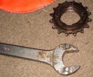
For a removal tool, you can DIY one like I did:
DIYFreewheelRemover.JPG
It's a wrench with two raised welds on the end, which were quenched to harden them a little, then filed and dremeled until they fit in the freewheel keyslots. Use the axle nut and a large thick fender washer to secure it loosely to the surface of the freewheel, grab rim, heavy mallet on end of wrench, and usually comes right off.

Last time I broke one of the welded bits off, but I just need to reweld it and refile it. I obviously didn't have it set to high enough current for that wrench's thickness. :roll:
 
Amberwolf,
After having one of thouse DUHH! moments. It occoured to me I can just make 2 freewheel adapters & broach them individually. That will make the whole set up more versetal during set up. For the right side I will provide a couple of hubs you can weld something to. sound good?
I am getting pretty lazy these days when it come to making special tools. (I am 99% done with the new cnc though :D )
I am spending more money to save time, time is becoming way more valuble than money to me these days.
 
Thud said:
After having one of thouse DUHH! moments. It occoured to me I can just make 2 freewheel adapters & broach them individually. That will make the whole set up more versetal during set up.
As long as the threads are continuous from one to the other so I can put either freewheel as far in or out as needed, including halfway onto each one if that's where it has to be to line up with the motors. Also so that when I thread freewheels on originally or as replacements or am changing chainrings on them, I can put them both on from the left side without taking anything off except for lockrings, spacers, and freewheels.

So I guess you'd need to broach them first, then mount them on the axle with tight keys to hold them aligned, and then thread them so the threads are continuous. And mark them inner and outer so when taken off they can be put back on correctly. ;)

AFAICS, I'd basically still need them to be one continuous piece during actual use, for almost all of the configurations I will be testing. I can imagine some scenarios that would benefit from two distinct sections to the adapter, or wide spacing.

For the right side I will provide a couple of hubs you can weld something to. sound good?
Well, I'll be doing whatever I do on that side with a triple ring set, so if whatever goes on the right end doesn't already mount triple rings in the right spacing with those BCDs, I'll have to figure out how to make whatever part goes between the hubs you make and the rings, here on the lathe out of probably thick aluminum sheet scrap I have from ex-rack panels, and drill the bolt holes out to bolt the rings to.

What will the hubs look like and how big will they be, so I can start planning the adapters to fit on them?

Note that I can't weld rings to it partly because several of the ones I'll have to use are aluminum, and partly because I need to be able to change them easily as I either destroy them or as I change gearing decisions and/or experiment.

I am getting pretty lazy these days when it come to making special tools. (I am 99% done with the new cnc though :D )
I am spending more money to save time, time is becoming way more valuble than money to me these days.
Yeah, there are times that if I had that option, I'd be using it a lot. ;)
 
Thud, you have confirmed it again for me. You are the man.

If there's anyone I want to see back on the road, it's this dude.

You better get the rest of the parts now AW, I really want to see this thing running!!

Thud, how big is that lathe there? It looked pretty small - do you have a big one too?

Katou
 
Back
Top