Need advice on crank drive setup

mrderekcu

1 mW
Joined
Jun 30, 2012
Messages
18
I've been lurking these forums for a good 6 months ever since I wanted to start my e-bike project. Originally I wanted to motorize a mountain board, but I decided that it would be a poor option for commuting to school and I didn't want a car. So now I wanted to motorize my bike. I live in a pretty hilly area and decided a crank drive would be the best setup for me.

I wanted to save a bit of money and am using a Turnigy 250kv 63-54 motor, the gold one, along with a 6S 150A Hobbyking car esc. I will be using a two-stage reduction, taking that 6250 rpm and turning it into about 97ish rpm at the cranks through a 12-60 compounded with a 14-60 and finally a 16 to 48. The 48 tooth being the final one on the cranks. I already bought the freewheel equipment from sick bike parts. I have yet to mount the entire thing, but I wanted to know...

Has anyone else done a three-chainring setup at the cranks?

And is 90-100 rpm a good absolute TOP speed?

I don't see too many threads on crank-drive builds, only advice about general crank-drives. And I really wanted to know if that crank rpm is best for efficiency.

Thanks!
 
And is 90-100 rpm a good absolute TOP speed?

the answer is going to be subjective....What is your normal pedal cadance? & your MAX cadence?
I would gear it to just short of your max cadance so you can give the bike meaningfull assist with the cranks.

I set up a crank drive with a friend who was determined to have it spin 130 (against my advice) It was really worthless for adding any pedal input.
Once re-geard for 85 max....the bike became a Joy to ride & gained a lot of efficancy....it really makes you feel like superman on the pedals.
 
By calculating in reverse from my speed and gear ratios I found that 90 rpm was something i can do without over-exerting myself, but I wouldn't want to do it for anymore than 10min. I figured going a little higher than my top-end average would be a good range.

EDIT: Truly normal and when I'm not even thinking about it, 75-80. Also, I initially chose 90-100 for a 25-30mph top speed, but if its better to just go a little bit lower, then I'm all for it.
 
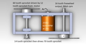
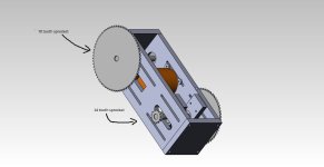
So i drew up a CAD model of the reduction system, still not exactly sure how I'm going to mount it because the downtube on my bike frame goes from a vertical oval, 0 to o to a horizontal oval, and thats just weird mounting for me.

Explanation.jpg

There is a visual representation of what I aim to do, the misaligned sprocket from the motor to the 60, I will fix by just flipping the sprocket 180. The motor is ridiculously close to hitting the inner wall, I may just do away with the extra motor mount, I also have a 63-54 without a skirt bearing I can use.

Left Side.jpg
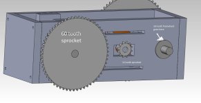
Labeled Right side.jpg

The gray washer looking thing is a flanged bearing.

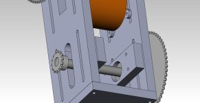
Adjustable Mount .jpg

The mount is adjustable for the motor as well as one shaft, this will allow me to account for any chain "stretch" along the way.

Any tips or comments are appreciated, and well needed to be honest :lol:
 
...still not exactly sure how I'm going to mount it because the downtube on my bike frame goes from a vertical oval, 0 to o to a horizontal oval, and thats just weird mounting for me...

There several tube clamps that can be purchased or made, with a circular center. To fill the space between the circular central hole in the clamp, and the odd-shaped frame cross-section: one option is to take a couple non-lubricated condoms, fill them with JB-Weld / Devcon, and place them in-between the clamp and frame, in the exact position you need them to be snugged up. After the epoxy has hardenend, dis-assemble and file away the excess epoxy.

As far as the circular-hole clamps, someone a while back made one and showed the method. I'll try to describe it. Take a block of aluminum that is undrilled / uncut, all squared..perhaps 1-inch by 5-inches by 4-inches. First drill the two parallel holes for the bolts. Either complete through-holes if you will use nuts (recommended) or...if the bolts will be threaded into the clamp, the initial holes need to be the diameter of thread minor diameter.

Drill the large central hole with a hole-saw on a drill. Then cut across the bolt holes through the center of the big hole (hacksaw?). At this point you are done if you are using bolts + nuts. If the aluminum is to be threaded, then tap one side, and drill out the holes on other side to the larger bolt-shank diameter. It would look similar to this hydraulic tube clamp:

images
 
Hah, now that's how you use an item for something other than its intended purpose! I will use that method, or some sort of variation in order to fill that gap.

Is the epoxy a reliable filler that won't crack? And since I'm peeling the plastic off of the epoxy, its just a properly shaped spacer, not bonded to anything right?

I definitely agree with you on the through-hole part, when I clamp this thing down, I want to do it as much as possible. I'm thinking of adding a plate to the bottom, drilling holes through the plate and mounting one half of the clamp to it. Then I can clamp as much as I want without worrying about stripping anything.

Whether I make my own or not just depends on how much a clamp costs bought vs built. And thanks for the help and the mount idea!!
 
I've been reading up on the topic of adding caps to escs. Every time someone adds capacitors, they seem to use ones that are nearly twice the input voltage.

The HK esc only uses 25V caps, good brand (Rubycon ZLH), but only 25 nonetheless.

My questions are:

Shouldn't I upgrade the caps to 50V versions?
And as long as I'm at it, how big of a capacity can I add?

Just want everything to run without the magic smoke comin' out!

Thanks!!
 
The closer you get to the voltage rating of you system (50V caps on a 48V battery), the specs are "slightly" better. The problem is that occasionally there are voltage spikes, so using a capacitor to suppress voltage ripple that is twice the system voltage is good design practice. the caps are about $2 each, so its better to just add more.

Personally I recommend the 50V caps for any system voltage of a nominal 36V or less. Some 44V LiPo / 48V LiFePO4 batteries are near 50V when fresh off the charger, so anything above 37V (10S LiPo / 36V everything else) I'd recommend using the 63V caps. The performance benefit of using the 50V cap over the 63V cap is VERY small, and is completely wiped out by just adding one more 63V cap than you had planned.

The danger is not in popping a couple of two-dollar 50V caps when you ride away with a freshly charged 44V-48V battery that is actually around 50V for a minute or so....the problem is when they pop and then the expensive ESC pops a half-second later.
 
I'm only running my system on 6S so it seems that the 50v rubycons will do the job. There's 3,000uf on the esc right now, do I need to up the cap of the caps lol?
 
I'm merely passing along what I was told by several of the electronics experts here. The uF (size) of the cap is unimportant to us for what we are using them for. I was told that a physically large cap (high uF number) is like a large water surge tank that has a small diameter pipe feeding it, and leading out of it. Electric bike with a lot of voltage ripple (voltage surges) can be happy using a small surge tank, as long as the pipes going in and out are large (resistance to amp-flow should be low. Low ESR = Low Equivalent-Series-Resistance).

Nobody makes exactly what I described, so we look for the available caps that are the closest to what would help us. Castle Creations ESCs have data logging so you can actually see how much help each capacitor provides as you add them to your system. For a crank-drive system using 6S (22V?), I'd use at least two 50V caps. The motor phase wires can be long, the wires between the battery and the ESC should be fat and short.

You should find some way to lock out power when the derailleur is in the top gears from a dead stop. OK to power them when you're rolling, but from a dead stop a high gear will be hard on the ESC. I don't know how to do that.
 
Oh, okay. I'll just replace the caps so the uF value is similar to what's there right now, and just up the voltage of each cap. I'll grab the 330uf 50V Nichicon PW series from Digikey and stack 3 per port and that'll get me to around the same capacity as before.

Just wondering, the caps in the picture looks like they're for the voltage spikes right?
View attachment 1

Really hope I don't screw things up somehow by taking those out and adding my own.
View attachment 1

I don't think there's a way for me to lock out the settings at the higher gear, at least one that won't cost me more money to make or skills to program. I'm only intending to use the motor after I start moving, so at all times, it will have to be legs first, then motor. Hopefully I don't get too carried away during the maiden ride.

Thanks again spinningmagnets, it helps to get advice specific to a project.
 

Attachments

  • photo 2.JPG
    photo 2.JPG
    91.2 KB · Views: 926
I don't think you need to swap any, perhaps just add two of the low-ESR caps. If you charge your LiPo to 4.1V per cell maximum (4.1V X 6 = 24.6V). you should be OK. http://endless-sphere.com/forums/viewtopic.php?f=30&t=22194&start=45

Here is the part number of a 50V cap that many here have used with success, it is guaranteed to be low-ESR.
http://www.digikey.com/product-detail/en/EEU-FM1H102/P12393-ND/613754
 
I already ordered caps, I looked at Nichicon's website before I did so and the PW series looked to be the best.

When I think about it though, I realized I was looking at the impedance not the esr, although are they not the same?

Anyways, here it is

http://www.digikey.com/scripts/DkSearch/dksus.dll?wt.z_header=search_go&lang=en&keywords=493-1908-ND&x=15&y=26&cur=USD

I planned on paralleling them, but if those don't seem capable of doing the job, I can just buy more since i got the Nichicon's through a friend's order
 
The impedance (resistance) is 90-mOhm and the ripple amp max capability is 1.03A

The caps you already ordered might be just fine, but the ones recommended to me by everyone here have a lower resistance of 16-mOhm (vs 90, lower is better) and a better amp-absorbing capability of 3.32A (vs 1.03A, more is better).
 
Well, I'd rather be safe than sorry. Those differences could possibly save my ESC. I'll just delegate the caps I already ordered to my R/C cars and planes.
 
I just tried the hall throttle to the servo tester mod. Resolution is actually pretty poor, but the bigger issue is that it's backwards.

When I turn the hall throttle, I noticed my test servo goes in the opposite direction than with the servo tester unmodded.

I hooked up the v+ and v- leads in the right place, the signal wire is linked to the middle pin of the board. And I can't recalibrate the throttle to work backwards either.
 
This looks like SolidWorks... Can you send me the assembly? Please! :D


mrderekcu said:
So i drew up a CAD model of the reduction system, still not exactly sure how I'm going to mount it because the downtube on my bike frame goes from a vertical oval, 0 to o to a horizontal oval, and thats just weird mounting for me.

View attachment 2

There is a visual representation of what I aim to do, the misaligned sprocket from the motor to the 60, I will fix by just flipping the sprocket 180. The motor is ridiculously close to hitting the inner wall, I may just do away with the extra motor mount, I also have a 63-54 without a skirt bearing I can use.


View attachment 1

The gray washer looking thing is a flanged bearing.

View attachment 3

The mount is adjustable for the motor as well as one shaft, this will allow me to account for any chain "stretch" along the way.

Any tips or comments are appreciated, and well needed to be honest :lol:
 
It's been a while since I posted as school has started for a month now. I finally got my aluminum and I need to send it over to get it machined. More importantly, I solved my problem with my servo tester and the hall effect throttle. Like i said before, not only was it backwards, it had horrible resolution and it would not work with my RC Car esc. The car esc needs a pulse from 1.5 to 2.0 to go forward, not 1.0 to 2.0 as many using the HV160 are used to. The solution was however, simple and cheap.

Arduinos!

I got an arduino from a friend to borrow and one in the mail for less than 15 bucks. I made a simple program to that uses the servo library and takes the hall effect input for control. However, the problem still existed with an odd resolution. I ended up using an inverse tan function (sigmoid) with some modification in order to get it to flow right. It's still not completely smooth, but it is a whole lot better. I also get the option of choosing my range (1.5-2.0) and I now have the ability to add switches to calibrate for the brake/neutral throttle range that the esc requires. I'll try to post up the code in case anybody wants it to play around with.

I'm especially happy because I now have a programmable system in case I need to add more inputs for other functions. And most importantly, its pretty cheap! 20 dollars less than a magura throttle and many more options for those of us trying to use car escs. (though, that may just be me :oops: )
 
Hi,

mrderekcu said:
I will be using a two-stage reduction, taking that 6250 rpm and turning it into about 97ish rpm at the cranks through a 12-60 compounded with a 14-60 and finally a 16 to 48. The 48 tooth being the final one on the cranks.
Thanks!
If you used 14t-60 for your primary reduction, compounded with a 12-60 your overall ratio's would be the same and it would be quieter.

Why not use a belt for your primary reduction?

What size chains do you plan on using?
 
I'm not sure what you mean by your first statement. Do you mean 250 rpm at the cranks?

Honestly, belts just seemed more of a hassle to set up properly, and they seemed insanely expensive. It is the better choice in terms of noise control, but pulleys looked like they would be 40 dollars each or around there. Will I regret it in the long run? Perhaps, but it's an experience I'm willing to go through for the sake of learning. :)

#25 chain, weak I know, but I was trying to save money. I can always switch em out if it comes to that, the #35 ones
 
Hi,
mrderekcu said:
I will be using a two-stage reduction, taking that 6250 rpm and turning it into about 97ish rpm at the cranks through a 12-60 compounded with a 14-60 and finally a 16 to 48. The 48 tooth being the final one on the cranks.
MitchJi said:
If you used 14t-60 for your primary reduction, compounded with a 12-60 your overall ratio's would be the same and it would be quieter.
mrderekcu said:
I'm not sure what you mean by your first statement. Do you mean 250 rpm at the cranks?
No. I meant that you are planning on using 12t-60t on your primary reduction and 14t-60t on your secondary reduction. The main combination of factors that increase chain noise are small sprockets combined with high rpm. So if you used 14t-60t on your primary reduction (bigger drive sprocket on your higher rpm primary) and 12t-60t on your secondary reduction you would have the same final ratio and a quieter system.

mrderekcu said:
#25 chain, weak I know, but I was trying to save money. I can always switch em out if it comes to that, the #35 ones
I think the #25 will be fine, but if not I'd switch to #219 (smaller pitch than #35):
Matt said:
You would be surprised how long that #25 chain lasts. My recumbent has over 1,000 miles on it with the same #25 chain. The PK Ripper has 500 miles of HARD abuse on it without any issues, no stretch, no tooth wear.

I just use light oil. I also neglect my recumbent chain because it is hard to get to. I lube it when the links start to bind. Even with that neglect, the chain is fine. Plus, this chain is so innexpensive, it is no biggie to replace it every couple years or so.

I run extra heavy-duty #25 chain from scooter parts.com. That chain is freaking DIRT CHEAP! I beat the crap out of that chain and in over 1,000 miles, have not worn one out, yet. But, it is so cheap, who cares!
 
Wow, i didnt even think about that. The main problem is that the 12 tooth sprocket was the only available one that would fit onto the motor. but I will see if i cant just switch them by using a properly milled spacer. I really appreciate that bit of advice. I just might buy another set of the drive sprockets just to see how much difference in noise there is.

And good to know #25 chain should last me for a while.

Thanks for the input Mitchji!
 
Hi,

http://chain-guide.com/basics/2-2-1-chordal-action.html
...You will find that the position in which the chain and the sprockets engage fluctuates, and the chain vibrates along with this fluctuation. Even with the same chain, if you increase the number of teeth in the sprockets (change to larger diameter), vibration will be reduced. Decrease the number of teeth in the sprockets and vibration will increase...
2.14.gif

Figure 2.14 Speed Variation Versus the Number of Sprocket Teeth
 
So its been more than two years since I've asked this question and bought all the gear. And it all just sat there while life went on.

This summer, I told myself I would finish what I started (and not let money spent just go to waste). And that's just what I did!

I built the gearbox I set out to, finished it about 3 months ago. Worse idea I've ever had.

kM6c2Iml.jpg


The thing was so thick, it was absurd. I couldn't believe I thought it was ever a viable idea. At its thickest point, it was 6-7in in between.

But I had half my aluminum plate left, and I went to redesign for the most compact drive with the parts I had on hand.

yz8CZrwl.png


And it came out pretty well all things considered.

After a few hours of putting everything together, it was assembled!

QCwUio9l.jpg


But of course, I ran into another problem. The torque from the freewheel to the crank was something that I could no longer hope to just ignore, ended up attaching a little plate to the downtube.

Here is V2 of my gearbox on my bike

oaKVDejl.jpg


Could be ridden, but not quite where I wanted it to be. Bike cyclist measured about 12mph max with the gearing I had. I never got around to measuring it, but I think the cadence is around 60rpm at the cranks. I suspect I'm not at that halfway point between rpm and torque and I'm losing some power as a result. I will gear it later to run for 80rpm at the cranks.

Took it back to my university and have been riding it around for the past three weeks. Low speed start was a problem between the low cadence and lack of hall sensors. If I gunned it too fast, the esc would lose sync and my heart sank each time. Finally added hall sensors today, and now I consider it V2.1

LfXqdCQl.jpg
The beauty that is the Lasercamm at our school

TQPz3ftl.jpg
Got a pretty good spacing in the end.

I'm pretty sure I burned out the esc a little during a hill run. Even with that distinct burnt smell we all know too well, it keeps on trucking. I wanted to ask if this is an actual thing, damaged esc thats not completely broken yet. As far as motors go, I understand that a motor works or it doesnt, just from the way its constructed. But an esc can have some mosfets damaged and still run yes?

Anyways, I just wanted to post this to show that everybody's help was not wasted. I did end up buying the capacitors that spinning magnets suggested when I bought my hall sensors.
On a flatish run, I got to about 25 + 2 mph using my phone as a speedometer.
-Pulled ~1000 watts at 24v and about 50 amps.

Chart for those interested
WW8W1SJ.jpg


If anyone has any advice about the esc, please let me know. I'm just being real careful for now.

Also can't stress this enough, thank you everybody for the help and the wealth of knowledge that lies within these forums!
 
Back
Top