Coaxial-BB-Jackshaft Middrive with TGY Rotomax 80cc Build

crossbreak

1 MW
Joined
Aug 2, 2011
Messages
2,884
Location
Germany
Hi guys,

since I was disappointed from my 900Watts converted Bafang middrive (as I was from my 500Watts TongXin :? ), I have decided to grip the duck by the balls and push 5kW+ into my second (non-commuting) bike, keeping it simple and go for a single speed setup, for the first time.

Edit: Even with 5kW, i'm still stuck with Middrives and will continues that :D But I keep the coaxial jackshaft!

I wanna use:
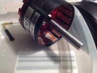
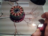
-80cc turnigy rotomax 193KV, terminated in WYE to get it down to 112KV, 80mm PC Fan for cooling (still on its way from china since weeks :?)
-420A 24S ESC from Alien Power Systems (didn't order yet)
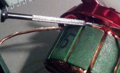
-20S/4p 74V/20ah Zippy Compact Lipos (on it's way)
-5amps BMSbattery charger
-2xSmartBMS from BMSbattery, beefed up using 4110 FETs (not modded yet)
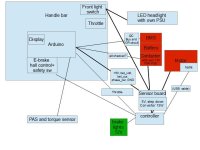
-Ardoino Nano V3 Throttle adapter/bike computer, to throttle phase current down to 200amps (selfmade)
- 20x4 characters LCD to display speed, amps, motor temp etc, no buttons or stuff, wanna keep it simple, firmware and daughter-board/ shield-PCB sketch will be posted here
-cheap $2 hall trottle
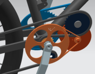
-2 stage reduction, using a BB-coaxial Jackshaft (or in better terms Jackhub), using 16/76T 8mm chain primay, 18/44T bicycle chain secondary, 11.6:1 reduction
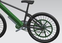
-centurion 26" 4-link fully frame, 100mm travel (front and rear), 26x2,1 tire inch front, 24x2,5 inch tire on the back wheel
-pedal setup: 53T front, 11-34T rear

What I wanna gain:
-Get up 30%hills without pedals Edit: 30degree hills
-35mph+
-good efficiency
-lightweight bike, will keep the huge batt in a huge backpack, I know that it will weight 10kg including BMS & shockproof housing :shock:

I'm still not sure weather I should use a bike or RC ESC. If the Alien doesn't do fine, I'll send it back. I have some modded 12FET KU123 controllers for testing, hope the 80CC wont melt it too soon.

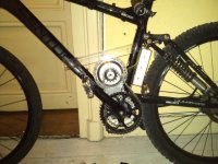
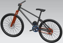
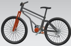
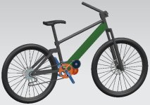
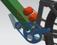
This is what it should look like in the end. My former bafang build shows where the motor should fit in (still the same frame), but the drive will be different, like shown in the CAD picture.

What are your opinions? anything I should change before I start?
This is build thread, not scientific, so I wont be in a snit if you guys fool around or post OT stuff this time ;)
 

Attachments

  • bafang_6.jpg
    bafang_6.jpg
    115.3 KB · Views: 5,660
  • first_try_jpg.jpg
    first_try_jpg.jpg
    49.2 KB · Views: 5,656
I will go for a 26" inch rear wheel, since with the 24" inch I can not reach 35mph without hassle. Still waiting on the specs about the Alien ESC from LFPwhich will hopefully be posted here http://endless-sphere.com/forums/viewtopic.php?f=2&t=44897&start=135#p685350 soon.

I recognized that mounting a rim brake to the rear wheel of this bike will be pain :?
 
here is my drive calc!

max speed isn't really simulated. But that is nonsense anyway on all high power single speeds, since they are always geared too slow. Did a rough estimation, in the end it will be faster.
 

Attachments

  • drvie_calc_110_70.xls
    15 KB · Views: 88
I would like to compare my build to whiplash new build. He is aiming for serious offroad performance. As he says, he needs gear shifting for durable torque output. IMO this is not necessary that's why I aim for a single speed. Of course I will run into issues here, which lets me think about a 2-speed drive.

To compare whiplash's drive train with mine, I made a chart, maybe it's not correct yet, since I dont have all necessary info about whiplashs drive yet.

From my calcs, the single speed would even beat whiplash's gear shifter MAC setup

Edit:[file deleted]
 
Got the info from whiplash, he'll use a 36/12 cassette and 12T sprocket. So here is the corrected comparison sheet. Now things look different, his setup gets slightly better hill climb :D
 

Attachments

  • drvie_calc_110_70_whiplash_MAC_comparison.xls
    16 KB · Views: 86
Interesting planning process. I eagerly await the part where you set up and upgrade the smart bms from bms battery. I just installed one and I don't know much about it yet. I only wish it had some lights.
I agree that two speeds would be ideal. Excessive shifting is tiring. I looked at the SRAM auto two speed it has very little range but it seems simple enough. No batteries it just shifts from first to second at 12mph. I only wonder when it downshifts.
 
thx for your comment. A 2-speed does not need a big spread, 150% is still better than nothing. But it has to stand 250Nm, no hub can stand this. The only way I see is using a dog clutch, just like thud does. A chain shifter would not be save IMO, not really satisfying :?
 
I set up this two speed on a pedal bicycle recently. Since the top and bottom deraileur stop screws work for alignment in all the gears (only two gears) it shifts perfectly with any lever, like a brake lever.
If I had unlimited time and money I would want a board that automatically shifts the deraileur using a solenoid and also tied to the throttle to let off the power during the shifts. ImageUploadedByTapatalk1358023770.798699.jpgImageUploadedByTapatalk1358023801.556959.jpg
 
Awesome! I will think further about this. But with this setup it's gonne be a middrive again, no chance to use recuperation

the smart bms will be hard to connect in series. Somehow both units have to talk. There will only be one cutoff for both. An OR circuit may solve this. The output of this is the main dsconnector. Maybe FETs are not the best solution here, automative people use large relais instead since they dont conduct if they fail
 
crossbreak said:
the smart bms will be hard to connect in series. Somehow both units have to talk. There will only be one cutoff for both. An OR circuit may solve this. The output of this is the main dsconnector. Maybe FETs are not the best solution here, automative people use large relais instead since they dont conduct if they fail
Yes the automakers high voltage packs like Prius always use a contractor with the bms not fets. They have a nice two contractor super safe circuit that has a precharge function and checks for various failure modes with both digital logic and simple analogue circuit paths before turning on. The contractor circuit also allows huge current during take off and regen with relatively cheap components. The contractors never switch under load so they use cheapies.
 
A forklift contactor would be a perfect fit. Like this Albright SW80B contactor, rated for 100amps @ 80Volts. Not cheap, but i guess it's worth the price: http://www.aliexpress.com/item/GENU...R-FORKLIFT-STACKER-PALLET-GOLF/624104114.html

There are versions with and without magnet blowouts, I guess they are made to blow away / disconnect the spark in short circuit condition :? This stuff really gets exciting, maybe we should open a new thread... i'll have a search in the sphere, maybe I find at least some references.

Edit: I did only find this site, maybe i did not search long enough :? http://www.evdrives.com/product_p/sol-sw180s.htm

Another issue is that wiki says that voltages over 60Volts are dangerous and need additional precautions. I could not use my favorite XT150 connectors, since they are not isolated enough. Maybe it's not so smart using more than 48Volts at the end of the day :? 4KW can still be handled @48Volts. It's only a hundred amps. It would not change much for my setup, I would just use 12s instead of 20s lipo and use the 80CC motor in Delta termination, just like it comes in stock condition :? BUT In DELTA termination motor induction is even lower than in STAR, and even in STAR it's a problem :AAARRGH: hard to decide :roll:

The main contactor would be also cheaper, there are plenty of 48Volts versions, but I still did not find one with magnetic blow outs :(
 
mr.electric said:
[...]
Yes the automakers high voltage packs like Prius always use a contractor with the bms not fets. They have a nice two contractor super safe circuit that has a precharge function and checks for various failure modes with both digital logic and simple analogue circuit paths before turning on. The contractor circuit also allows huge current during take off and regen with relatively cheap components. The contractors never switch under load so they use cheapies.

That would be something will also need. Ardoino will control it. Plz post more stuff about this, thx a lot :)
 
This is a first shot on the connections layout. Maybe it's not smart to use a single arduino. It may be better to use a separate one in the battery itself for the safety functions. IT has to disconnect the battery as fast as possible.

Thick lines use 74Volts, all thin lines are signals or below 20Volts.
 

Attachments

  • img0.jpg
    img0.jpg
    33.8 KB · Views: 5,340
crossbreak said:
Got the info from whiplash, he'll use a 36/12 cassette and 12T sprocket. So here is the corrected comparison sheet. Now things look different, his setup gets slightly better hill climb :D


Great numbers! I looked this over earlier but had the family out and about :)

I am amazed how much torque we both can produce in low gear!
 
I found a great explanation of the precharge relay control strategy on the Prius here:
http://www.eaa-phev.org/wiki/Prius_PHEV_TechInfo#System_Relays
I made a simplified version with Fechter once too. I'll look for the "72 v hobbyist " version of this circuit we came up with. It is designed to do some of these functions but does not require any computing power it is all analogue.
 
Ok here is the simplified version ImageUploadedByTapatalk1358053036.872311.jpg
This circuit operates as follows -
The ignition key enables the circuit, a button is held in to turn it on. A dash light illuminates when the system is on. Key off turns it off again.
 
Also I wonder about tying the precharge circuit to the bms output. Why rely on the limitations of fets for main battery power. A $5 relay could probably handle more power than $50 worth of fets.
 
Thanks for the circuit! Maybe one could add some sort of emergency LVC, if the battery voltage is too low =short circuit or something else, it will disconnect. I can imagine this can be done easily using a Schmitt-Trigger. A second arduino for safety is a bad solution, not as reliable and fast as an analogue circuit.

Didn't bother much about the SmartBMS yet. Did you try the IIC connection on this, mr.electric?

btw, I should add that I still have that middrive setup in mind, I once designed: http://endless-sphere.com/forums/viewtopic.php?f=28&t=45392&p=676522&hilit=phaser#p676147

the amount of custom parts is almost the same compared to my single speed design :?
 

Attachments

  • middrive.png
    middrive.png
    55.7 KB · Views: 4,784
this is what a battery box could look like, after sawing the downtube and inserting a box into the new free space. The box could be glued into the pipe stumps with the famous 3M epoxy. Of course the box must be much stiffer than the original downtupe and would also be glued to the saddle tube.
 

Attachments

  • battery_box_frame_2.jpg
    battery_box_frame_2.jpg
    45.9 KB · Views: 4,754
another approach would be to just swap the downtube for a 100mmx60x3mm extruded alloy profile. It would take eight 5,8ah 6s zippy compact packs, resulting in 1kWh of pure energy.

The new downtube itself would weight "only" 2kg. The major advance is that it's much easier for me to calc the strength of such a profile. I can imagine that only 2mm wall thickness would be needed, resulting in 33% weight reduction :D Collapse load isn't so important either, the real important thing is the bending strength (the second moment of area is important here) of the tube, which is far better than the original one, since it's more wide in both directions (still i'll calc and compare). The tensile strength is also better. What concerns me most is the connection to the tube stumps/headtube/bottom bracket.

Btw these profiles are available cheap with a tensile strength of 250MPa, thats almost as good as 6061T6 which has up to 300MPa

The whole downtube would add about 8.5kg including the 8 lipos to the bike.
 

Attachments

  • battery_tube_frame_1.jpg
    battery_tube_frame_1.jpg
    44.8 KB · Views: 4,769
some updates on batteries: I saw that normal Zippy 15C lipos get the same energy density as Zippy Compact, i'll definitely will go for them. I'll even get them before my already ordered Zippy Compacts, since they are available locally :D These 15C Zippy lipos almost got famous here, I know a few other guys here who use them with great success. http://www.hobbyking.com/hobbyking/store/__14384__ZIPPY_Flightmax_5000mAh_6S1P_15C_DE_Warehouse_.html

About the drive: Single speed sucks, it's just almost impossible to get a controller for the 80cc rotomax i'm willing to pay. I'll do some tests on the EMP N6364 with a cheap sensorless 12FET KU123 and 9Fet KU93. I've got a bunch of these, i like them. Only blew one FET ever on these, they are a really good bang for the buck. Seems to be the right choice for this motor. I started to redetermine a N6354 from 200KV DELTA to 116KV STAR, already got the 6 phase wires seperated. This wasn't easy on this motor since there was a bit epoxy on two of the wires. Additionally the front-end cannot be removed, which makes it hard to see where exactly the wires come from.

One magnet is damaged, that's strange since this motor has never run. Guess it's from the factory, looks like workers there got rid of some epoxy on the rotor, using a dremel :evil: Will got some finish on that against magnet corrosion.

Made a CAD pic for the dual N6364 middrive design.
N6463_2.png
 

Attachments

  • mot_2_damage_from factory.jpg
    mot_2_damage_from factory.jpg
    99.7 KB · Views: 4,727
  • mot_4.jpg
    mot_4.jpg
    127.6 KB · Views: 4,727
  • mot_5.jpg
    mot_5.jpg
    99.7 KB · Views: 4,727
left some space for motor mounted fans, mabye i'll be need. Also I got some space left to swap both motors for Rotomax 1.4 http://www.hobbyking.com/hobbyking/store/__17985__Turnigy_RotoMax_1_40_Brushless_Outrunner_Motor.html

uploaded a more detailed pic on how to seperate the phase wires for WYE or STAR termination
 

Attachments

  • N6463_3.png
    N6463_3.png
    23.5 KB · Views: 4,718
  • mot_3.jpg
    mot_3.jpg
    58.5 KB · Views: 4,716
Back
Top