Amberwolf's Bolt-Together Semi-Recumbent Cargo Bike

amberwolf

Administrator
Staff member
Joined
Aug 17, 2009
Messages
40,735
Location
Phoenix, AZ, USA, Earth, Sol, Local Bubble, Orion
file.php


The idea is not yet complete, but I was inspired to at least start physically putting stuff together after many weeks of trying to figure out what to do, when I knocked over a bunch of stuff in the back room trying to get the dogs out of there (they were playing around and not helping much...).

Anyhow, in picking it up and putting it away in a better order, I realized a few things that would fit together, starting with the Schwinn Sierra and Trek 930 frames I had gotten in the roadside find a few weeks back, I guess it was, plus a couple of rackmount cabinet rails.

Structural:
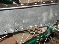
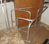
Basically, the rear wheel comes out of the Schwinn frame and goes into the rear triangle of the Trek frame. The Trek's headtube gets clamped to the seattube of the Schwinn, a bit above midway between stays. The rack rails screw into the accessory screwmounts on each triangle's dropouts, tying them together fairly stiffly (pretty much the same way I did it on CrazyBike2). Interestingly enough, not only do rackmount screws fit bike accessory mounts, the spacing between the mounts happens to line up perfectly with the rack screw holes, so I don't even have to drill new holes in them. :)

I will have to drill out some holes in the rails to clear a few things, and cut them to clear the cranks and whatnot; most likely I will cut just one rail in half and use it for both sides--it should be long enough to give me all the frame support and cargo pod mounting points I need.

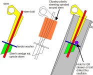
Hose clamps will not be sufficient for on-road operations, so I will end up using U-bolts most likely, to hold the headtube and seattube together. I may drill a hole in the toptube of the Trek lined up with the cross-bar of the Schwinn's seatstays to bolt them together there, too.

Theoretically it might be better to take the bearing races out of and cut the headtube of the Trek in half vertically, so I can clamp it around the seattube intead of just clamping up against it's backside. Doing that will change the positions of the dropout accessory points, so they might then require drilling holes in the rack rails. Oh well.

Seat:
The seat in the pictures is not what will be used, but it proved to me I can reach the pedals and can sit comfortably on it, reaching the handlebars in the seattube of the Schwinn, and that my knees will clear everything ok.

Steering:
For steering, the rear bars will be connected to the front by a tie rod (probably using skate bearings) just like i did for CrazyBike2, but this configuration will look more like Justin's cross-Canada bike's steering. I'll most likely leave the bars on there as mounting points for things like lights.

Motor:
Motor power will likely be provided by the Fusin front hubmotor, until I can come up with something more powerful to drive it thru the regular chain system, similar to CrazyBike2.

Drivetrain:
One difference is that I've got a rear hub and cassette in the Schwinn's dropouts, so I don't end up with either a long chainline, or a left-side pedal setup, and this means I can keep the pedal three chainrings shiftable, on the right.

There will be a chainring bolted to the hub itself on the righthand spoke flange, which is what the rear chain that goes to the rear wheel itself will mount to. The dropouts at the rear are barely big enough to hold a wheel at all, but the dropouts for the midhub are almost horizontal and can be used for chain length/tension adjustments if I use a single-speed setup at the rear.

I might leave the whole rear derailer and cassette on there, though, giving me even more gears if I need them for pedal-only helping using the front hubmotor, or gears specifically for the final motor/pedal drive stage once I add a motor into that drivetrain. Then I could put the motor input sprocket on the left spoke flange of the midhub, and that will give me a freewheel to keep pedals being driven by the motor (though it doesn't prevent pedalling from driving the motor).

A single speed would leave more symmetrical room at the rear, though, so I don't have to space out the rightside cargo pod/rail as I did on CrazyBike2 and would have to do on DayGlo Avenger if I ever put a rightside pod on it.

Suspension:
I will probably replace the front U-fork with a suspension fork, at least, after I change from hub to chain drive. Maybe before, if I use my steel fork off DGA or one of the others I have here is strong enough, or using torque arms if necessary.

More thoughts later, first some pics:
 

Attachments

  • DSC02556.JPG
    DSC02556.JPG
    98.9 KB · Views: 8,683
  • DSC02559.JPG
    DSC02559.JPG
    83.4 KB · Views: 8,683
  • DSC02560.JPG
    DSC02560.JPG
    52.5 KB · Views: 8,682
  • DSC02561.JPG
    DSC02561.JPG
    72.9 KB · Views: 8,694
  • DSC02562.JPG
    DSC02562.JPG
    84.6 KB · Views: 8,695
Nothing really new yet today; I'm coming down with *another* cold. :roll: More info about how stuff will work, though. :)

First, one major concept of this is to keep it all bolt-together, with no welding if possible. I want to see if I can do it, and I also want to create a cargo bike that people like Dogman without welders or leet welding skilzors can put together out of scrap stuff, or stuff bought cheaply at the hardware stores and such. Hopefully things that don't require one-of-a-kind finds as I have often used in the past. :)


Steering:
Since I don't want to modify either frame by welding to them, and really want to avoid modification of the Schwinn frame (it's a nice enough one I'd like to keep it intact for later use as just a bike should this one not work out as planned), it has been a challenge to come up with this part, especially.

One big issue is getting the steering stem for the bars to stay in the seat tube. For this, it turns out to be fairly easy in concept, though execution will have to be verified reliable later. ;) Using any regular stem of your choice, you remove the locking wedge nut at the bottom of the stem bolt, and reverse it so it's flat side is up. Between it and the stem a fender washer just small enough in outer diameter is inserted into the seat tube and large enough inside diameter to fit onto the bolt. It may require grinding down a larger washer, or boring out the center hole on a larger one, to find one that fits both the bolt and the seat tube as closely as possible without binding.

Then add locktite or similar to the wedge nut, and thread it on, flat side up, wedge point down (away from the stem and washer). That gives the washer a flat place to press against.

There are many sources for nylon or HDPE or similar types of slick plastic sheeting that won't disintegrate and bind under pressure, but a common one is those plastic sheet clipstrips you see in many stores. Often there are completely empty ones hanging on aisles in your favorite store, and they usually throw them away, so you can ask and get them for free. Most are totally flat with the product hooks just being notched out of it and pressed out to hang the product on. They can be reflattened just by pushing them back in. Alternatively they can be cut off if they are too bent up, as it doesn't have to be a continuous surface, just a fairly large surface area of flatness.

Tape one end of one of these to the stem, so that you can wind the length of it around the stem tightly, until you have increased the diameter of the stem to almost snugly (but not quite) fill the seat tube. You still need to be able to easily pivot the stem for steering. Cut the clipstrip at this point, and tape it down to the rest of itself. Use cellophane tape or similar, not duct tape, or else it will stick and bind after it comes off the plastic and warms up, and steering will be difficult.

Insert the stem assembly down into the seattube to test fit it. Should be an easy fit and freely rotate, but not rattle around in there. Needs to be tight enough to not wiggle but loose enough to steer easy. Once you have this, you can continue.

Mark on the stem where it comes out of the seattube top, then pull it out. Line up that mark with the top of the seattube, then mark on the seattube just at the top edge of that washer, just in front of or behind the bolt (whichever side does not have the point of the stem's wedge shape). Drill a hole all the way thru the seattube from left to right at that mark--you'll be putting a bolt (or quick release skewer) thru that to secure the stem from coming out of the tube. Insert the stem again, then bolt it in.


It should now be able to pivot freely at least enough to achieve full steering, although due to the point of the wedge on the stem itself will not be able to rotate 360 degrees (which is fine--the linkage bars to be installed won't allow that either). Now it is ready to have linkage bars to the front handlebar/stem created and installed, so that these rear bars will steer the front wheel remotely.
 

Attachments

  • SeatpostSteeringStem.PNG
    SeatpostSteeringStem.PNG
    48.4 KB · Views: 7,966
Thats a nice Schwinn Sierra with one of the first shimano sis index shifting! Great parts on those.
 
Yeah, it is a nicer bike than anything I have found like that so far. The tires were shot, and some of the plastic cable covers were sunrotted, and the cover of the left shifter is missing. Most of it, however, is in nice shape for it's age.

The Trek was once a nice bike, but it was a bunch of pieced together junk by the time I got it. ;) I still need to take apart the Manitou shock fork it had on it and see if I can fix it (since I'd like to use it eventually, perhaps on this new bike, though I think I'd have to change it's steering tube first).


The new bike they're being turned into is going to end up about a foot longer than CrazyBike2, partly due to the 26" wheels instead of 24", and partly due to both frames being longer than the CB2 frames. I'll also be riding higher than on CB2 by a few inches, but still easily able to reach the ground on either side while remaining seated.


Once I get the side rails setup, I will be able to make cargo trays or cargo pods that will detach for everyday riding. I have some folding aluminum cots I will modify into fold-down cargo rails a little like an Xtracycle's lower rails. Then any pods I want to use can be fastened to those, or I can simply tie down cargo to them.

I also have a couple of interesting cloth cases saved from when CompUSA shutdown three years ago. They were originally intended to carry a small ATX computer tower, keyboard, mouse, and software/books for their onsite training classes. (I guess they used monitors already at the sites). So they're fairly large, with at least as much space inside as my metal cargo pods, and they are suitcase style, but flexible, so they can carry cargo that does not necessarily fit within a rigid box of the same volume.

I'd have to use tiedowns to hold them in place, most likely parachute cord since I have a bunch of that. Disadvantage of using these instead of metal boxes is that I can't really lock them, since anyone could just cut the cords tying them to the bike to take them, or failing that just cut them open even if I locked the zippers together. But they're padded a little, and will hold groceries somewhat insulated (though being black they'll heat up lots faster than shiny metal ones would, meaning I may want to find a way to color them lighter--even gray would be better than black, so perhaps find something to wash some of the dye out).


Now I need to design and build a seat. I'd prefer something similar to CB2's, but more body-conforming. I have another of those bedside pottys that I used the tubing from for the first seat, so it will likely become the donor for the new one. I think I would like to bend the tubing though, to conform to me better.


I'll be making the seat so I can easily move it from this bike to the ARTOO trike, once I can get that design finished and built (which is a lot harder than this bike).


In the pic below, you can see the left side cargo pod of CB2 next to the cases; they should have around the same volume.
 

Attachments

  • DSC02565.JPG
    DSC02565.JPG
    57.5 KB · Views: 8,611
  • DSC02566.JPG
    DSC02566.JPG
    62.5 KB · Views: 7,937
  • DSC02567.JPG
    DSC02567.JPG
    60.5 KB · Views: 7,937
Those square-tube posts to the left of the aluminum cot frames are some steel retail-shelving aisle-signposts, saved from CompUSA's shutdown. They're about the same size and type as the rails on my CrazyBike2 that the pods are bolted to, except these are a bit thinner metal and are lighter. Probably not as strong, but the ones on CB2 are far stronger than they need to be anyway. :)

If I need the structural strength, I will probably use these the same way they are used on CB2, as top rails that the seat mounts across, and for the top part of the cargo-rail mountings. They have a mounting plate welded to one end already, too, which can be used to bolt my rear lighting to, and/or a trailer hitch.

These kinds of posts are fairly common in one form or another in retail stores, and they often throw them away when remodelling a store. Many stores have spare ones that never get used, and sometimes you can get them for free if you ask around. There are other interesting structural bits that get tossed out from promotional racks and signage from time to time at all retail stores, so keeping an eye on the various holiday racks they put up and then asking what they're going to do with the rack when holiday is over could net you some useful stuff.
 
I've basically gotten no further on this bike so far; just too much stuff happening. But I am about to restart on it.

I am first going to see about disc brakes for it, as a testbed for ideas to be used on ARTOO:
http://www.endless-sphere.com/forums/viewtopic.php?p=261351#p261351
file.php


I'll test the adapter idea using some sheet aluminum scrap I have (old rack panels and such) by making some rings to bolt to these two aluminum hubs, which are just regular bike hubs off the Schwinn Sierra.
file.php

file.php

I may instead use some older 10-speed steel hubs that already have ellipsoid holes in them from the factory, so I am not drilling thru these. In either case, I'll just drill the six rotor holes all the way thru the aluminum scrap and then the hubs, using the rotor's existing mounting holes as guides. Then bolt the rotors, rings, and hubs together and see how they hold up.

Of course, I'll have to weld on some caliper-mounting points first, and I'll use an old 10-speed fork for that rather than the nicer-looking Schwinn Sierra fork. For the rear, I'll weld to the Trek frame (that is the rear part of the cargo bike the Sierra is becoming part of). Then I'll know if the ideas are sound enough to use on the trike, or if I'll have to use the 3-speed hubs outside of the wheels, and use regular disc brake hubs on the wheels themselves.
 
Gotta watch out with radiator hose clamps. They've failed to hold up for me in a lot of cases. I originally had attached a 90 tooth #25 sprocket by piggyback over the outer chain ring on my present e-bike with them, but they broke and I had to ride home the rest of the way under pedal power.
 
It seems to depend on how they're used, and which directions the forces act on them. Also what they're made of and how. Typically as long as they're good quality to start with, and what they are clamped around is round (at least at the point the screw section is at) and about the same radius as the curve of that metal plate under the screw, they seem to hold up fine.

So for instance, securing almost anything to a bike frame with them works well enough, as long as that screw section ends up around the tube.

The bike itself won't be held together with the hose clamps like that when it's finalized--it's just so I can figure out geometries and such. I'll most likely use U-bolts at that headstock/seattube point, and I'm nearly certain that I am going to cut the headtube in half, and clamp the seattube within the headtube for extra no-movey-shifty-roundy-badtime power. :)
 
Well-said about the hose clamps. Mine had failed at the corners where the edges of the sprocket were. Afterward, I switched over to three strands of rebar tie wire twisted as one wire. That way has given no problems. :)
 
Wow it's been a while since I could do anything with this. Did a little more pondering with it today, trying to figure out suspension and stuff, and made some accidental discoveries along the way.

I kinda have a huge mess in the back room right now, trying to sort stuff out and digging thru boxes for parts, so it's hard to clearly see the bike in the pics. Sorry about that.

Ths is the frame from the front oblique left, with the front fork at the right end of the pic, and the rear triangle at the far left.
DSC02977.JPG
The front fork is a crappy cheap steel suspension fork from a Magna 26". It is so crappy that without a wheel in it, if I grab both fork legs one in each hand, and twist gently, I can actually rotate both fork legs and watch the brake studs and the arch they're on twist. :roll: But it is the only unused 1" stem suspension fork for 26" wheels that I have. The other 1" one is on CrazyBike2 and is a 24". The other steel one is 1-1/8" and is on DayGlo Avenger. The Skareb is aluminum, 1-1/8", as is the one on the cracked-frame aluminum Specialized bike. Since I want to use a front hub on this bike for now (probably the 9C), I'd really rather use a steel fork.

This plan would use the 24" rear triangle from ReCycle, probably modified for use with a 26" wheel, as a rear shock-absorbing pivot frame. It's most likely that I would use the rear dropouts on the trek frame to hold the crankshaft bolts of the rear triangle, as the pivot point.

That Skareb pneumatic/hydraulic shock fork that was on the Trek originally could be used as the rear shock on this, with it's adustable-pressure air valve (standard Schrader) left available to be used to adjust it to the pressure needed to compensate for whatever cargo I am carrying, if any. :)
DSC02978.JPG
I'd just need to build a pivoting mount for the former steering tube end on the back of the Trek frame, probably bolted to the brake studs and/or the seat tube. Then a couple of bolts welded to the sides of the orange rear triangle, with brass bushings over them for the dropouts of the fork to bolt to and pivot on.
DSC02979.JPG
The major disadvantage of the bike with this added rear triangle is that it is something like 10 feet long that way. :( But it all so far still just bolts together, no welding, so theoretically anyone can duplicate it. :)

For a seat, I've been trying to see what I could do that doesnt' require much if anything in the way of tools to make, welding or powertools, etc. I found a nearly perfect seat base in the stuff I already had; just don't think I ever thought of it that way before:
DSC02981.JPG
It's the skateboard I used some fo the bearings from for CrazyBike2's remote steering tie rod. More of those bearings would be used for the tie rod on this bike, too. I'd be taking the whole wheel trolleys off, leaving just the board, and probably would water-soak the board at one end (probably for days) so that I can bend it into more of a recumbent-style seat. But I might just leave it flat like that, and make a bolt-on seat-back, with a rear support rod, so that I can use the rest of the board as a rear rack.

You can see the handlebars I'd like to use, identical to those on CrazyBike2. They're just sitting in the front bike's seatpost right now, but I accidentally found another way to mount them than my previous plastic-wrapped stem idea:
DSC02982.JPG
I was just moving the whole mess out fo the way so I could clean up the room enough to feed the dogs, when I passed the steering tube of the Sierra's original fork very near the top of the Sierra's seattube, and realized it would be a nearly perfect fit. I just dropped it into the seattube for this pic. That means any other 1" steering tube would also work, and I have a number of those on kids' bikes that I collected as parts sources. Once the steering tube is clamped to the handlebars either by a quill bolt style stem or by a clamp-on style stem (I have some of each), then the tube can go down into the seattube, with a little axle grease smeared inside, and a short length of some other tubing just sitting under it inside the seattube to keep ti from going quite all the way down in.

I can make a retaining wire that loops up from the seatpost clamp over the bars and stem to prevent it from being pulled out. In addition, if I use a QR seatpost clamp skewer, I can tighten down the clamp to prevent any steering movement when the bike is parked, making it much easier to load and unload, along with a locking brake lever (which will probably come from DGA if I don't just modify one of the regular ones I have for that).

That means I don't have to drill any holes in the Sierra frame, unlike in my previous steering ideas, to retain the bars/stem within the seattube. I don't want to modify the Sierra frame at all if I can avoid it. If I had a different frame suitable for this project that was as strong and light as the Sierra, I'd use it but this is the only one right now. This will already be a very heavy bike, perhaps as much as CrazyBike2, with all the suspension and stuff on it. I had hoped to make a lighter one. :(


It is highly likely that I will first test out the whole Skareb-suspension-fork idea using just the Trek frame and a regular seat, along with the Specialized shock fork and a normal front wheel (since the Trek frame's headtube is 1-1/8"). That way I can find out if it is workable without also dealing with all the other chainline mess I'll need to work around on the much longer Trek+Sierra bike, or any other details.

If it works right, I may see if I can make whatever adapter I use on the Trek frame on my DayGlo Avenger frame, and try out rear suspension on that one, to see how it works with heavy loads. If it still works there, then I will likely proceed with this bike something like it's planned above.
 
OK, new plan. Somethng like the last bit above.
DSC03006.JPG
26" front (bent rim fusin) and 24" rear (old broken wheel off CB2), Trek 26" frame, Specialized 29" shock fork, 24" rear triangle, skateboard platform as seat, Skareb shock fork as rear spring, cruiser bars in seattube, 9C/GM hub in frame.
DSC03007.JPG

Naturally, lots of the above stuff doesn't fit together right, but it gives the idea of what I am after. For one, the brake studs are in an unusable position on the 29" fork, relative to a 26" rim:
DSC03008.JPG
and if I use a hubmotor up there I can't use a disc brake. Actually, the allloy fork has no provision for disc anyway.

There's a slight possibility I could go crazy with it, and flip the brake arms upside down...then have them be *pushed together* from the outside, rather than pulled together from the inside, but I'm not sure I can devise something reliable to do that. If I could, then I can use the 26" front in this 29" wheel and still use it's rim brakes. :)

Since it's a 24" rear triangle, a 26" rear wheel won't fit in it properly. If I remove the caliper brakes currently on it, the wheel might fit with sufficient clearance below the brake mounting bar. But the studs on it are for 24", so unless I do something to "extend" the brake arms, the pads won't reach the rim from side-pull or other stud-mounted brakes.

However, since the triangle is steel, I *could* weld a disc-caliper mount on it. I have no rear hub that will take a disc, *but* I do have a front and a rear hub (both of which have one threaded side) from Karma that are identical in core diameter, and could be cut and welded together to make a rear hub that I can then use one of several thread-on disc adapters I have, along with one of the discs I have in sizes from 140mm to 180mm.

Now, that brings up another possibility--a wide wheel. I could take those two hubs, place them unthreaded end to unthreaded end, and weld them together just outside the bearing cups, with bearings pre-trapped inside (just not yet greased). Weld two axles together end to end so I'd have one long enough to reach thru the whole thing. Then lace them up to two separate rims, but cross-lacing them so that the spokes from each hub's "inner" flange go to the holes to the opposite rim, but the outer spoke flanges are laced to the rim on that hub. This might not work out, so might have to just lace them as two individual rims.

Anyway, if it were laced up to two rims on one extended dual hub, the wheel would be stronger *and* it would have two tires and two tubes to take the cargo load, and keep my worry load for a flat down. I haven't had them with the slime liners and slime, but if it does happen on the cargo bike with it loaded down, I'd have to unload it all to fix it. :( But really, it's just to spread the load between two rims and twice as many spokes, and give me more rear traction, too, because....

I'd like to run this with a middrive based on a 9C/GM motor from Icecube57, as a first test (eventually would like to go high enough voltage to run that treadmill motor properly):
DSC03009.JPG
There is *just* enough space with this thing sitting down low in the middle triangle and offset as far as possible to one side to get a sprocket and chain onto it. It'd be bolted via spacers directly to the side cover, as this was a front 9C case, and I have yet to find anyone with 9C rear covers they'd part with.
DSC03010.JPG
I also considered a belt drive, running directly on the hub's ring between the spoke flanges, but I doubt that I'd be lucky enough for that circumference to line up with any of the belts I already have, for a full circle of belt teeth. A chain drive would be stronger anyway, for the kind of loads I'm looking at pulling, probably, given the belts I have are used or older.

All I would have to do is weld up some dropouts to the stays, to bolt the motor to. Probably out of 1/4" plate steel, with clamping-style horizontal dropouts to negate the need for torque arms.

Then the chain would go to probably a jackshaft that combines the pedals and motor via freewheels, and runs back to the regular bike drivetrain.

I would probably weld on a pivot point plate for the rear shock triangle, so taht I can use the actual dropouts of the Trek frame for the jackshaft (which might end up being the one from CrazyBIke2 that Thud is making, depending on how successful this bike design works out to be).

I'd need to also make a plate for the shock fork to mount to on the Trek frame, and on the rear shock triangle, so that it can pivot at the ends to allow swivel and shock action.

I could fit the NiMH packs in here if I needed to:
DSC03011.JPG
but I'd rather use the 10 TS cells. More weight but LOTS more power and range.

Bike looks skinny still:
DSC03012.JPG
but that's without the cargo pods and stuff that would actually make it useful. I'm still thinking I'll use those folding cots to make fold-out cargo racks along with the fabric computer carriers that can also fold up, to make a bike that isn't as bulky looking as CrazyBIke2, and can fit in more places when not loaded up. It should also be shorter than CB2, by a little.

Unfortunately it won't be a no-weld bolt-together bike this way; there's just too many little things I can't reliably make without welding them on.

But it will still be semi-recumbent. That skateboard on top of the back end can be the seat. Not quite like you see there, but I can probably heat-bend the laminated board into a comfy shape for a seat. Then bolt it to rails I'll be bolting or welding from the Trek's front part of the downtube, across the seattube sides, and the seat stays, cantilevered out over the top of the shock triangle. Supports for these rails at the rear will be triangulated from the rear end of the rails down to the dropout area of the Trek frame, and X-ed across too, right in front of the max forward position of the seatpost of the shock triangle, for lateral stiffness.

The seat will bolt to those rails, and the cargo pods will hang from them too. So it has to be stiff. They will probably be 1.25" or 1.5" square tubing, whichever I have enough of.

The rear triangle would be cut about halfway down it's seatpost, and the seat stays moved down to that point, so that it will be much lower and not possibly be an issue with hitting the bottom of the seat or rails.

If there is too much bounciness with the shock fork as rear suspension, I have some long pneumatic assists for a rear cargo hatch off a car. They're not sufficient to be suspension, but they have a lot of drag in either direction pushing or pulling, and will help dampen the suspension. If I don't have to use them for that, I'm going to use the rose/heim joints at one end of each to make my steering tie rod, which runs from the handlebars in the Trek seattube up to the actual steering stem in the front fork.

I might not use the seat tube itself to hold the bars, but may weld on an old headset to the trek top tube via a bracket, to put the steering farther forward, dependng on how my leg position works out.

Sound crazy enough yet?

I'm considering using both motors; the little fusin for most riding, and the middrive 9C/GM for power riding or cargo hauling.

Maybe this bike minus all the cargo stuff will become the Death Race 2011 bike. :lol:
 
Basically. :) But a tad more powerful. :p

I might end up simply moving the four-pole brushed powerchair motor over from CB2, but I'd need to weld a mounting plate to the bottom of that triangle to do it. Plus, I would like to leave CB2 intact and usable, once I fix it, so I have multiple alternate rides for experimentation and comparison. And fun. :)
 
I never thought of using a front fork in that position, thats a clever option. When you hit an unexpected pothole you will LIKE having rear suspension! It seems to me that on a semi-recumbent, a rear suspension is more useful than a front suspension. Of course, both are great to have whenever possible.

In the semi-recumbent position, there is no stress on my hands or wrists. I am old, and when I rode a conventional posture on a mountain bike, there was some weight on my wrists (leaning forward), so hitting a bump without front suspension was very noticeable.

I used a BMX handlebar to get an 8" rise to have some adjustability by rotating it forwards and back (compared to the MTB straight handlebar). I reversed it so the handle-angle flares forward, and then added two of the cheap-style quill-stems as handles (from the landfill re-cycle pile). My handlebar shape is now similar to the Cruzbike.

Because I am leaning back and have also reversed the steering stem, there is some "tiller effect", but it swings above my knees so its not a problem, just takes some getting used to. If we didn't have horrible potholes and sidewalks here, I wouldn't have cared...

dennis-cruzbike-freerider.jpg


FSLBhandlebars.JPG
 
spinningmagnets said:
I never thought of using a front fork in that position, thats a clever option.

I wanted to do something similar once before, when I first began working with the concept of CrazyBike1.0, but I didn't have any other shock forks except the one for the front of CB1, and the one on DGA. Instead I tried other things like seatpost shocks, but of course the loading on that was so extreme it just compressed all the way.

If I were to use a regular spring/elastomer fork, it would not work, not in the arrangment it is in right now. I am only trying this one becuase it is pneumatic/hydraulic and can be pressurized to suit the load.

I am not even sure if this one will work unless I pressurize it so high that it is nearly stiff, but it is going to take some fab work to make mounts for it before I can find out. The problem is that of leverage, vs the straight-push of a wheel directly pushing up on the shock. If I were to put this shock fork on the rear in a vertical position so it pushes from the droputs to the seat back instead of the horizontal position it is in now, pushing from the top of the stays to the back of the front end's toptube, it'd have less leverage against it and not be multiplying the force against it.

I think.

I'm not totally sure how all this stuff works; I have read and looked at animations and stuff and I still don't grasp it well. I see how it works on stuff right in front of me, though, and that's what it looks like it does.

So...bottom line is I'll have to build it and try it out. If I can, I'll be building it so it pushes vertically from dropouts to seat back, rather than how I have it now, but it depends on how I build the seat and rails if they can take that.

In the semi-recumbent position, there is no stress on my hands or wrists. I am old, and when I rode a conventional posture on a mountain bike, there was some weight on my wrists (leaning forward), so hitting a bump without front suspension was very noticeable.

Yeah, it's a huge difference with the DGA vs CB2 posture and bars. It's why I want to emulate all the things I liked about CB2 if I can. :)

I used a BMX handlebar to get an 8" rise to have some adjustability by rotating it forwards and back (compared to the MTB straight handlebar). I reversed it so the handle-angle flares forward, and then added two of the cheap-style quill-stems as handles (from the landfill re-cycle pile). My handlebar shape is now similar to the Cruzbike.
Sounds a bit like what I would've had for OSS on the ReCycle, but didn't build and isntead went with USS. I didn't know about the bar-ends then so I cut and welded handlebars together to make it. :)

Because I am leaning back and have also reversed the steering stem, there is some "tiller effect", but it swings above my knees so its not a problem, just takes some getting used to. If we didn't have horrible potholes and sidewalks here, I wouldn't have cared...

Yes--if we had good roads, I would not be considering a new version of CB2 with rear suspension. For that matter, I would not even care for a front suspension, as it adds significant weight to the bike (a few pounds). I'd have a seatpost suspension and maybe something on the bars, and that's it. Much lighter because it doesn't have to hold the bike and cargo weight, just mine. The rear suspension complicates *everything* on the bike, because I have to run rails from front to back to cantilever the seat and cargo pods out with less support at the rear than otherwise.
 
Got another bike at Goodwill today; "Built in the USA" it says. Probably means they bolted all the parts onto the frame here. :lol:
DSC03021.JPG
It is actually a nice light Cromoly 4130 frame, and is even of a height I could mount and ride comfortably, unlike the Schwinn Sierra (which I really like if it just wasn't so tall!).
DSC03013.JPG
The stuff on it is of average to low quality, older Shimano SIS with plastic thumbshifters for an 18-speed.
DSC03019.JPG
DSC03023.JPG
Crankset is at least not a one-piece, but rather a swaged-on 3-ring to a square-taper crank/shaft (which has a plastic housing over it to look like a spider-style crank, rather like the Landrider a friend has).
View attachment 6
Brakes are V-brakes, so at least they have studs on the frame.
DSC03015.JPG
DSC03014.JPG
Rims are aluminum and don't appear to be bent or deformed, but are not trued right now. Steel hubs. Tires are rotted and probably so are the tubes; even the rim tape (rubber band style) is disintegrated and falling out of the tires.

Has a handlebar mounted bag and some useful bar-ends, though.
DSC03020.JPG
But it was $7.99, probably because of it's condition and the missing seat and post. That's cheaper than a lot of little kids' bikes tend to be, and since I mostly wanted it for the frame and the bar ends, the rest of it is a bonus.

Now I have to decide...which frame (if any) do I cut the rear triangle off of: This one or the Trek? I need a 26" with studs on it to modify for a shock triangle for the above bike, unless I go for disc brakes by welding together those two hubs.... I just hate cutting up frames that I can actually *ride*. :?

Oh, also, the friend that sent me the LED taillights on the kennel trailer and DGA, and the turn signals on DGA, sent me this today:
DSC03024.JPG
It's a Yamaha motorcycle tail/brake light, also LED. It'll probably go on this bike.
DSC03025.JPG
Now I'll need front and rear turn signals for this bike; not sure what I'll make them out of yet, since I prefer to leave CB2 and DGA intact if possible.

Oh, and I'll need a headlight. Hmm....I have some white LEDs Icecube57 sent; gotta try those out and see how bright they are, and see if I can make optics for them to make a beam to see by. Then I can use the scanner-transparency-adapter thing for a light to be seen with.
 
Ponderings, trying to decide which of the two frames to use for this bike:

The Eclipse frame looks much larger than the Trek frame, until I put them next to each other. Then I find there is little difference. The front triangle is around an inch longer and 2 to 4 inches taller (due to slope); in the pic the BB and seattube are not quite lined up (I used the rear dropout as the lineup point).
DSC03026.JPG
The rear triangle is nearly exactly the same size.
DSC03029.JPG
Eclipse headtube is longer and thus would fit the longer steering tube of the shock fork better, without the stack of bearing cups I had to use to even try the fork on the Trek frame.

Slightly larger triangles means more room for batteries and stuff there, and only increases the bike length by a couple of inches overall, but most of that length is the front triangle, which means it'd be sticking out farther in front where it is less useful rather than more in the center where I'd rather have the length. Now I'm nitpicking and would really have to build a custom frame from scratch to get what I *actually* want, but that's not the idea of this bike. :)

My scales are not sensitive enough to trust on such small weights, as it seems to vary each time I weigh small stuff, but they seem comparable in weight for the bare frame given the extra weight the derailer/chain/cranks give the Eclipse frame. I am not sure about strength. Because of a red-with-black-splotches wallbike I once got for scrap parts, I believe I am somehow biased that similar looking frames are weaker just because of that, even though I know better, because the Trek frame "looks" stronger to me. I have no objective test though.

The Eclipse frame has no info about it's construction that I can find on it or the web (there are many mentions of Eclipse bikes but all are talking about some high-end bikes, and this is absolutely not one of those, unless someone took all the high end stuff of one of those frames and put basic stuff on it, long ago). It does say it's 4130 chromoly, but that's all. It's a obviously a welded frame, and doesn't seem like a spectacular job on some places, like the U-fork which has a few "eaten" areas where the weld puddle didn't fill after burning off. Fork could be made by a totally different company, of course.

The Trek frame also is 4130 chromoly, and also states it is "triple butted construction", and some other stuff I forgot already in the 30 seconds it took to get back to the keyboard. :roll:

The Eclipse frame is bright red, certainly more visible than the darker purple and green Trek frame, without any change to paintjob by me.

The Eclipse is fairly evidently a cheap road bike based on everything attached to the frame, while the Trek appears to have been designed as a mid-low MTB (it's hard to tell since I never saw it in it's original configuration, only in the obviously-pieced-together state I got it in). I suspect that means the Trek will have less frame flex, but have no actual evidence for this. I can't flex either frame by hand (other than being able to very slightly compress or expand the rear dropouts) but that means little.

A bit of searching finds that this color scheme was probably only used in 1994, and some people claim that frame is better than ones that came after. A few posts that describe accessories include the Shimano STX rapidfire shifter/brakelever combos this had, as well as the same derailer/cranks/chainrings.


Ahhrrrrggghhhh. The Trek frame is uglier; I'll just go with that as the deciding factor and keep it on there. :)
 
Drivetrain ponderings by my exhausted brain at lunch today. This is just the drivetrain, doesn't show any of the rest of the bike:
drivetrain1a.JPG
Basically, like the notes say, it has two power sources feeding the rear wheel. The 9C (or whatever) feeds the left spoke flange of the freehub, while the right flange feeds the rear wheel. The pedals drive a normal bike drivetrain in that it's a Biopace triple driving the 7speed cassette on the freehub witha normal derailer/etc.

The freehub bolts into the dropouts of the front rear triangle (confused yet?), which also means that I have to fabricate a mount point for the rear suspension triangle to attach to the front rear triangle. That mount will need to not interfere with the drivetrain.

I'd rather a pivot that clamps around the freehub itself, but I do not think I can fabricate something like that. If I could, it would mean the chain runs around the pivot point and I wouldn't have any growth problems. Maybe I will think of something. (well, something I can *fabricate*, because I can think of a lot of ways to do it if I had a machine shop and unlimited materials. :lol:)

Then a 3speed hub in the rear wheel itself, so that I can still have a high-medium-low gear for the motor, and also be able to shift that much more for the regular bike drivetrain. Basically I'd have 3 speeds for the motor, and theoretically 63 speeds for the pedals (although I think a lot of those are duplicate ratios or really close).

I don't know if the rear hub will survive this, but it will be a good test of the theory before I try to do it on the trike with two wheels running like that (in front). :)

Because it is in theory easy to do, I'm also going to stick a hubmotor in the front wheel, probably the Fusin geared motor originally on DayGlo Avenger mkII. This gives me a fairly light optional drive motor that also lets me get home if my crazy contraption disintegrates on me, as long as the rear wheel will still roll. :)

In theory it can also be used to help me start from a stop, reducing some strain on the 3speed hub, if I am heavily loaded with cargo.

I don't yet know what ratio I'll use on the hub motor's leftside sprocket to the left side freehub, nor what I'll use from the freehub back to the 3speed.

There is little enough resistance with the hubmotor that I am not terribly worried about being forced to drive it with the pedals if I must pedal-only to get home sometime. It's nothing lke the resistance I get out of the powerchair motor/gearbox on the CrazyBIke2 drivetrain, which is nearly impossible to overcome from a stop (for me).


Unfortnately I'm left with no disc brake option if I do things this way, unless I leave the Fusin off. Or figure out an easy way to make the disc adapter to the 3speed hub; theoretically it could be CNCd but I'd have to CAD up a file for that, and I am pretty uncertain of my measuring accuracy when it comes down to details like what I'd need on this thing, and doubt I could make something that would end up with a working adapter. I'd be better off hand-grinding/filing such a thing if I can find the right piece(s) of material to make it from.


Well, I'll burn that bridge when I get there. ;)
 
Started actually making sure I have all the parts to stick on this, and began bolting on some stuff I know for sure I'll use, like the Biopace cranks onto the Trek's BB, and the 7-speed freehub into the Trek's rear dropouts. That will make the pedal section of the drivetrain, and the jackshaft for combining motor and pedal power.


Since I basically can't use the Specialized forks because the brake bosses/studs are in the wrong place to work with a 26" wheel, and I really don't want to use a larger front than that, I took a look at all the forks I have...and I have none of the 1-1/8" steerer tube style ones except the Specialized and the Manitou (which will be the rear shocks on this bike). So I'm going to have to make an adapter ring for the bearing race of a 1" tube/fork to be affixed into the larger Trek head tube. Shouldn't be that hard, but it's one more thing to do.

As for forks, I've only got a couple of shock forks besides those two (and the one in use on DGA). One of them is a 24" on CB2, and the other is the 26" cheapie in the pics on the previous page. It works, but it is definitely not the greatest. Better than not having one I suppose. At least it has steel dropouts for the hub (fusin, probably).

I am sorting thru my assortment of steel bits for the tubing and plate I will need to make various parts. I may not have enough 1/4" steel plate, or the 1" square tubing I'd like to use for the seat/cargopod rails (as I did with CB2). Have to look around for more stuff with 1/4" plate in it to collect again. Might be able to use the rack rails (see first pics in thread) to do the seat/pod rails, as long as I have sufficient cross bracing and I ensure the rear triangulation of it is sturdy.

Maybe more later but I keep dozing off typing this. :(
 
You pretty much are a genius when it comes to kludging together reclaimed parts of all kinds amberwolf...I swear there's no part that won't work for you somehow when you're building a bike! Very cool, can't wait to see it "operational" since I also will note most of your bikes never are really "done" lol. Hell most of ours aren't, I know mine still isn't! :p
 
I dunno...I still think most people could do what I have done if they had the motivation for it like I do. ;) Then again, I'm more stubborner than most, I guess. :lol:

As for being "done", you're right about that. The only projects I ever have that are "done" are things I don't use anymore. :lol:

I wish I could stay awake long enough to accomplish something for myself, when I am not busy doing something for someone else. Maybe if I had a month's paid vacation (not going to happen) I could rest up for a week and then start working on stuff. :)

That said, I went digging in my stuff again and discovered I have misplaced the threaded hubs that Karma sent me, that I was going to splice together to make myself a rear hub I could put a disc *and* a freewheel on. I guess it got miffed that I was thinking about the 3speed hub instead, and ran away. :(

I still have the front disc hub Papa sent, which is destined for CrazyBike2 if I can find a set of spokes and a rim in my wheel stuff that will actually lace it up into a 24" wheel. No threads on the other end of it to use as a rear, though, and nothing I can easily splice it with to make it into one. Still pondering that, though.

Also pondering ways to make the disc adapter for the left side of a 3speed hub. Lots of ideas, but no certainty any will work till I try them. The easiest way is probably not possible, which is to just weld the dang disc to the hub; it'd probably vaporize the grease inside, or worse turn it into gooey ick that jams up the gearing. Plus I'd probably weld it on slightly wobbly and be unable to use it as a brake. :lol:

I wish I could take the frame and parts to a fast food place and just sit there for a few hours pondering and drawing. At least there would not be any real distractions, and I could probably accomplish something. With the BOGO coupons some of them put in the local mailers, it's cheap enough to go (since I'd have at least two meals out of what I'd get there). But I'd have to settle for the laptop with lots of pics of it all at different angles, since I don't think they'd be happy with me spreading bike parts all over their table. :lol: :oops: I guess I could do this if I have enough time in one stretch....someday soon, I hope.
 
ive been watching this build to see your rear triangle bolt up.and at least ya made me laugh,i pictured a bunch of bicycle frames and parts in a fast food joint and kids goin crazy grabbin everything,haha.i can just see it. :lol:
 
Yeah, I can just imagine that happenig.. :)

The rear bolt up is uncertain at the moment, since I am definitely not going to use the dropouts for it--I want to keep the whole drivetrain in-place and easy to deal with as original, for the pedal part. Partly this is simply so that if all else fails, I can take the rear wheel and stick it in place of the bare hub, and pedal home on that. Not a likely situation but stranger things have happened already.

I am probably going to add the mounting points for the rear pivot as part of the frame that will hold the seat and cargo pods. That'll be a triangle extending up and back.
structure1.PNG
Green is the Trek frame, orange is the (modified) rear triangle. Dark gray is the stuff I need to build out of square tubing (horizontal rail) and small diameter round tubing (vertical and angled bits). Also dark gray are the plates I'll need to build up for mounting the rear pivot. I forgot to add the disc brake mount points but I might not be able to use those anyway.

Light gray is the front and rear shocks. Mounted vertically, the rear shock will work just like it did as a front shock, and will pull up on the whole rear load, instead of the rear load just cantilevering out into space and breaking off on some giant pothole. :lol:

Seat, tires, bars, tierod, chainlines, etc are all black. Motor chainline is not shown, as I am not yet sure which motor will be used.

But dang, this thing ought to have a lot of frame space for "stuff" when i'm done. :) I just hope it isn't as heavy as CrazyBike2. Well, it won't have to have SLA powering it, so that ought to help. :lol: Hopefully all the battery will fit in the front and/or center triangles, leaving more capability to haul cargo in whatever rear side pods I make, without having to stiffen up the rear suspension to the point of rock hardness.
 
The Eclipse has now gone here:
http://www.endless-sphere.com/forums/viewtopic.php?f=2&t=20595
as The Velcro Eclipse, a spare "normal" ebike, to be mutated later as the need arises.


Today I got ambitious enough to go out in the afternoon heat (only 105F) and start cutting metal and experimenting with various frame configurations to see how I can arrange all the pivot-point area bits to keep them from clashing, and still end up with a strong join.

As usual, just ignore all the dog-chewed fragments of debris in the pics... :roll:

A damaged BMX frame that I already used some seatstay bits from to fix my mistake on the CrazyBIke2 frame (where I crushed the seat stay near the dropout trying out one of the dumber suspension ideas) donated it's rear dropouts:
DSC03096.JPG
Mostly because they're large and slotted, which will allow me to modify them as needed to fit the Trek frame wherever I find they must go. Left all the stay tubing on them I could and still be symmetrical based on the shortest existing length of stay. When I attach them, I'll be fishmouthing out the stay tube ends so they can be welded over the curve of the Trek stays.

First configuration, with the motor/pedal power combiner jackshaft (a rear hub) in the Trek dropouts, so that it can still be used with the pedal-side gearshifting.
View attachment 6
Doing it this way will definitely allow all the pedal-side stuff to clear the pivot and operate as it would have as just a rear wheel drivetrain.
DSC03098.JPG
But the chain from the jackshaft to the rear wheel would probably need a guide around the shock triangle's chainstay when it's pivoted up during bump.

Next, the pivot point as the actual Trek dropouts, and the BMX dropouts used to hold the jackshaft.
DSC03100.JPG
This would allow full clearance of the wheel chain at all droop-to-bump positions, but would require a guide around the pivot point for the chain on the pedals, which would prevent a derailer from actually working. In theory I could mount a derailer to the BMX dropouts , but not the same kind I have there--it'd have to be one of the cheap ones that bolts under the axle nut instead. I don't like them as much.
DSC03101.JPG
Also, the shock triangle's seatpost would hit the jackshaft in bump if it were right there; it'd have to be moved quite a bit forward of that to work.

Now this one, or a variation that puts it under teh stays, might work better. Would still need derailer mounted to BMX droputs instead, but might avoid a guide roller/etc for either pedal or wheel chains.
DSC03102.JPG
DSC03103.JPG

I think keeping the pivot at the Trek dropouts is stronger; and I think the drivetrain will be complicated no matter which way I do it. :(

BTW, if you look closely at the first configuration pic, you'll see that the "nut" on teh pivot point visible is not a nut. it's a disc retainer from my Makita angle grinder (donated by JEB).
makita retainer.JPG
I dropped one of the real crank nuts in the house somewhere earlier, and haven't found it yet. Needing something to secure things together while I took pics, I just used the grinder retainer as I had it to hand with the grinder, as I had thougth I was going to fishmouth the parts now. (until I realized I needed to ponder som more first).

So if you find yourself short a crank nut, you may be able to use a Makita (or other) angle-grinder disc retainer nut to get your cranks onto the crankshaft. :) At least the Makita one is the same thread pitch and diameter, fits very snugly but not improperly.

Interesting coincidence that I had it in my hand at that moment to try it. (I wouldnt' have thougth to, otherwise).
 
While I was waiting for the all-store meeting to get started, I sketched up some frame ideas.

The first is basically the same as the last idea above, to be built from existing bike parts.
cargobike frame 1.JPG
Next is a simplification of it, lining up all the tubes, so that the frame should in theory be stronger, but would have to be completely custom built rather than using bike frames mostly as they are. It also uses a simple swingarm for the rear instead of a triangle, as that's all that's really needed, with the shock coming from the end of the swingarm up to the rear cargopod/seat supports.
View attachment 1

A possible variation of it would use curved side tubes and curved top-rear tubes, to create a seat frame that would be a sling to sit in, and also to create a kind of fairing shape I could cover with cloth or bottle plastic.
cargobike frame 3.JPG
 
Back
Top