5304 axle snapped after 5700 miles

NeilP

1 GW
Joined
Nov 27, 2010
Messages
5,012
Location
49.17303, -2.05354 Jersey, Europe
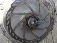
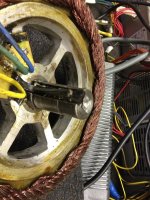
After almost 6000 miles and one year my axle finally gave out.
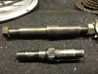
First picture is taken seconds after it snapped. I was just slowly pulling away in slow traffic from a stop. I stopped before I really even moved, I probably went forward 6-12 inches. Note that just one phase wire snapped, they did not spin

Tested controller and it is OK

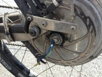
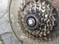
Very little evidence of old fracture, a slight section on the chain side , of about 1mm deep. that was not fully rusted. All the break surface was very fresh and bright
IMG_0255.jpg

IMG_0256.jpg

IMG_0257.jpg

IMG_0259.jpg

View attachment 1


Here is a test one I made many months ago as a trial. Still need to work out how to feed the wires through. Not sure if I should make anothe axle thicker still, and do a drilling rather than slot. Trouble wth that method is that then the wire exits the end of the axle and is more prone to damage. Since I am making it thicker and will need to re make torque assembly and dropouts, I suppose I could stretch the dropout area a bit, and make a second radial drilling to allow the wires out inside the dropout in a similar position to where they currently exit..
Worried about the size of hole to drill..do not want to go too big and weaken the new axle.
Think it will be 19 or 20 mm threaded portion...going big this time.

I think that if I split open the bundle of hall wires in to 5 individual cores, then the bundle of wire going into the hub can be smaller...the thinner hall wires will sit between the curves of the fatter phase wires, filling in the gaps


IMG_0263.jpg
 
In the search for a bearing that I could use to fit a larger shaft, I wondered about needle bearings.

What do you reckon on these?...just wondering about side loadings, these will not cope well with that

http://simplybearings.co.uk/shop/p555389/HK4012+Budget+Drawn+Cup+Type+Needle+Roller+Bearing+Open+End+Type+40x47x12mm/product_info.html

Maybe better sticking with a roller bearing, go slightly thinner in width...9mm in stead of 12mm it is a 6005on the brake side..which is 25x47x12

go with a 61906

which is 30x47x9mm

Could still leave the chain side as is, ..I do not plan to add cooling pipe like Luke, so i can still geta big enough axle through that side if I go with a 16 or 14 tooth minimum sprocket on that side..rather have 11 but that means a thinner axle again
 
If you're gonna use a larger bearing anyway, whynot just enlarge it so much that you can pass the phase wires between the axle and the ID of the bearing? Problematic on the chain side, but if you don't *require* the rear disc brake it would be easy on that side (assuming the cover thickness allows for it).

If you do need the disc, you could make an adapter plate to go from the motor cover to a modified rotor.

Alternately just make a whole new side cover with mount points for a modified rotor and the new bearing size support.
 
amberwolf said:
whynot just enlarge it so much that you can pass the phase wires between the axle and the ID of the bearing?

As it is at the moment you mean, just with a bigger slot..yes i had thought to do that,but like the idea of having the wiring completely inside the axle, in a bore. No chance at all of rubbing or chaffing like that

amberwolf said:
Problematic on the chain side, .
Chain side can stay as it is, and still take the bigger shaft...if i loose the 7 speed mega freewheel. Fit something with a 14 tooth freewheel, and you do not get that step down in diameter on the freewheel.

amberwolf said:
but if you don't *require* the rear disc brake it would be easy on that side (assuming the cover thickness allows for it).

even with the disk, it is fine. I can make the whole thing a bit wider and stretch the frame out a bit. I am going to remake the rear end anyway, so i can make it wider and weld it on to suit

amberwolf said:
If you do need the disc, you could make an adapter plate to go from the motor cover to a modified rotor.

Alternately just make a whole new side cover with mount points for a modified rotor and the new bearing size support.

Already got a series of thicknes adapter plates made for a different job...As for new side plate...that was a thought too.

The difficult bit is the splines for fitting back in the stator. I do not like the keyway idea, they are far more prone to work loose. Yes it can be done but then that will mean machining the stator too....nah..rather find the correct knurling tool and roll the splines back on my new shaft
 
NeilP said:
As it is at the moment you mean, just with a bigger slot..yes i had thought to do that,but like the idea of having the wiring completely inside the axle, in a bore. No chance at all of rubbing or chaffing like that
Nope, no slot at all--entirely between the OD of the axle and the ID of the bearing, witha "filler" ring to support the rest of the bearing/axle area. John in CR has posted some mods like this, and at least one manufacturer is making at least one model this way now (but I don't remember who).

But if you do this, the ID of the bearing and whatnot and the wire thickness will probably be larger than will fit inside a disc rotor mount. Dunno for sure, just guesstimating.


Running the wire inside the axle or slotting the axle furhter weakens it. It's bad enough that you have to make a step from the main axle size down to the dropout size with flats on it--that makes a stress riser that eventually can break--just like what happened to you already.
 
amberwolf said:
Nope, no slot at all--entirely between the OD of the axle and the ID of the bearing, witha "filler" ring to support the rest of the bearing/axle area. John in CR has posted some mods like this, and at least one manufacturer is making at least one model this way now (but I don't remember who).

Umm do not get it what you mena because that is how the current system works , the wire runs in side the bearing ID, and along the OD of the axle..well in a slot
But if you do this, the ID of the bearing and whatnot and the wire thickness will probably be larger than will fit inside a disc rotor mount. Dunno for sure, just guesstimating.


amberwolf said:
It's bad enough that you have to make a step from the main axle size down to the dropout size with flats on it--


but I am not...no step, well not down to a 14mm thread and flats like original size. I am making new totally home made dropout/combined torque plate. If I go with that bearing I listed earlier the 61906 which is 30x47x9mm, we will be looking at a much bigger axle and nut..24mm thread at least, maybe bigger ..even if brake side is bigger than other, no worries.

If I can bring the axle all the way out to the end to ...dunno,...28 mm...24.. whatever I can get . A 10mm bore down the centre of the that size will be much less reduced in strength. There is no way I am going back to 14mm. Even the trial axle I made before is not thick enough...seem to remember that was ....um.. 16 or 17mm OD threads,...
 
NeilP said:
Umm do not get it what you mena because that is how the current system works , the wire runs in side the bearing ID, and along the OD of the axle..well in a slot
I mean without the slot at all, as that slot weakens the axle (and adds manufacturing steps and labor). Without having to fit them in a slot, you can have any size phase wires you want, too. ;) Well, up to the size of the largest ID bearing you can fit in that space, anyway.


but I am not...no step, well not down to a 14mm thread and flats like original size. I am making new totally home made dropout/combined torque plate. If I go with that bearing I listed earlier the 61906 which is 30x47x9mm, we will be looking at a much bigger axle and nut..24mm thread at least, maybe bigger ..even if brake side is bigger than other, no worries.
Good-if you can make the axle stepless then you have a much stronger one. I've seen so many things break (mostly from my misuse of them vs their intended purposes) over the years that would not have if they didnt' have steps in diameter causing stress risers. :(

You *can* have a strong axle that also has smaller ends on it--if you taper it rather than step it. But even stronger is probably one that stays same thickness along entire length, including the threaded area for the axle nut, or whatever mounting method you will be using.
 
sorry to see your axle broke, a friend of mine showed me how to 'peen' the torque arm so that its a nice tight fit on the axle
(i'm sort of guessing if there was any slight movement in the torque arm hole relative to the axle) it might have contributed to the fracture).
You just bash around the hole on the torque arm with a hammer while torque arm is lying flat on an anvil or similar, and it allows to get a very snug fit
onto the axle, bashing around the hole shrinks the diameter of the hole by very small amounts as the metal gets slightly squashed or flattened, might be useful.
 
Cylte 5304 axles notoriously soft to start with, or at least the threads were anyway. And you run serious torque into one.

I keep expecting the same thing to happen on my dirt bike. One pinch dropout controlling torque, on the side with the wires coming out the axle. Quite suprising I haven't twisted it off yet slamming aound in the rocks, and pulling 2000w.
 
awesome pics. impressive snap.

i suppose it's too late for a refund :lol: , but seriously, someone at xlyte ought to see that. it was only drawing 500W, right? :lol: what's it pulling off the line, 8kw?

i wish they used the same axles as 9C's..
 
Ouch! Soft metal, heavy motor and you're doing serious regen, correct? That sure sucks and could take long enough to sort out that you'll be missing the bike. Be glad it happened when it did rather than full bore in a corner...
 
I got lucky ith Kenny from Xlyte

Well more precisely, we got unlucky and then luck came back again..had parcel sent from there with 8 pairs of hall connectors last month...it did not arrive, Kenny e-mailed me this morning after TNT contacted him. I said I had not received it and he said he woudl send agai. I asked them to stop and not send just yet, I wantyed to get another few meter of the thick almost 10 gauge phase wire they use.
I sent him pics of the axle, and he said that he could not supply new as, as we know, they are no longer in production, but he did have one he coudl send me from a reject motor. So he is sending it for free along with the rest of my bits.

So I will have a spare stock axle, as well as the one I am building up. If for any reason I am not happy with the new one I am machinging, I can use the stock again..well the last did last 6000 miles, so it is not too bad.

At start up at 100 volts I am seeing peak current draw of around 150 amps..so 15kW..but as we know not all of tha makes it to the rear end.

I have been working with some 30mm bar this morning, seeing what size hole I would need bored down it to take the 3 phase wires and the hall wires. Can get away with 8.00 mm but 9 mm is a bit easier.
I think that a 9mm bore down even a 25mm shaft is adaquate enough thickness. I cant quite get to 30mm without machining a little (0.5mm) out from inside bore of wire/disk side.

I have decided that since I am making up heavy clamping torque system for the rear dropouts, I do not actually need wheel nuts on the end of the axle... so what I plan is an internal thread in each end, to take a set screw and washer, just to stop rear frame from spreading really.

I am going to drill a 9mm bore, and two cross drillings, so the wires will still exit in the same place , just on the outside of the disk. That is the current plan..it has changed 10 times already.

Yep lucky it happened during start up and not at speed
 
NeilP said:
At start up at 100 volts I am seeing peak current draw of around 150 amps..so 15kW..but as we know not all of tha makes it to the rear end.
If half of that makes it to the driving wheel the axle would not have lasted 5700 miles. BTW, what is the 5304 rated for?
 
If you can DIY the splines, great, go for it.

As far as what you and AW are talking about, how about just a different bearing? ie same OD, but much larger ID. Hell I bet that way you could even weld a new thicker piece to repair the old axle. Cut it shorter so the joint is inside the bearing.

Whatever route you go, cut your dropouts better than original. The sharp angles down in the corner at the beginning of the flat is so structurally wrong it's not even funny. Even a small radius rounding in that corner will make it a number of times stronger. I don't know the math but I know the concept.

The way they cut those axles down to a flat and threaded area so small for a high power motor is ridiculous. Leave it a nice wide flat. Too bad it's not manufactured in Singapore.

A reject motor? It must have been so bad that the parts wouldn't fit together even hitting it with a hammer. :mrgreen:

I'd repair the axle before going with an identical original one, because I know I could do a repair that ended up stronger and better.

John
 
Alan B said:
The front axle on my new forks is a 20mm tube threaded on the ends to take cap screws and clamped by the forks. Something like that plus a torque arm would be interesting.

Also, look at how they do hubmotors for motorcycles and big scooters. They handle lots more torque, might provide some ideas.

See recent discussion of how to do it http://endless-sphere.com/forums/viewtopic.php?f=3&t=34606#p595399
 
how will you cut the splines on the new axle so they match the stator? that seems impossible and the stator will rotate on the shaft if you try to just stick the axle inside the splines. if the splines don't exactly match you won't be able to press it in, especially without the press they use to keep the axle aligned with the hole as it is pressed in.

i would recommend you use the replacement axle from kenny if he is sending it. maybe hack up your axle for another motor where the splines don't matter. you need to test your hall sensors too since the hall sensor wires were severed.

you are gonna reuse the old axle and drill out the center and blind tap it? that was what you were talking to go without the axle nut?
 
SamTexas said:
NeilP said:
At start up at 100 volts I am seeing peak current draw of around 150 amps..so 15kW..but as we know not all of tha makes it to the rear end.
If half of that makes it to the driving wheel the axle would not have lasted 5700 miles. BTW, what is the 5304 rated for?
As I say, that is only the peak start up current, once up to speed usually see about 2000-3000W with peaks up to about 8 or 9kW


John in CR said:
If you can DIY the splines, great, go for it.
As far as what you and AW are talking about, how about just a different bearing? ie same OD, but much larger ID.

Yes, I mentioned that I was going to do that a second or third post on first page. 61906 bearings.
http://simplybearings.co.uk/shop/p1099/619062RSR+Rubber+Sealed+Deep+Groove+Ball+Bearing+30x47x9mm/product_info.html


John in CR said:
Hell I bet that way you could even weld a new thicker piece to repair the old axle. Cut it shorter so the joint is inside the bearing.

Well I would not just cut and weld, it would never be strong enough. I had considered boring it, and inserting a new section, then weld it up and machine it down, but after discussing with a mate here who has a machine shop we decided that it is really not strong enough. Have also spent the whole day driving around going to various machining places, and no oen really thought much of the idea of repairing it.


John in CR said:
Whatever route you go, cut your dropouts better than original. The sharp angles down in the corner at the beginning of the flat is so structurally wrong it's not even funny.


Won't even be dropouts in the traditional sense, it is going to be a large clamping arrangement, not even goin to thread the outside of the axle ends. I am going to machione to a square or hexagonal section and make matching, slightly tapered clamps.
The wire side is going to be about 28mm diameter and just under 20mm on the gear side, what ever I can get while still having clearance for the side cover.


John in CR said:
I'd repair the axle before going with an identical original one, because I know I could do a repair that ended up stronger and better.
John
Well between myself and six different local engineering workshops here, none think that any repair to it would really be that strong. not as strong as remaking to a larger size.


dnmun said:
how will you cut the splines on the new axle so they match the stator? that seems impossible and the stator will rotate on the shaft if you try to just stick the axle inside the splines.
Cant find anyone with an indexed table to cut them, but there is some people very close to Southampton airport where I fly to a few times a week.


dnmun said:
if the splines don't exactly match you won't be able to press it in, especially without the press they use to keep the axle aligned with the hole as it is pressed in.

Depends how big the press is :)
If I can not get exact splines made, it is not an issue, as I will either knurl to the section, and sweat it on ( heat stator centre and then press it) Probably then weld it to the steel insert too.
Alternatively, if exact splines cant be created, then cut new splines in the stator, and then cut the matching ones in the new axle.


dnmun said:
I would recommend you use the replacement axle from kenny if he is sending it.
I might, but they are weak to start with, so it is not a great idea if I can build a stronger one.


dnmun said:
you need to test your hall sensors too since the hall sensor wires were severed.

Now that is something I had forgotten about. I checked the controller is good, but forgot about motor halls, Am sure i saw a thread about that somewhere...shame you did not post that before I took the motor apart :wink:


dnmun said:
you are gonna reuse the old axle and drill out the center and blind tap it? that was what you were talking to go without the axle nut?
No, not quite. The no axle nut solution is if I make the new axle. The ends won't be threaded externally, but I will have to bore an 8 or 9mm hole for the phase and hall wires, with two cross drillings. I' will then tap the start of that hole and another on the other end to fit a screw and big flat washer to butt up against the clamping plates, more to stop frame spread than actually do much securing of the axle.

Something like this clamping setup,in the following photo, I made this up for the little kick scooter.
file.php

The axle will be 20mm on gear side and 30mm on brake side, rahter than that puny 12mm pictured, or 14 on the original 5304 motor
The clamp will be 4 bolt rather than 2 bolt like the picture one, and the end of the axle will be flush to the outside, with centre thread and bolt going in to it.
 
ok, you can test the halls with the stator out. you can even do it temporary style twisting the hall sensor wires together where they broke off. with the controller on and the 5V supply on the red wire, then you can test each hall sensor by moving the magnet back forth, reversing the field and it should toggle.

you only tore one phase wire so there is only a small chance that the halls were shorted during the twistoff.

BOL
 
Considering the consequences you best overbuild it, as you're obviously doing. Will definitely follow as this progresses...
 
whatever said:
sorry to see your axle broke, a friend of mine showed me how to 'peen' the torque arm so that its a nice tight fit on the axle
(i'm sort of guessing if there was any slight movement in the torque arm hole relative to the axle) it might have contributed to the fracture).
You just bash around the hole on the torque arm with a hammer while torque arm is lying flat on an anvil or similar, and it allows to get a very snug fit
onto the axle, bashing around the hole shrinks the diameter of the hole by very small amounts as the metal gets slightly squashed or flattened, might be useful.

Yes, It was a technique I used a few times to keep it tight. The axle actually snapped away from the torque arm, on the other side of the dropout, and the dropout was not really applying much in the way of a 'locking' force. The arms were doing their job well, it was just the flexing at the shoulder where the axle went full size
 
dnmun said:
ok, you can test the halls with the stator out. you can even do it temporary style twisting the hall sensor wires together where they broke off. with the controller on and the 5V supply on the red wire, then you can test each hall sensor by moving the magnet back forth, reversing the field and it should toggle.

you only tore one phase wire so there is only a small chance that the halls were shorted during the twistoff.

BOL

Totally forgot about the Lyen tester I have sitting there when I replied earlier..I then remembered, connected it up and just waved an old HDD magnet along them...yep one has blown, the Blue phase, so I guess I will replace all of them ..just need to find the thread about which halls to use..unless anyone hear knows off the top of their head?
 
Ykick said:
Considering the consequences you best overbuild it, as you're obviously doing. Will definitely follow as this progresses...

As suspected, but far more than I imagined, finding someone to do the splines for a reasonable price is not going to be easy. Best idea of a price so far is about £300 ($466 US dollar) :shock:

I think it my just be a case of knurl, press fit and then weld it. Or then once it is pressed in...drill the junction between axle and stator and insert hardened roll pins, then weld up for good measure
 
John in CR said:
Whatever route you go, cut your dropouts better than original. The sharp angles down in the corner at the beginning of the flat is so structurally wrong it's not even funny. Even a small radius rounding in that corner will make it a number of times stronger. I don't know the math but I know the concept.

Yes, but the root radius will also function to wedge the dropout slot apart. It's not just the workmanship that's wrong with flatted-axle hubmotors, it's the whole concept. Interrupted threads strip out easily, abrupt shoulders on the axle create stress risers, and at best you still get a terrible excuse for a torque-transmitting interface. The arm should be integral to the axle, inside the dropout, and anchored to the frame at a distance from the axle center. Heinzmann gets it. The Chinese manufacturers only get that it would cost them an extra buck (even though it could save the end user hundreds).

The way they cut those axles down to a flat and threaded area so small for a high power motor is ridiculous. Leave it a nice wide flat.

Yep. For a rear hub with 20mm bearings, each axle end should be a 20mm x 10mm x 6mm deep boss with a threaded bolt hole in it. That by itself would be enough torque restraint for a low powered motor in a horizontal dropout.

Chalo
 
yep, i had not thought of welding it, if it is tight, just a spot weld would keep the stator from moving and then you could grind it out later if you have to. expect to.

too bad about the blue, but double check continuity too, wire may be severed or pulled out of the hall.

honeywell SS41 mouser part# 785-SS41
 
Back
Top