Samd
10 MW
Hi there,
I was recently gifted a CA 2.3 with the 6 pin connector, including the speedo magnet + wire.
I'm keen to hook it up to a standard KU121 style 12 FET and try it out. I want to use the limiting features with RC lipo and a geared BPM hub.
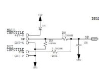
Looking at the six pin connector on ebikes.ca it is obvious what to do with pin 1 & 2.

I'm not sure what to do with pins 3,4 and 6.
For pins 3&4 I'm assuming I need to solder these to the ends of the shunt on the KU's PCB. Not sure if I need to cut the shunt though or leave it intact.
And for pin 6 I'm not sure if this is to join the signal of my hall throttle to the CA, or to join the CA to the throttle signal input on the controller? In both of those scenarios, in my mind I have three things to join, not two, so one is left unused.
If anyone could enlighten me I'd be most appreciative. Or perhaps it's not doable. I'm sure someone has attempted it before....
I was recently gifted a CA 2.3 with the 6 pin connector, including the speedo magnet + wire.
I'm keen to hook it up to a standard KU121 style 12 FET and try it out. I want to use the limiting features with RC lipo and a geared BPM hub.
Looking at the six pin connector on ebikes.ca it is obvious what to do with pin 1 & 2.
I'm not sure what to do with pins 3,4 and 6.
For pins 3&4 I'm assuming I need to solder these to the ends of the shunt on the KU's PCB. Not sure if I need to cut the shunt though or leave it intact.
And for pin 6 I'm not sure if this is to join the signal of my hall throttle to the CA, or to join the CA to the throttle signal input on the controller? In both of those scenarios, in my mind I have three things to join, not two, so one is left unused.
If anyone could enlighten me I'd be most appreciative. Or perhaps it's not doable. I'm sure someone has attempted it before....