Simulation is significantly different than actual results

Make More Pi

10 mW
Joined
Sep 1, 2014
Messages
20
Location
Livermore, California
This started as an email to ebikes.ca, who from here on I will refer to as GT, short for Grin Tech. GT graciously turned around a response in just a few hours. :) The answer is satisfactory but I would like to go into a few details on this subject and thought it would be beneficial to make this into a thread, so here we are.

I will be referring to the simulator at http://www.ebikes.ca/tools/simulator.html.

-- my message to GT --

I usually use peddle assist but I get a lot of questions about performance so I decided to do some hill climbing without peddling. I found that my performance did not reach simulation expectations by far.

I will focus on the steepest hill that I ran my tests on. It is 1.3 miles of 7.5% to 9%, mostly 8%. I started with a battery voltage of 54.6V standing still and ended with 51.8 V. I began at the bottom of this hill with a motor temp of 38.7C, ambient temp about 18.3C, and went full throttle. My total weight is 250lbs with 1.95”x26” wheels on a mountain bike frame. My current limit is 25A. The CA says my bat resistance is 0.06~0.08ohm. I've set no power limit.

As I climbed this hill I believe my top speed on the bottom half was maybe 12 mph but was mostly around 9 mph. The slope, quite constant, 8%.

Almost 1 mile up I reached a slightly steeper portion, 9%, where my speed crept slower and got down to 3mph.

I watched my motor temp. At this steepest portion it was 85C. As the slope leveled out some, 8%, my speed increased, temp still climbing and it got to 90C where I saw the over temp flag go up and I could see the CA cut the current back, 21A. (That came after the 3mph portion) The peek temp was 95C.

Now lets run a sim. Clyte H3540, Battery 51.8V 0.08ohm 12.3Ah, 25A IRFB4110 Controller, full throttle, 26” wheel, mountain bike, 250lbs, 9% grade. Sim says 14.3 mph, overheat in 16 minutes.

14.3mph is 4 times 3 mph. So what am I missing here? I tell my friends to use your sim when they are shopping for parts but how do I explain this difference? I believe you have done a lot of good work with the sim :) ; have I done something wrong?

-- response from GT --

The simulator is not modeling the phase current limit of the motor controller as well as the effects of higher temperature on the motor winding resistance, nor saturation effects either, and so you need to be mindful of this especially in the region where the motor is in the current limited region and especially at low speeds near a stall.

The significant difference between 14mph here and 3mph here is not a factor of 4 in speed, but just a factor of _maybe_ like 15% in the torque output. ie, to climb a very steep hill at 14mph only takes a very small amount more torque on the wheel than to climb it at 3-4 mph, since virtually all the torque is needed to overcome gravity which is independent of your velocity. Therefor any factors (like increasing motor winding resistance, or stator saturation) that decrease the torque output of the motor in this regime will have a very large effect on the computed speed. Change your weight from say 250lb to 275lb and you'll see what I mean. Or change your 9% grade to a 10% grade.

I tell my friends to use your sim when they are shopping for parts but how do I explain this difference? I believe you have done a lot of good work with the sim; have I done something wrong?

I should probably have a note to be cautious of any results when you are down at <30% or so of the unloaded motor speed, since then these secondary effects have enough of an impact to significantly affect the results, as you are often right on the edge of the motor having enough torque for the task at hand or not. When you are not in the current limited regime, then simulation results are almost perfectly consistent with what you'd see on the ground.

btw, we are working on a simulation program that does indeed have full thermal modeling of the motor over the course of a trip, you can see beta preview of that here:
http://www.ebikes.ca/tools/trip-simulator.html

right click points the top graph in order to manually generated your elevation profile map, and then left click to drag the nodes around. %grade between adjacent nodes is shown in real time as you drag them.

-- end of response from GT --

Thank you, GT, for you response! :) If I understand this correctly, the short answer is that as the temperature increase my motor looses efficiency at low RPMs and temperature effects are not simulated at http://www.ebikes.ca/tools/simulator.html, correct?

Perhaps that should be enough but I'm seeking a deeper understanding. So I want to pick this apart. Hopefully this can benefit others with an opportunity to share knowledge or to learn.

The simulator is not modeling the phase current limit of the motor controller...
As I understand this, the CA is commanding the controller through the throttle signal and will only drive the throttle signal to the point that the controller is taking 25A from the battery. So that's our input limit to our controller. The phase current is what the controller is sending to the motor. I looked around the web to find a full spec sheet that could tell me more about this but have not found it yet. Does anyone have a link to it?

... effects of higher temperature on the motor winding resistance ...
I do know that as heat increases so does coil resistance. If you want to prove this to yourself, try this experimental. If you can, find an incandescent light bulb, say a 100 watt. Measure the resistance. You might be quite surprised how low it is, between 5 to 10 ohm. But, if you were connect that bulb to your bike battery (say 50V) through a current meter, you'll see a current perhaps in the range of 2 amps. Solving for R you get 25 Ohm. Yes, the bulb is vary hot and the resistance increased.

... saturation effects ...
Does someone want to tackle explaining what that is? I imagine it has something to do with magnetic flux.

I was really surprised at how poorly my bike performed on this hill. My guess is that if I were to wait for the motor to cool to around 23 C then I would see much better results. Nevertheless, this experiment has made these phenomenon stick out like a sore thumb. I want to understand the details. I'll appreciate the help.
 
Make More Pi said:
... saturation effects ...
Does someone want to tackle explaining what that is? I imagine it has something to do with magnetic flux.
Most likely he's talking about the stator's lamination (core), which in each motor has a different amount of current that will create teh maximum possible magnetic flux...once you reach that "saturated" point, any further current above that only produces heat, and does not create any more motive power.

So having too high a phase current just makes your motor hot faster and doesn't get you moving any quicker or faster or harder.


There's a few long motor discussion threads in the Motor Technology subforum that talk about the various effects of different things mentioned in your post; it's a lot to wade thru and there's a lot of stuff you have to learn to really understand it (whcih I don't pretend to do :lol:) including some math stuff....
 
I use the simulator at ebikes.ca all of the time. It's a great way to compare motors and juggle variables to see what happens. If you ride your bike on level ground with no wind and no pedaling the power consumption numbers it gives also are darn close. I've never tried to test its hill-climbing predictions with no pedaling though it does seem to come very close when I factor in my pedal input. Once you load the average hub motor down to where it is operating well out of its efficient zone power drops dramatically and as you found out heat builds rapidly.

I too was initially disappointed years ago with the hill-climbing performance of my very first E-bike. That bike had a little front 250W Bafang motor running on 36V and a 15A controller. It barely climbed a 4% grade! After that I only tried climbing a hill with no pedaling maybe one other time. This time it was a MXUS geared motor running on 48V/15A. Again it bogged down going up an 8% grade until at 6 mph fearing it would stall or overheat I began to pedal. As soon as I did the motor came to life again and I topped the hill at 14 mph. The moral was that low-power E-bikes really are hybrid vehicles which work best when both man and machine are doing their part. This is fine with me since that's exactly what I want. Now I never think about NOT pedaling up hills. Heck with my "biggest" motor, a Bafang BPM, running the same voltage/current you use I can zip up that same 8% hill at 20 mph-with only moderate pedaling.

If you do really want to climb hills without pedaling you are going to have to build a somewhat different E-bike. If you want to use a hub motor then gear down with a smaller wheel or a slower wound motor. Then up the voltage and current if necessary to get the power to climb at the speed you desire. If you get the right combo you'll climb faster with less heat build-up.

My recommendation however is if you don't mind pedaling is to simply continue to pedal up hills and don't worry about it. :)

-R

PS, It may sound odd but if your battery can handle it try a higher output controller. It's possible that if the motor makes more power the speed will stay higher but the motor will actually run cooler since it's running at a higher efficiency.
 
Thanks for the replies so far. The experiences that Russell mentioned with different motors is helpful. And thanks for the stab at saturation effects by amberwolf. I will go have a look at the Motor Technology subforum.

The purpose of my post is to understand the physics and math of the situation. It was something non-liner that I noticed while experimenting for my friends. I said, "hmm, there is something going on here that I want to understand better". It wasn't so much disappointment because that is not what I built the bike for. Although, friends of mine may want to build a hill climber so the suggestions are useful.
 
From Russel
It may sound odd but if your battery can handle it try a higher output controller. It's possible that if the motor makes more power the speed will stay higher but the motor will actually run cooler since it's running at a higher efficiency.

I've set my current limit on the CA to 25A to protect the batteries. I was thinking though, what would happen if I were to change to a 40A IRFB4110 controller but leaving my current limit to 25A. GT said
The simulator is not modeling the phase current limit of the motor controller...
I would like to see a spec sheet to see what is going on there. But to my point, would the 40A controller be more efficient in the situation I've described and give us a little more kick up the hill as Russel is saying? Or, is the motor the limiting factor due to saturation effects?
 
I know squat about why this happens or how. I'm too dumb to ever really understand it fully. But I do know this, for sure.

48v 25 amps will stall (no pedaling) on 8%, at the weight you are carrying. This is just laws of physics, your wattage perhaps should get you up the hill faster, but bottom line is 800w to 1000w will only climb the hill but so fast. The sim is impressively accurate on flat, but hills are just harder to simulate. Few are really that constant a grade for one thing.

This is ok if the hill is short, but yours was not. 9mph is stalling, whether the sim predicted this or not. All I know is, right about 8%, no pedaling at that level of power, you'll stall that motor. Unless you have a very low rpm motor, you are stalling it at 9 mph. So a short hill you can get away with. A long one will overheat the motor unless you stop to cool it. If you start to stall, start pedaling. Get that speed back up to 13-15 mph, if you have a 26" wheel, to minimize the heating.

Then once you heat that sucker up, what they were saying above is happening. You can feel it, same watts you saw at the bottom of the hill when your motor was cooler, but now it's just going bleah. Which just stalls you more, 3 mph now. By 3 mph, you may be running at 10% efficiency, Vicious cycle that ends when you melt the motor. To me, it does feel exponential. I felt it every time I melted a motor. It's fine to a point, then the torque just vanishes and your motor heats crazy fast.

Here's the good news. the H3540 motor should be easily able to handle 48v 40 amps. With 2000w, you'll easily climb that hill at 15 mph or more, minimize stalling, and you should be able to climb a hill like that 10 miles long without overheating. So if you want to climb that stuff no pedal, just give er more amps, so you stay out of that vicious stalling it leading to worse stalling cycle.

This will work fine with a larger motor with enough magnet to handle that power without saturating too much. With an old school 5304, I've climbed very long 8% grade hills without overheating, using 2000w, and enough pedaling to keep er close to 15 mph. Weight was 400 pounds. With the cargo pods unloaded, at 300 pounds, the bike will breeze up that mountain no pedaling.
 
Weight and low power makes it stall climbing. Stalling is the worst scenario, making heat and pulling power for nothing. There is the point where feeding more power actually does consume less, because it is transformed into forward motion instead of just being a stationary heater.

The HS is not a big motor, yet I have climbed such hills with them at 65 Kmh feeding 10 Kw, without excessive overheating. It is good for that kind of slope, and it can climb 20% for a few hundred feet, but 35% kills it in no time.
 
This may end up proving to be valuable if it gets the GT tech writers to add a steep failure curve to the simulator. I suspect they haven't paid much attention to this portion of the simulator, because...almost nobody spends any time with that combination, so until you wrote them, nobody was interested in that graph. They have only so much time to spend on simulator upgrades (which is ongoing, MXUS, etc).

I just skimmed the above posts and I'm going to issue a blanket "I agree with all of them", but specifically, dogman nailed it on the head.

It sounds counter-intuitive that more amps would help the hub run cooler (thats nuts, right?). the problem is the magnet speed. Low amps bogged down and then when the magnets slowed down, the coils being energized had almost no "OFF" time. More amps would help it accelerate more easily (more amps/more power) so...the higher magnet-speed across the coils leads to shorter "ON" times and longer "OFF" times.

Here's a poorly though out example:...as an average adult, I can dead lift 100 pound three times...but I can't lift 300 pounds once.

You are correct in that the simulator doesn't show how this combination is a fail. Lets pretend you are a close personal friend of mine, you have a budget of $2,000...and for some reason, you want to tackle steep hills with a 35mm width-stator DD hub.

You insist that you want to use 50V / 25A in a 26-inch wheel, and there's your problem right there. You need to change one of those parameters, and changing two of them would be better. Switch to a smaller diameter tire and then up the voltage = same top speed, but with a higher magnet-speed inside the motor (17-inch moped rim with 60V-72V?).

Saturation: there are many factors that will affect when a motor reaches saturation (and I'm not going to pretend I understand every aspect), but...all you need to do is this: data log the motor temps. Run the motor through a medium but constant load, and time the acceleration. Raise amps a little and repeat. Each time you raise the amps a little, temps will go up a little, and times will decrease a little. Then...there will arrive a moment when the same increase in amps only improves the acceleration half as much as it had been halping befpore, and the temps will rise twice as much as it did before. THAT...is that particular motors saturation point. More amps above that will improve acceleration, but not as much as before, and the heat will rise on a much steeper curve.

edit: Don Garlits wasn't interested in efficiency, just acceleration. I say that to point out: you can drive a nail into a board with a pipe wrench (I have done it), but...a hammer works much better. If you don't mind running an in-efficient system with a lot of waste-heat (you don't have to explain why you want that) just improve the motors heat-sheddimg. Oil cooling first, and after that, ventilation holes.

"Definitive Tests on the Heating and Cooling of Hub Motors" (justin_le, 23 pages [includes links to many oil-cooling/ventilating-sideplates threads])
http://endless-sphere.com/forums/viewtopic.php?f=2&t=48753

"Oil cooling your hub- NOT snake oil!" (spicerack, 23 pages)
http://endless-sphere.com/forums/viewtopic.php?f=2&t=37972

"Temp sensor that's too cool not to share" (Auraslip, 4 pages)
http://endless-sphere.com/forums/viewtopic.php?f=1&t=25502

"Using 16/17/18/19-inch moped rims on large DD hubmotors" (spinningmagnets, one page [plus many links to other threads])
http://endless-sphere.com/forums/viewtopic.php?f=2&t=69104&p=1048226#p1048226
 
I suspect that the answer is much simpler. Once a motor drops in speed below 50% of its maximum speed, efficiency drops like a stone, so anything that slows the bike a bit like wind or a slightly steeper hill will tip the motor into a spiral of decreasing efficiency and power until it stalls out. Try running the simulation again with the hill increased a couple of percent.
 
FWIW, when I compared the motor sim's time to overheat up a hill with my real world experiences, I found my time to overheat much longer than the sims. Yours was shorter that the sims in the real world, because for some reason you stalled more than the sim predicted. We don't know why that happened yet!

It could be as simple as one poor phase wire plug connection cut your power to one phase by 75%. Or something similar happening inside your controller. You would not notice this till you put a very heavy load on it. But the result would be a motor pulling at about 1/3 the torque it should have been. So your test result could be something like that is going on. Likely not, but it's possible for sure.

When it happens on another similar bike, that's real data. One data point does not make a graph. However, your 9% grade with no pedaling would stall the motor some for sure at the power level you were riding, but I would still have expected it to make it without stalling that much, enough to slow to 3 mph. A longer hill sure, but you only had a mile and a half. I do smell a rat, like a phase wire got hot.

I get much longer time to overheat mostly because I pedal some up the hill. But on no pedal tests, I may have slight a tailwind due to the orientation of my test hill. Also, the test hill has some short but significant flat spots that give the motor a short rest and let me build up some speed again. It's three miles long, a mile each of 5%, 6%, 7%, and just a short 8% at the end. A typical 9c type hubmotor, with 1000w will get my 190 pounds to the top without melting, but it starts to stall on the 7% part (slowing to close to 12 mph or 25% of max loaded speed), and will get pretty hot. Just some very moderate pealing effort eliminates the severe stall (back to 15 mph), though the ride is still slow enough magnet speed to get pretty warm.

My point is, its just really hard to find a hill of any length with a constant grade, and always there is nearly always some difference in weather conditions. So the real world just never quite matches a sim perfectly, except for no wind, and pretty flat ride that is repeated in both directions, on a truly windless day.

When I have done tests on those conditions, the GT simulator was astonishingly accurate.
 
dogman, that's good advice to check my phase connection. What is your recommendation as to how I could troubleshoot that?

It is my belief that when doing an experiment one must record as much about the conditions as possible. When approaching unknown territory one does not know even what information is important.

My initial post gives the conditions that I recorded on my little 3x5 cards for that run. I have read all of the posts you all have given to this point. From what I have read, I surmise that initial motor temperature and ambient temperature is important, as well as current limit (which translates to max power). Good thing I had the where with all to record them.

One might ask, "how it is that my initial temperature for that run was 38.7C when the ambient was 18.3C?" The answer to that is, before that run, I rode the 8 miles to get there and did two prior experiments. To this point, in the interest of brevity, I did not give a synopses of my prior up hill experiment. (The other test was downhill regen.) But now I see that giving that synopsis can be beneficial.
One data point does not make a graph.

It is 1.6 miles of 6% with a short steeper bit, 8%. I started with a battery voltage of 56.2V standing still and ended with 53.7V. I began at the bottom of this hill with a motor temp of 28.0C, ambient temp about 18.3C, and went full throttle. My total weight is 250lbs with 1.95”x26” wheels on a mountain bike frame. My current limit is 25A. The CA says my bat resistance is 0.06~0.08ohm. I've set no power limit. (Same as the other test.)

My speed for this run ranged between 12 (on the 8% bit) and 20 mph. As I crested the hill I reached 23 mph. My final temperature was 76.0C. 8)
 
[1] Re: Simulator 'Time to Overheat' Estimate
The simulator page says it concisely without commentary:

simulator page said:
Overheat In:
This is a prediction on how long it would take the motor to overheat (reach 150oC) based on a simple first order thermal model that assumes the motor is not spinning and in still air. The actual time to overheat on a vehicle moving outdoors and associated air cooling would be substantially longer.
It works exactly as advertised -- you just need to take the time to read the advertisement....


[2] Re: Speed Estimate

Justin's first remark describes the largest factor in the discrepancy:
Justin said:
The simulator is not modeling the phase current limit of the motor controller as well as the effects of higher temperature on the motor winding resistance, nor saturation effects either, and so you need to be mindful of this especially in the region where the motor is in the current limited region and especially at low speeds near a stall.

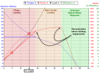
For illustrative purposes, here's a simple example of what is happening (and not happening) in the present simulator:

simulatorNoPhaseLimiting.png
In small steps:
  1. We know the simulator estimates speed as the intersection of the black 'Load Line' and the red 'Motor Power Curve'. This is the speed at which the power necessary to propel the bike (LoadLine) equals the power the motor can develop (Motor Power).

  2. The simulator does not model controller phase current limiting so there is no 'red region' (instead the orange battery current limited region stretches all the way to 0 rpm) and we get the red and black solid curves just as shown. But we can use the plot to show how the controller might actually be operating and what the simulator 'should' show with phase limiting in play:

  3. PWM is in effect in the red and orange regions and the controller takes the battery voltage and battery current (battery power) and according to load transforms them into entirely different phase currents and phase voltages (roughly the same power). By the blue torque plot, we see torque climbing to the left as more torque is required under larger load as we approach 'stall' (stall = 0 rpm). Although we can't see phase current on the plot, since torque is directly proportional to phase current we know that the controller must be cranking up the phase current to provide the indicated increased torque to carry increased load as we move to the left. At least that's what the simulator says - but the real controller works differently...

  4. In the red region a real controller is programmed to limit torque by limiting the phase current . This limiting can be fixed, some factor of the battery current (e.g. 2.5x), and either be 'actually measured' or 'an estimate'... This is done in various ways by different controllers and each different method drastically affects the result. For simplicity in the example above, we assume the phase current is just limited to a constant fixed value - and since torque is proportional to phase current (which is limited to a constant value) the torque is similarly limited to a constant value. If we were to model it, this would be the blue dotted line in the red region. So - instead of the current and torque ramping up towards 0 rpm, they flatten out.

  5. Since power is RPM x TORQUE and the torque is now constant in the red region, the Motor Power varies more or less linearly with rpm (speed) and we get the Motor Power curve re-shaped to the more or less linear dotted red line while phase current limiting is in effect. The new red Motor Power curve now has two points of discontinuity where phase and battery current limiting are in effect - and importantly - has reduced power in the red region (dotted red line is lower than solid red curve).

  6. Here's the payoff for sticking with this :) : Due entirely to the controller-limited reduced power in the red region - the NEW INTERSECTION of the black Load Line and the dotted red 'Phase Current Limited' Motor Power Curve is now down around 4-5mph. Although heat and other factors are playing a role, basic controller operation can explain a great deal about low end performance. Adding phase current limit modeling (the red zone) would make the simulator estimation strategy give a more reasonable prediction under heavy loads (if we knew exactly how a particular controller did limiting).

  7. FWIW - Reprogramming the controller for higher phase currents raises the torque and power curves in this low region. This coincides with observed behavior where high phase current settings have little effect at the top end but dramatically affect getaways and improve loaded low end speed (at the expense of higher waste heat).
In any case, it's clear the controller is typically only in phase limiting under severe loads. What we might consider 'healthy' or 'safe' continuous (non-accelerating) motor operation is typically up in the orange and green regions and in these areas the simulator does a very good job of predicting behavior.

Justin said:
I should probably have a note to be cautious of any results when you are down at <30% or so of the unloaded motor speed, ...
Like any tool, the simulator has shortfalls, but its utility is realized when you play to its strengths.
 
Thanks teklektik! You put a lot of work into that. :D It is helpful to visualize what is happening when the controller is current limiting. Is anyone able to locate a spec sheet for the 25A IRFB4110 Controller (Grinfinion), so that we can know what the current limit is? I guess your dashed lines are somewhat arbitrary since we don't know what the actual current limit is on the phase lines, correct? But it does explain why we could have a lower up hill speed even before the motor begins to warm up.

It sounds to me that although current limiting is a factor to contribute to a slower uphill speed I think the temperature effects overcome the effects of current limiting as we continue in this low speed, loaded mode.

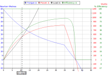
The plot below was generated with the same parameters as the simulation that I mentioned in my first post with the exception of the controller. I switched from a battery current limit of 25A to 20A to hopefully model the effect of phase current limiting.

hill_plot.png
What I want to point out here is this. Notice the Efficiency line in green. At 10.5 mph, the Efficiency is 54%. The leaves a 46% loss. At least a portion of that loss is in the motor. Losses in the motor turns to heat in the motor. Heat in the motor means our Efficiency curve gets attenuated. As our efficiency goes down our speed goes down etc. A downward death-spiral-feed-back-loop. :shock:

Edit : ERROR :oops:
John in CR said:
It's inefficient because it's making low power (torque X rpm = power), not because it's making more heat. Current is what makes heat with copper losses being current squared times resistance.


teklektik let the cat out of the bag. :wink: It is my intention to honor anonymity and since I was unable,while writing my first post, to determine justin_le's handle I called him GT for lack of a better idea. justin_le is the man!

I have said, I think the simulator is excellent work! :) I'm not knocking it. I have spent a lot of time using it and reading the simulator page to learn how to use it and understand what it means in order to make my e-bike part purchasing decisions last summer. I have spent to date about $1500 with Grin and am very pleased with the results. The only reason that is not over $2000 is because I bought my batteries from EM3ev.

I am keenly aware that when real results do not mach current models then there is something to be learned. That is the purpose of this blog topic. Before I emailed justin_le, I honestly thought I could be doing something wrong.

This just occurred to me :!: When you are on any incline you would need a certain amount of power (or toque) just to keep from rolling backwards.
simulator page wrote:
The load line ... directly shows the amount of power necessary to move the bicycle.
If a Grade >0% is simulated, shouldn't the load line start at a value that is >0W to keep the bike still, not rolling backwards? :roll: Hmmm. But the load line in the plots always starts at 0W. Could this be another flaw in the simulator?

Edit : ERROR :oops:
Power = Force x Velocity
or
Power = Torque x Rotational Velocity (i.e. RPM)

The load line is power. There is no power without velocity. Therefore the simulation is correct to start the load line at zero.
 
Welcome to ES, Make More Pi! Looks like you are not far from me.

You are getting some great feedback here, and I'll add a little piece to the simulator interpretation that most folks miss.

The simulator is a dynamic run at wide open throttle (WOT). It is not a set of stable data points. This answers your question about time zero power. At time zero the bike is standing at full throttle, full torque is already generated, but no velocity has yet accrued. The bike is accelerating along the graph, and in reality it would stop at the point where the load line intersects the output power and go no further, but of course they continue the calculation to the end. Because it is accelerating at all points below that, interpreting the graph has to be done carefully. Efficiency for example is not computed for cruising at each speed, it is an efficiency for the accelerating condition at WOT, which is much lower than it actually is when we reduced the throttle to run at a lower speed. You can play with the throttle and find these solutions in the graph. The data is only static (not accelerating) at the one crossover point. Everywhere else it is either accelerating or beyond the crossover where it would actually be decelerating.

The simulator is based on real measurements of motors and good physics but it is not fully detailed and is missing some important variables such as motor temperature's effect on winding resistance and the phase current limits of the controller. As we get close to the balance of torque and gradient these small differences become quite important, so the no-pedaling crossover speed can vary quite a bit. One way to look at this situation is that the motor can mostly compensate for the gradient, so pedaling power becomes very important, a near stalled motor can easily be pedaled to 12 mph up that hill, as the pedaling is only working against air resistance and the motor torque is doing the climbing (effectively neutralizing the gradient). This is a small proportional change in total torque and power but it makes a large change in resulting speed.

The simulator accuracy is better for level runs when the load is primarily air resistance and it increases exponentially, in this case a small error in torque makes a small error in velocity, whereas on a near stall calculation the small error causes a large shift in the solution.

To achieve good speed up those hills you need a bit more torque. Even a modest increase will make a big difference. Experiment with higher current and use the temperature sensor to protect the motor and controller against overheating.
 
I've got an old 1000W motor from yescomusa, HBS-48V1000W. I run it on 24s rc lipo on a 40A 1500W 15 fet 4410 controller. The sim says I can only get ~9mph up a 20% grade with an H3540 motor and a 40A 4110 fet controller, when in fact I can accelerate up to ~30mph up the grade with my cheap setup. And I sure as heck can't pedal above 20mph. I can do the same thing with the 3000W mxus motor too where the sim says only ~13mph. Using a 0% and -% grade, it's fairly accurate, but for uphill grades it seems to be way off. And that's with changing the battery ohms from 0.2 to 0.02 so there's almost no sag like you get with rc lipo.
 
By one point on the graph, what I meant was one bike/motor/controller. And one trip up the hill.

I still smell a rat, that you actually slowed to 3 mph. But perhaps it was just that you started the experiment with a fairly warm motor. Then got warm enough to tip into overheat when you hit the 9%.

Not surprised that Wes goes faster than his sim. That's more typical. But what makes me smell a rat, something not right on your bike, is you are that much slower than the sim predicts.

I think it could be pretty simple, like a poor connection on a phase wire. This might only show an effect after some riding warms it up too. But it might also just be the previous tests skewed the motor heating.

For sure, repeat the test with as close to a stone cold motor as you can. At the top, feel for hot spots in your wiring.

When I did my motor melt off tests years ago, I took the bikes to the bottom of my big hill in a car. So I could start out with the motor at ambient each test.
 
Make More Pi said:
I guess your dashed lines are somewhat arbitrary since we don't know what the actual current limit is on the phase lines, correct?
Yep - as I noted, this is simply an example to help folks understand how the controller works and affects motor operation -- and what sort of inaccuracy we might therefore expect in the simulator. Totally 'made-up' dotted lines :D

Make More Pi said:
But it does explain why we could have a lower up hill speed even before the motor begins to warm up.
That's exactly (and only) what the phase limiting example shows. Just like our example, the simulator does not take motor temperature into account - it has no idea what the temp is so the estimates are 'cold motor' estimates.

Make More Pi said:
Is anyone able to locate a spec sheet for the 25A IRFB4110 Controller (Grinfinion), so that we can know what the current limit is?
You are no going to find any such spec.

Again - different controllers limit in different ways. For example, the common 'Infineon' controllers do not measure phase current, they estimate it from battery current using a magic proprietary technique that is based on commutation frequency, battery current, and some 'typical' motor phase resistance and inductance. Obviously this phase current estimate is wrong for every other (non-typical) motor..... So if the estimate is off, the configured phase limit is going to have an entirely bogus effect - and in an unknowably proprietary way :? . The simulator would need to simulate this bogus wacko operation - and different wacko schemes for every other controller.

I leave it to you to decide if Grin never thought of simulating phase limiting or if they actually did, but couldn't see a presentably understandable way to make it configurable - or accurate.

Make More Pi said:
When you are on any incline you would need a certain amount of power (or toque) just to keep from rolling backwards.
...
If a Grade >0% is simulated, shouldn't the load line start at a value that is >0W to keep the bike still, not rolling backwards?
No. You are confusing some basic physics definitions (oops!).
Power is RPM x TORQUE - with no rpm there is no power. You must apply a force to stop the bike from rolling backwards at standstill, but that is FORCE not POWER - two very different concepts. Back your bike up to a street sign on a hill to keep it from rolling backwards - a force is applied by the sign but no power is expended.

Since this is a power plot and there is none at 0 rpm - all is shown as it should be.
 
When you look at efficiency and see it very low at low speeds, don't think of it as making more heat. It's inefficient because it's making low power (torque X rpm = power), not because it's making more heat. Current is what makes heat with copper losses being current squared times resistance.

On the current side, the motor sees phase current, which can be significantly higher than the battery current limit you see. The phase current limit is what you'd want to know, because the commonly used 2.5:1 ratio of phase to battery current limit can cause lots of extra heat during climbs.

On the resistance side, in our temperature ranges the resistance of copper increases by about 0.4% for each 1°C of temperature increase. That means for the same current your motor was making over 22% more heat at peak temp vs at the start of the hill.

When you bog down like that the lion's share of what comes out of the battery is turned into heat instead of work. eg 4mph up an 8% grade with 250lbs only requires 175W of power at the wheel. The rest of the power coming out of the battery was turning into heat, and at low rpm motors shed heat more slowly, making matters even worse. 14.7mph requires 733W output at the wheel, but the power increase comes mostly from the increased rpm with only a small increase in torque (current) needed like Teklektik stated earlier. 14 vs 4mph is 3.675 times higher rpm, but power at the wheel to do maintain it is only 4.19 times greater, so only 2-3 amps more is required to create the greater torque needed for the significantly greater speed on the climb.

Since you ride in hilly terrain, I'd suggest forgetting the thermal cutback. That's because lowering the battery current can actually cause a heat problem, just like it probably did in your case. Instead set the temp somewhat higher (yours is overly conservative(, and make it a hard cutoff instead of a cutback. Since you help the motor with your legs and run relatively modest power, the only way you can overheat your motor is by bogging it down with too steep a hill unless you end up riding in unusually high ambient temperatures.

John
 
John in CR said:
I'd suggest forgetting the thermal cutback. That's because lowering the battery current can actually cause a heat problem, just like it probably did in your case. Instead set the temp somewhat higher (yours is overly conservative(, and make it a hard cutoff instead of a cutback...
That's good advice generally but I don't see these temperatures when I ride normally. Before this, I had not seen temperatures above 65C. This was a science experiment.

You are correct. I did hit thermal cutback, 90C, but not until after I started to pick up speed due to a slight decrease in the slope (from 9% to 8%). When I was near 3 mph the temp was 85C. On the edge but not quite there yet. I kept going for anther 0.3 miles or so. You bet I was watching the temp closely. I had nothing more important to do going 3mph :wink:

dogman dan said:
By one point on the graph, what I meant was one bike/motor/controller. And one trip up the hill.
I agree. Change only one variable at a time if possible. I hope to find time to go back and gather more data. Start with a cooler motor. Check for hot spots in the wire harness after the run.
 
Let's perform a thought experiment on this system climbing a hill. If we take the OP's bike and motor, but we have an unlimited battery/controller that we can dial to any current, how do we operate it to optimize the climbing of the hill without melting the motor?

So let's dial this powerful current source (motor and controller) up from zero and see what happens. Assume the bike won't roll backwards. As we apply current we get torque and heat, but no motion until the torque exceeds the torque load from the gradient. As the torque grows past this balance point the bike begins to accelerate, and reaches a constant speed where the gradient and air resistance and other losses balance the torque developed by the current. The heat produced in the motor is dominantly from I squared R. The torque is proportional to I. The heat in the motor integrates over time and raises the motor's temperature. There is some cooling, but for short steep climbs it is not enough so the motor temperature increases.

As the motor heats R increases and makes the heat generation worse for the same current and torque. So we can see if the current is too low it will only succeed in heating the motor and either no motion, or slow motion will result, and time is our enemy here as the motor heats up, if it takes very long the motor will overheat as the heat dissipation capability of these motors is not great.

Lets keep increasing the current. As we do that the acceleration and velocity up the hill increase with the current, but the heat increases with the square of the current. If we hit the motor with enough current, the heat will cause a failure in a very brief period of time, before much progress has been made up the hill. So there is such a thing as too much current.

Above some level of current the torque ceases to increase linearly, and grows at a lesser rate. I squared R continues to grow as the square, but torque production is no longer growing as quickly. In this region the motor is even less efficient.

So there is a current somewhere between zero and rapid destruction that will produce the least integrated heat (the combination of heat and time), or the lowest temperature in the motor while climbing this hill. This may or may not be little enough for the system to climb the hill successfully without melting.

The more torque that is generated, the greater the speed reached, and the greater the air friction losses, which grow exponentially, and the I squared R motor heat is growing as the square, plus the increased R factor from the hotter copper. Many factors are growing quickly toward motor overheating and destruction.

Adding torque that causes speed to increase will reduce the time to get to the top. Clearly cutting the travel time climbing the hill is important to reducing integrated heat and final temperature in the motor. So going faster helps. To a point. But at some point the savings in time to the top is not as beneficial as the increased rate of heating.

Knowing the winding temperature in real-time is useful. If the temperature is too high the winding insulation will fail instantly. At some lesser temperature the insulation is not endangered, but the halls and magnets will be damaged only if this condition persists for a longer period of time. So protecting the motor with temperature sensors is not a single valued threshold, but a more complicated calculation, or multiple sensors at the different points with different thresholds.

The bottom line is that increasing the current above the stall current will increase speed and reduce time to climb thereby reducing the temperature in the motor at the top of the hill until some optimal current value, beyond which increasing current will increase the temperature in the motor to climb that hill. We'd like to know that "best temperature" value of current. The minimum motor temperature may be achieved by using a higher level of current to accelerate to a speed, and then a lower value of current just sufficient to maintain that speed, and minimizing the I squared R heating. This happens naturally with real battery and controller combinations since the velocity increases and the back EMF reduces the current when some equilibrium is reached. So the current doesn't stay constant for the climb.

Depending on the motor, the hill, and the starting conditions, it may not be possible to climb the hill without destroying the motor. While a different starting condition (cooler temperature) may allow success. I've witnessed a motor climb a steep hill, and then go back down and try a second time (while still hot) and fail, burning up. It takes a surprisingly long time for a motor to fully cool off. Especially if it is sitting without moving air or cooling vents.

Adding pedaling input can reduce the heating in the motor significantly. Even a modest pedaling input can make a huge difference. Take the example where the torque is exactly enough to offset the gradient. Without pedaling there is 0 velocity, and the motor will sit and cook. With this same current a rider can pedal the bike on the gradient to 12-15 mph, or whatever speed they can pedal this unpowered bike to on a level surface. The motor heating is the same, but now the top of the hill will be reached whereas at zero velocity it never would. So now there is a chance that the hill can be successfully climbed. I have experienced this condition where a modest pedaling input makes a huge difference in velocity and therefore a reduction in motor temperature at the top of the hill.

Predicting the current and resulting speed to climb the hill and produce minimum heat in the motor is not simple. This motor has a fairly low speed efficiency range, high speeds begin to add more losses from hysteresis and air resistance. So I suspect the optimal speed to climb is 10-15 mph, but that is just an estimate. Too slow takes too long and integrates too much heat. Too fast requires extra torque that drives the I squared R losses and the air friction and the dynamic motor losses up too quickly even though the time to climb is less.

If you don't have enough torque to make 10-15 mph I think pedaling to make that speed is imperative, and that motor temperature needs to be watched. If it gets too high you need to stop climbing and cool the motor.

So, to answer your question, more current and speed can reduce motor heating over the hill climb, and reduce overall temperature. But exactly how much is hard to predict, and excess current will cause motor overheating and failure faster than the optimal current.

In the standard Engineering vernacular, "it depends".

In the real situation, I would want a controller that is capable of enough current to generate full motor torque at least up to the point where the current versus torque curve changes slope, or perhaps a little beyond that, AND a temperature sensor to see how the motor is doing. Alternately an IR thermometer or finger and frequent checks for temperature are indicated. After a time you will get a feel for what hills (gradient, distance) will heat the motor up.
 
That's a good exercise Alan B. So, in your scenario you are keeping slope, mass and battery voltage as I have previously stated?

Are these two statements in conflict with each other?
Alan B said:
The heat produced in the motor is dominantly from I squared R... The heat in the motor integrates over time and raises the motor's temperature. There is some cooling, but for short steep climbs it is not enough so the motor temperature increases.
...
Lets keep increasing the current. As we do that the acceleration and velocity up the hill increase with the current, but the heat increases with the square of the current. If we hit the motor with enough current, the heat will cause a failure in a very brief period of time, before much progress has been made up the hill. So there is such a thing as too much current.

spinningmagnets said:
It sounds counter-intuitive that more amps would help the hub run cooler (thats nuts, right?). the problem is the magnet speed. Low amps bogged down and then when the magnets slowed down, the coils being energized had almost no "OFF" time. More amps would help it accelerate more easily (more amps/more power) so...the higher magnet-speed across the coils leads to shorter "ON" times and longer "OFF" times.

True - Power, if it is all producing heat, is (I^2)*R. Heat is the integration power over time minus heat dissipation over time. But isn't there a point, when higher RPM is achieved with increased current, where much of the power is producing torque instead of heat?

Alan B said:
Above some level of current the torque ceases to increase linearly, and grows at a lesser rate. I squared R continues to grow as the square, but torque production is no longer growing as quickly. In this region the motor is even less efficient.
Wouldn't battery voltage have to be increased in order enter this region of operation? You can lead a horse to water but you can't make him drink without a cattle prod. You can increase your current limit but the extra current will not be used unless there is a higher voltage behind it. I=V/R. Not wanting to sound arrogant but I am just trying to be understood and to understand.
 
Back
Top