Powerchair Direct Drive Brushless Motor (High-Torque)

ur right about muprhy; couldn't get my moto r or ocntroller so got my han d worse instead.

t/s of controller using this from mdd0127
DSC05671.JPG
shows the two red-cirecled ones just flash a bit dimly and go out every cycle, while other four rotate in pairs, when i couple phase and halls on tester to motor color-to-color. so i assume that means something s wrong with whichecer phase/hall thar t horizontal pair is for. dunno yet how to tell wich one.

meant to take vid but forgot till adter all unhooked.
 
I hooked up the Timing Adjuster 2 from Mdd0127 today, and did a bit of basic experimentation.
DSC05859.JPG


i don't know yet if adjusting the tming of the halls will actually do anything helpful, but the results are visible and audible in the videos below.

retarding timing from 0 to 10 degrees using potentiometer
[youtube]b-8mLXsO4FE[/youtube]


advancing timing from 0 to -10 degrees using potentiometer
[youtube]3wkVsZsA04g[/youtube]

current doesn't change much when retarding, but it increases aby up to 10% during advance, depending on speed and degree of advance.


i think for more experiments with this i need to bolt the motor down to something immovable, because at one point i accidentally changed the wrong data set and clicked to send changes to the TA2, and forced the timing to change from -6 degrees advance to 5 degrees retard instantly at full speed. :lol: :oops: it almost pulled everything off the table as it suddenly just STOPPED and dissipated the rotor's momentum into the rest of the motor and the connected equipment. :( Nothing broke, but it could've been disastrous. :oop:


Further experiments once I learn what i am actually doing with this thing. ;)
 
Wow, Amberwolf rocks! Looks like a cool topic too, I wanna see how good the motor ends up. I didn't know a person can know that much about motors and controllers.
 
I know almost nothing about them...if you want someone that really knows about them, talk to Lebowski, Rickynz, Bigmoose, Miles, Jeremy Harris, Arlo1, Liveforphysics, Thud, Methods, and list of others that would take too long to type out. :lol:

I do hope I get time to go back to this experiment again soon, though. I really wanna see what happens on a bike with this thing, and I am sad that I don't know yet. :(
 
I have come up with an idea for moutning this motor in a bike-usable way without nearly as much effort as I had thought, though it makes it a direct-drive, rather than thru a transmission--but it would at least let me test it's usability under power and load.

This is a sketch from the Loooooooongbike thread, where idea pondering while at lunchtime at work inspired this idea:

loooooooongbike rev b1.JPG


All I have to build to make it work is a plate that bolts to the hubmotor's magnet ring cover bolt holes, and to the five outer bolt holes on the powerchair motor's rotor face. I'd also want to lathe the rotor outer circumference just a tad, so that the magnet ring will slip all the way down to the tirebead seating ring on it.


The bad part is that the magnets themselves would be loadbearing in this case, unless I also made another ring for the inside face of the ring that extends just a hair beyond them, to rest on the powerchair motor's rotor.


Then I would need to make a plate that is welded to or bolted to the rear triangle of a bike, that the backside of the powerchair motor can bolt to. It has to be stiff as it must bear the torsional forces of the weight of the bike, as it's effectively a single-sided "swingarm" without being a suspension element (fixed in place).


None of the needed things are very hard to do, and would mean I could bolt this thing onto AFAIK *any* existing 9C or MXUS DD hubmotor magnet ring thats' already built into a wheel of any size. Even some GM hubs should fit it, though the bolt holes might be differently sized or spaced on the magnet ring.


I dunno if I will have time to do the experiment, but I'm a step closer now. :)
 
Another sketch from lunchtimes:
powerchair motor in hubmotor sketch 1.JPG


Shown as mounted by the right side, I think I would actually mount by left side, so that I can bolt a freewheel-threaded hub flange to the right side, to be able to still have a "legal" bicycle, with the chain still attached to the wheel.

Also, if I use a pillow bearing on the right side I can add a short bolt or axle threaded into the center hole of the powerchair motor's rotor, to give support on the right side, so it doesn't have twisting forces from weight/load on the left side mounts.


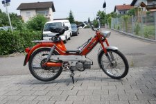
To test on CrazyBike2, I would have to replace the present bottom rackmount strip cargo pod support with 1" square tubing, same as the top, to give a sturdier place to bolt the motor itself to. This is something I have planned to do just for stiffer cargo pod support anyway, but never gotten round to.


Right now the thing mainly keeping me from just going ahead and doing this is that my lathe is buried under a bunch of stuff int eh back room (which will take me at least a day or two to move, as I wont' have the energy to do it all at once), and I am not sure that the bed is large enough to hold the discs I have to make the adapter plate and ring from.

I might have to find someone else here on ES that could do it and trade them work or parts or something. I guess when I get to where I have time to try this whole thing out I can put up a want ad for that. Doesnt' need a lathe, even a 2D CNC could do it, if it can cut thin steel (1/8"?) or thick aluminum (1/4"?), as they are just flat plates.

I *might* be able to cut them out by hand, using a compass to scribe lines and then cut roughly with angle grinder, then file and sand until as close as I can get them, but I expect a fair bit of runout this way.

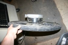
The rotor I can "lathe" by simply bolting the motor down flat and then bolting the lathe's toolholder down to the same table, or strapping the motor down to the lathe bed sideways, close to the toolholder, once I unbury the lathe itself.


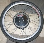
Then I have to locate bolts (m7? m8? bigger?) that will fit the threads/holes on the rotor face for the outer holes, and then longer ones than presently there for the center of the rotor to secure the freewheel to it as well as the rotor to the axle inside. Also need cover bolts for the hub flange, as I know I don't have enough of those without taking them out of a working hubmotor. (M3? M4?)

Pretty sure I already have a bolt or axle the right size for the center hole, and I have a pillow bearing I can use that I got from (I think) mud2005, along with some other stuff (might've been someone else--veloman maybe?). (I usually label the boxes I keep stuff in so I knwo where ti came from, but I forgot to with a coupel of them and can't recall right now--would have to look thru my build threads to see if I noted it down there).


Getting the other stuff done to the bike to bea ble to put hte motor on is relatively trivial, I just have to do it in a way that doesn't preclude taking it right back off and putting the regular motor wheel back on--should be easy enough.
 

Attachments

  • Powerchair motor in Hubmotor magnet ring IMG_6545.JPG
    Powerchair motor in Hubmotor magnet ring IMG_6545.JPG
    73.6 KB · Views: 3,606
  • Powerchair motor in Hubmotor magnet ring IMG_6550.JPG
    Powerchair motor in Hubmotor magnet ring IMG_6550.JPG
    35.4 KB · Views: 3,606
Where is this motor now? :D
 
Well, after the house fire it sat for a year in the shed outside (I am surprised it didn't get stolen with other stuff when thieves broke into the sheds during the rebuild, since it was in plain sight). Now that I've been back in the house for a few months, I've moved it inside the house with some other stuff for the new bike build (which I am still no further along on for a number of reasons, mostly indecision and not wanting to / being able to work in the heat).

But AFAIK it should still work like before, and I just have to get it attached to a controller powerful enough to do what I wanna do with it, and a bike sturdy enough to not twist with the torque. ;)


It is most likely to end up as the middrive motor on the new bike, though it is possible i wil still try it out once as the side-mounted hubmotor with regular bike hubmotor rotor bolted on the outside of it's rotor as pictured just above.


I'd planned to put it on the new bike I was gonna be building during the vacation I'd just started when the fire happened, so I dind't get to do that yet. (I planned a lot of stuff for that week...most of which I've forgotten and osme of which isn't evne possible anymore cuz the stuff itself no longer exists or was stolen, and soem of which became pointless cuz the dogs it was for are all gone now...though I have others now instead that might need something similar).


Anyway, enough complaining....it'll get used on a bike as soon as I can manage it, cuz I still really wanna know how it will perform. :)
 
Man that fire just gets sadder :(

Any name or part number on the motor? I want to try to find one :D

I also want to see how it performs!
 
Skalabala said:
Any name or part number on the motor? I want to try to find one :D
http://www.endless-sphere.com/forums/viewtopic.php?p=486970#p486970
There's also another powerchair motor thread somewhere by another member with a slightly different version of this.

If you have anywehre around you that services these things, you might get one cheap if it's brake is worn out.
 
Since I've done some upgrading and stiffening of CrazyBIke2's frame (instead of building the other new version of the bike), I've been pondering building this onto the bike to drive the rear wheel via chain.

Exactly *how* I"m nto sure yet, but at least now the way the frame is built back there, it's MUCH easier to make a plate to bolt this motor to.

Now, one possibility is using some belt sprockets I have, but I'm not sure they'll take the power I would put thru them--or rather, I'm not sure the belt itself would.

Another possibility is using some gears I think are timing gears, which I think have helical teeth. For that I'd sort of have to make a box to contain the gears and their lubricant.

The simplest method is of course just a regular chain and sprockets. Since I don't think bike chain or sprockets will handle the power I'd like to be able to put thru this for startups from a stop with a really heavy load, I'd probably wanna use a double chain and sprocket, side by side.

I'm guessing that would require pretty good alignment or else one of them is going to wear faster than the other, though then I suppose load and wear will transfer to the other, and back and forth?

Anyway, I'd probably want to setup a left-side drive from the motor, so the pedals would still use the regular freewheel (which probably wouldn't survive the power long).


I also need to test this motor with the 18FET I verified still works in this thread:
http://www.endless-sphere.com/forums/viewtopic.php?f=4&t=64279
 
If I had sprockets of the right tooth count for the motorcycle chain, I would. But all I have is one tiny and one huge sprocket, and I doubt my ability to make the sizes I'd need (I could do it out of scrap I have here for bicycle chain and power levels, but probably not for MC stuff and these power levels).

It shouldn't be too hard to double up bike chain/sprockets on the left side.


I am not doing it on the right side as a dual freewheel becuase the freewheel probably can't handle the power levels (or not very long), and I can't risk having the drivetrain fail--Crazybike2 isn't really meant to pedal only, and I couldn't do it even if it was.

(I'll still have the front hubmotor, but hte main power is the rear).
 
Rather than starting a new thread, I'll ad to the valuable info already collected here.

I purchased two of these motors recently, took them apart, and got them running yesterday with a cheap Chinese 18 FET controller in the sensorless mode. I calculated the k/V to be around 9.4 (525rpm with 55.8 battery volts).

The internal disc brake is a fail-safe design that is released by applying 24V to the coil. The plastic lever sticking out of the case allows to override this feature if the wheelchair needs to be moved manually. Normally the brake lever is set and the wheelchair is able to move under power with 24V applied to the brake magnet for release of the brake. Should the electrics of the chair fail, the brake will instantaneously stop the chair. (The front casters of wheelchair hopefully prevent the occupant doing a face-plant as a result of the sudden deceleration)

These motors develop some serious torque even in sensor-less startup. I set the internal brake about halfway and the motor was able to overcome this. This brake setting did not allow me to turn the hub with both hands. As soon as the SS41 Hall sensors I ordered arrive, I will replace the factory hall board with a board holding 3 halls in the conventional arrangement and see how the motor performs with sensors. Stay tuned.
 
I'm definitely interested in seeing how it works with a hall board in there, and how you space them out.

Keep in mind the magnet ring that is near the axle on these is magnetized continuously (not in segments), so it provides a sinewave response in the linear halls that are on the PCB there. Then that board outputs a SIN/COS signal pair, which gives very precise positioning info.

So to use regular switching halls to detect the same poles as teh motor's rotor (which is how a typical ebike controller requires hall signals to work), you'll either have to add a ring of magnets setup the same as the rotor's, so things are in-phase with the rotor, or you'll have to put the hall board where it can read the rotor's magnets.

Or, you'll need to be using a controller that doesn't use a typical ebike-style hall setup. Somethign that can read the exsting SIN/COS sensor. (most of thsoe are complex PITA to setup, ilke the Sevcon stuff)


I did mine the way I did (120 degrees apart in the stator slots) because it was easy, but I'm not sure that it actually was the correct spacing for the controller; eventually I want to get back to this motor and try it out on a bike (or my trike) or a powered trailer--I know it's made for hefty torque and want to use that. :)

I wish I had a pair of them instead of just one--I'd love to run them on high enough voltage to get 20MPH out of them with the "original" wheels on them (pretty small, maybe 14"?) and bolt them to the trike in place of the rear hubmotors, and see how it performs vs the hubmotors. I don't actually *have* the original wheels, though--I do have some of the tires taht would fit, and I have *other* wheels that are similar, but they aren't the actual "rims" that bolt onto these motors.

I'd also like to make an adapter that lets me secure the rotors of the existing hubmotors onto the outside of this motor's rotor (would need to lathe it flat first). Then I could directly compare this motor type to the hubmotors I'm using (MXUS 3k and Crystalyte X5304), without having to deal with building a new pair of wheels for them, or getting tires/etc for them.
 
alpine44 said:
As soon as the SS41 Hall sensors I ordered arrive, I will replace the factory hall board with a board holding 3 halls in the conventional arrangement and see how the motor performs with sensors. Stay tuned.
How did these work out for you?

I've been working out a way to use this type of motor on my trike as a DD hubmotor, since it's axle might handle the laods the other stuff I have can't.
 
amberwolf said:
alpine44 said:
As soon as the SS41 Hall sensors I ordered arrive, I will replace the factory hall board with a board holding 3 halls in the conventional arrangement and see how the motor performs with sensors. Stay tuned.
How did these work out for you?

I've been working out a way to use this type of motor on my trike as a DD hubmotor, since it's axle might handle the laods the other stuff I have can't.
Sorry for the late reply; I was off the sphere for a while as I finished several ICE-driven projects and moved our household and my shop again.

I got the hall sensors but did not put them in since I got the motor running with a Lebowski controller on the bench. Then, the project sat idle so I do not know how the sensor-less mode will work on a vehicle. Did you make any progress with these motors?

Today while discussing another project, Bas (Lebowski) made me aware of angle sensor chips that can be programmed to output a UVW commutation signal like three individual hall sensors. The angle between the phases, zero position, etc. can be programmed in the chip which is much easier than having to fiddle mechanically with three individual sensors. In quantities of one they cost between $10 and $12 at digikey. These devices, typically in the tiny TSSOP-14 format, sit close to a magnet disk that is affixed to the end face of the shaft/rotor. The magnet disk has diametric polarization (picture a pizza cut in half where one 180 degree slice is North and the other is South) and costs less than a dollar, There are several hall sensors embedded in the chip and a processor that calculates the desired information from the magnetic input into the sensors.

In case of the Invacare wheel motor, the hexagonal end of the shaft that engages in the brake disk would be the ideal location for the magnet. The chip, mounted on a small breakout board, can be glued to the aluminum housing plate. No rotor disassembly would be required.
 
Would be better if the controller could simply use the SIN/COS output of the existing sensor unit. ;)


I havent' gotten anywhere on this motor, because I first have to build a wheel I can mount on it to use it directly, or I have to build a chain/belt/etc drive I can install it into that would drive teh trike wheel(s)...both are relatively complex and take more time than I have to spare so far. :/

I have lots of ideas, but not enough time or money to explore more than a teensy tiny itsy bitsy few of them. :/
 
Back
Top