acuteaero
100 W
Hi!
I've been thinking about a design for a compact table-top dynamometer suitable for testing ebike-scale motors for a LONG time- as I'm sure many of you have found yourselves, when thinking about motor and controller projects I always end up back at the need for a dyno to get real data about efficiency/power. As Fetcher's sig says "One test is worth a thousand opinions"-- and the "butt-dyno" is really just an opinion. :wink:
So, after going back and forth over ways to build something like this for ages I've come to this method- I finally sat down and roughly modeled the assembly yesterday. There are unfinished parts, and many missing parts, but it should be enough to get the concept across. I'm keen to hear your feedback if any particular aspect of the design makes an impression on you. I have given a lot of thought to the design and most of the choices have some sort of reasoning behind them- but I'm open to suggestions, and would be happy to elaborate on my thoughts as well.


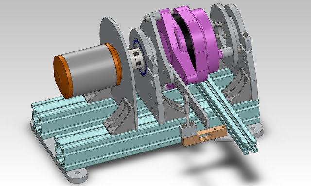
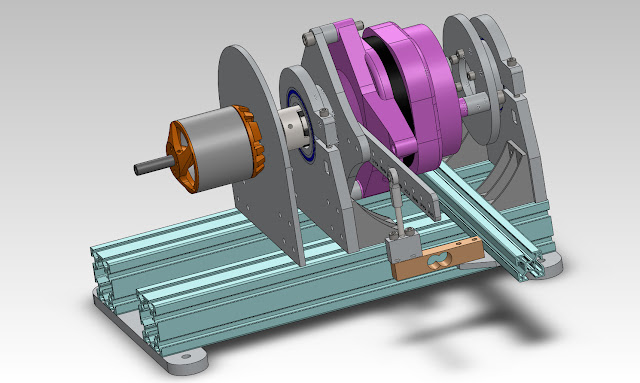
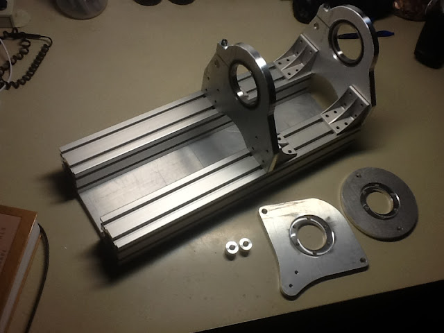
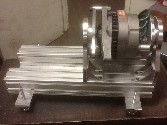
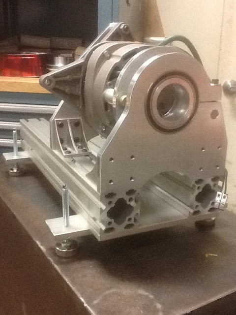
As you can see, an automobile alternator (in pink :lol: ) is used to absorb mechanical energy. The alternator is suspended on large-diameter thin-section bearings from vxb.com. A Love-joy coupler is used to couple to the motor under test. Aluminum structural extrusion from Misumi is used to support the various elements.
Why an alternator?

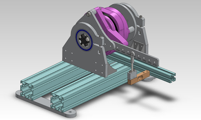
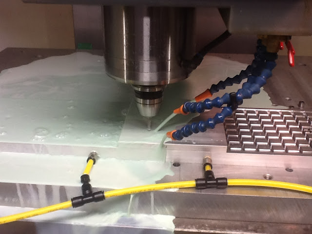
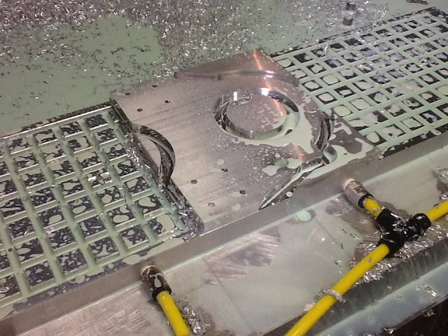
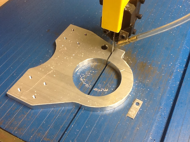
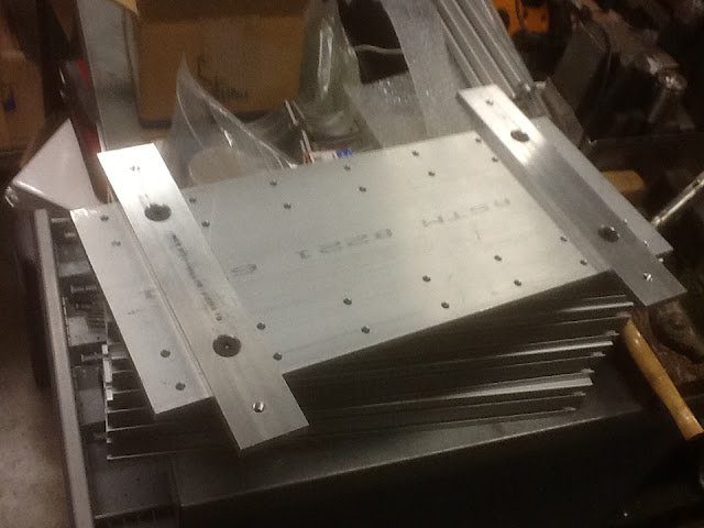
So- mechanically- the alternator is sandwiched between two plates which are bolted to the front and back using the pre-existing mounting features (with standoffs that are not pictured). These plates have a large center hole and bolt circle, which allows the "bearing boss" bushing piece to mount to it- this part will have a circle of tapped holes to match the mounting plate. The bearing will press over that boss piece and then be captured in another set of mounting plates front and back which are attached via 90 degree plates to the base extrusions. As you can probably guess the motor to test will be mounted on a similar plate and bolted to the extrusion via 90 degree plates. All the parts are aluminum, the outer plates are 1/2" thick, the inner plates are 3/8". The idea is to have the outside contours waterjet cut (I <3 WJ) and then finish-machine bearing bores etc. The rear inner mounting plate mirrors the shape of the rear end of the alternator- it will spaced far enough away so that a shroud could be attached and air forced through the alternator for cooling.
Alternators generally have an annoying semi-stubby, threaded, non-keyed shaft- in this design this can be dealt with once- in order to attach the Love-joy coupler, then any motor to test just needs the mating coupler. I imagine this will probably involve turning the bore of the coupler, keying or pinning the shaft of the alternator. The couplers are cheap, so it's no big deal to machine them to fit any given motor shaft.
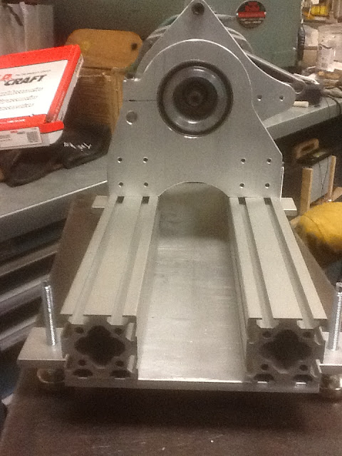
A load-cell will be attached to the reaction torque arm- the holes on the arm are 100mm, 125mm, 150mm, 175mm and 200mm from the centerline of the alternator shaft. I have some vauge ideas about a simple data capture system to send torque, speed, voltage and current information to a computer where they can be logged and analyzed.
I think I'll leave it there for the moment- please write if you have questions or comments! I've run this concept over several folks before, but I certainly will value the feedback of the community before I finish detailing the design and start manufacturing the parts!
Thanks!
-Henry
I've been thinking about a design for a compact table-top dynamometer suitable for testing ebike-scale motors for a LONG time- as I'm sure many of you have found yourselves, when thinking about motor and controller projects I always end up back at the need for a dyno to get real data about efficiency/power. As Fetcher's sig says "One test is worth a thousand opinions"-- and the "butt-dyno" is really just an opinion. :wink:
So, after going back and forth over ways to build something like this for ages I've come to this method- I finally sat down and roughly modeled the assembly yesterday. There are unfinished parts, and many missing parts, but it should be enough to get the concept across. I'm keen to hear your feedback if any particular aspect of the design makes an impression on you. I have given a lot of thought to the design and most of the choices have some sort of reasoning behind them- but I'm open to suggestions, and would be happy to elaborate on my thoughts as well.
As you can see, an automobile alternator (in pink :lol: ) is used to absorb mechanical energy. The alternator is suspended on large-diameter thin-section bearings from vxb.com. A Love-joy coupler is used to couple to the motor under test. Aluminum structural extrusion from Misumi is used to support the various elements.
Why an alternator?
- Cheap and easily available. This is a Delco Remy alternator used on some GM vehicles- I think maybe Northstar powered Cadillacs. There are tons of them available from junkyards, dismantlers or rebuilders.
- High RPM capable. Since they spin usually something like 2x crank speed they will see 10-12K rpm in service. The rotor is simple, rigid and monolithic.
- Electrical properties- externally controlled field strength. Essentially, I figure if you shorted the armature phases and drive the field it'll behave pretty much like an eddy current brake- but if you attach a fixed resistive load to the armature coils it'll provide a means to get part of the heat production out of the alternator- while the variable field still allows for torque control. I plan to build a 3-phase load bank using nichrome wire- another topic for another day- I think that picking a moderate resistance value for the load and driving maybe 0-20V on the field should allow for plenty of torque load flexibility across the RPM range needed for a given test- added bonus, if a 3-phase load is constructed it could be re-arranged in "star" or "delta" configuration to allow extra flexibility if necessary

- Home built eddy-current brake- not a very tough project, but likely to take more effort and cost to build. Also, depending on the size and design will not have the continuous power capability, since all the heat is concentrated within it (will need to be larger for a given power capacity)
- Commercial eddy current brake- I'm sure something industrial surplus would work great- but the supply is not consistant of these sorts of devices
- PM motor- in order to regulate torque the load resistor must change value- much harder to computer-automate than just the 20V/10A purely resistive field load.
- Inertial- An inertial flywheel is great and simple in concept- but can not measure continuous power (no good for thermal capacity tests) and it's harder than it seems to come up with a, say, 12", 25 lb flywheel system that isn't unduly scary, particularly at high speeds

- Water brake- the smallest water brake in current production I found was the Stuska XS-19 which I was quoted about $2k for, as well the torque capability becomes non-linear at speeds under about 2500 RPM- it's just not that well suited to this particular application- though sinking energy into water is indeed a good way to do it

- Friction brake- non-linear, hard to control, requires large mechanical setup to hold all the parts (disc, hub, caliper, shaft...), heat buildup
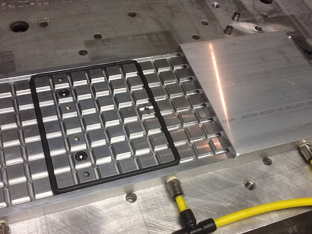
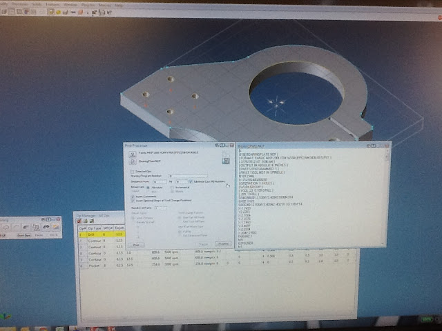
So- mechanically- the alternator is sandwiched between two plates which are bolted to the front and back using the pre-existing mounting features (with standoffs that are not pictured). These plates have a large center hole and bolt circle, which allows the "bearing boss" bushing piece to mount to it- this part will have a circle of tapped holes to match the mounting plate. The bearing will press over that boss piece and then be captured in another set of mounting plates front and back which are attached via 90 degree plates to the base extrusions. As you can probably guess the motor to test will be mounted on a similar plate and bolted to the extrusion via 90 degree plates. All the parts are aluminum, the outer plates are 1/2" thick, the inner plates are 3/8". The idea is to have the outside contours waterjet cut (I <3 WJ) and then finish-machine bearing bores etc. The rear inner mounting plate mirrors the shape of the rear end of the alternator- it will spaced far enough away so that a shroud could be attached and air forced through the alternator for cooling.
Alternators generally have an annoying semi-stubby, threaded, non-keyed shaft- in this design this can be dealt with once- in order to attach the Love-joy coupler, then any motor to test just needs the mating coupler. I imagine this will probably involve turning the bore of the coupler, keying or pinning the shaft of the alternator. The couplers are cheap, so it's no big deal to machine them to fit any given motor shaft.
A load-cell will be attached to the reaction torque arm- the holes on the arm are 100mm, 125mm, 150mm, 175mm and 200mm from the centerline of the alternator shaft. I have some vauge ideas about a simple data capture system to send torque, speed, voltage and current information to a computer where they can be logged and analyzed.
I think I'll leave it there for the moment- please write if you have questions or comments! I've run this concept over several folks before, but I certainly will value the feedback of the community before I finish detailing the design and start manufacturing the parts!
Thanks!
-Henry