Roadster E-Board Build (videos added 15/06/14)

daverobson08

100 W
Joined
Sep 27, 2013
Messages
115
Location
Blackpool, United Kingdom
Hi, like many here I am in the process of deciding what sort of eboard to build. I am fairly certain that I will be going for a single motor mountain board with a belt drive and custom clamp-style motor mount. I may well upgrade to two wheel drive if I feel I need it in the future :D

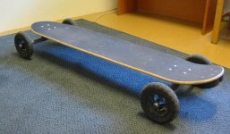
I hope to use the Scrub Psycho as a base:

scrubpsycho2.jpg


scrubpsycho2bottom.jpg


I plan to use:

2x Zippy Flightmax 8000 3s batteries (in series for 6s 8000mAh)
1x Turnigy 6374 190KV
1x 150A Car ESC (probably this one from Hobby King:http://www.hobbyking.com/hobbyking/..._150A_High_performance_Brushless_Car_ESC.html)
TX/RX: I am not sure yet but I may end up using a nunchuck with an arduino - this needs more thought

As far as the drive system goes, it looks like a lot of people are using chains for the MTB builds. I am going to go with a belt drive instead (let's hope this isn't doomed to fail!). Mounting the sprocket to the wheel hub shouldn't be too difficult. I have been dabbling with 3D design software and a small CNC at work (only 2D machining so far). My design is definitely not to scale and does not fit any particular wheel hub - it is just a rough mock up of the sort of thing I want to achieve for a 5 spoke wheel hub:

5_spoke_hub_pulley.png


When I get the mountain board ordered I can start to take some accurate measurements and recreate the model to fit. I will CNC some prototypes out of wood/plastic and then when I am sure it will fit then I can machine it in aluminium. I predict that the sprocket teeth will be the hardest part to get right :?

The motor mount will have to wait until I get my hands on the trucks. The stock trucks on the Scrub Psycho look to be fairly round unfortunately so will provide no keyway. I think I may have to swap them for these:

mbs_vectors_iso.jpg


mbs_vectors_detail.jpg


The MBS Vector trucks have a flattened hanger for grinding - perfect for stopping a motor mount from rotating! :D I will post up my motor mount mockups as soon as I can make them.

The only real concern I have at this stage is that I would love to mount the batteries/esc/motor/RX underneath the deck to give the cleaner look which the longboards have. I don't think I'll be going off-road so I'm not too fussed about damage in that respect but I'm still unsure as to whether I will have the clearance necessary. I don't think the batteries will get in the way since they are only 3s but the motor could be a problem. Has anyone tried mounting a 63mm motor under a mountain board? Am I living in cloud cuckoo land? I hope not!

Thank you to everyone on the ES forums - your trial and error has been invaluable and necessary to get the likes of myself to this stage. Hopefully others will be able to learn from my mistakes too! Any thoughts?
 
Awesome build. I like your idea of going the belt route. Definitely, interested to hear the results. I know that chains would be better for off-road rather than a belt. Good idea too on mounting something on the trucks with a non-rounded truck better for a motor mount.

Lucky you, you have access to a machine shop even if it is only 2D. Nice Drive Wheel COG as well.

I'm sure, you can put a case around the motor itself to prevent rocks/dirt/grime from entering the motor. I'd also get a custom fabricated box for your electronics underneath the board. It also looks like you can put some risers on the mountain board too, not sure how that will hold up though.

Looks like a great project though. Can't wait to see the motor mounts.
 
torqueboards - Cheers mate, I'll definitely check out the risers for the clearance. Regarding the box, I think I'll make an enclosure out of carbon fiber (again, this needs more thought!).

Progress on the motor mount/wheel hub design has slowed due to waiting for the wheel/trucks for taking measurements. In the mean time I have been ordering some fun stuff! Two Zippy 8000 3s LiPo batteries arrived today along with a cheap charger from Hobby King:

ge2S5kp.png


xEh4tIC.png


The cells are bigger than I expected, feel well made and a nice reassuring weight though! Unfortunately I was a little hasty in ordering the charger and I didn't realise that I wouldn't be able to charge both the battery packs at once (It will charge up to 6s but there is only one 3s JST connector) - I'm guessing this is probably standard. It's no problem though, I'll connect one pos and one neg of the batteries together and rewire the balance plug leads into a male 6s JST connector:

GmKM9y6.jpg


This should solve the problem, I'll be able to charge both batteries at once with the charger I have bought and will still have the slimness of 3s with the voltage and ease of charging of 6s (I hope).

While I wait for the trucks/wheels/JST connector, I have bought a couple of other goodies to keep me busy:

1uS3haw.png


F9nxSDD.png


arduino-pro-mini-328-5v-16mhz.jpg


Can you tell what it is yet? I'll post up progress as and when it happens!
 
Wow sweet build, looking forward to watching this happen. I just started mine but do to not having the skills or all the tools it will be a basic set up.. :roll:
 
I'm learning a lot as I go along here too! It's always tough learning something new - electronics isn't exactly my strong suit. Fortunately, a colleague and friend of mine is a bit of a tinkerer and has more expertise with this sort of stuff than me :)

I'm at the point where I am going to buy my ESC/motor now and I want to make some final checks. These are what I want to buy:

Turnigy 6374 190KV:
http://www.hobbyking.com/hobbyking/...roduct=18129&gclid=CJrslNjni7oCFTIQtAod-y8AEg

Hobby King 150A Car ESC:
http://www.hobbyking.com/hobbyking/..._150A_High_performance_Brushless_Car_ESC.html
[or]
Turnigy Trackstar 200A OPTO:
http://www.hobbyking.com/hobbyking/..._Scale_Sensorless_200amp_8s_Opto_Car_ESC.html

Potential problems:
  • I currently have 2x 3s which I will wire in series for 6s (22.2v) - will this be enough to power the ESC and motor? (and me!)
  • I have considered adding another 3s pack in the future so I will have 9s (33.3v). Will this be too much for the motor/ESC?

I have spent a good while reading this forum and this instructable (VERY helpful) but it is still a little difficult to get my head around some things! Especially when the stated max inputs/outputs etc never seem to be what you can actually use!
 
Be careful when going over 6s. Everything starts to get more expensive form that point. I got 8s lipo's, needed a different charger, motor has to be able to handle it, ESC as well (!). It's considered HV (high voltage) in this sector.
 
Murfix - Yeah I remember reading somewhere here that was the case. How much did your charger set you back? I had wondered whether I could charge my batteries in two batches (3s and 6s)? Do you find that 8s gives you a lot more power? I notice you are using a dual motor setup (Very nice build btw - those mounts are a really nice solution) - did you go down the 8s route because of this?
 
You can charge your batteries in parallel with your charger - making a 3s 16,000Mah battery - then you can either ignore the balance leads, or for when you want to occasionally balance charger (you really don't have to do it often, if ever!) - This kind of thing:

http://www.ebay.co.uk/itm/6-in-1-Parallel-Expansion-Board-Battery-Charger-for-Imax-Balance-B6-B8-Charger-/270996078734?pt=UK_ToysGames_RadioControlled_JN&hash=item3f18a0008e

Hobbyking sell them too. Or just this:

http://www.ebay.co.uk/itm/XT60-Parallel-Adapter-Harness-Connector-Converter-/370728900321?pt=UK_ToysGames_RadioControlled_JN&hash=item56512a16e1

The balance board actually works out kind of handy for other charging uses, and a giant balance adapter!

8S gives you more voltage, which = more top speed, or, more duration. I'm running 6S and people running the same speed as me but on 8s are getting longer range. As correctly pointed out, your expense goes up a fair whack once you pass the 6S mark - in terms of ESC and charger.
 
- I went down the 8s road mostly because people were saying 6s was perfect for longboard/skateboard assemblies while I was going for a MTB with the ability to go off road (and yes, dual setup played a part in my decision as well). However, I thought the 8s ESC from Alien could handle fully charged 8s batteries, but this isn't the case, so I rewired my batteries to 7s.
- In essence, more cells don't give you more power, but more top speed. I'm not looking for more top speed, so I could change my gearing to get more torque and the same top speed. So in practice, yes, more cells can result in more torque.
- I didn't compare to a 6s setup, so I don't know how much better it is, but I do know this: I can't go much higher in gearing ratio, because the sprockets will be larger than my wheels... so there's my limit. I'm currently using 45/8 teeth, so 5.625:1 reduction.
- I also wanted a much higher range than most builds on here. My single commuting distance is 12km. I used 3 5800mAh packs, but it's overkill! I could ride back and forth to work on a single charge (I can charge at work so that's not needed).

-To answer your first question: I was impressed by the amount of exploded-lipo-experiences shared online and by how tender they are, so I invested in a good quality 8s charger (only up to 8s). It cost me 118$ (iCharger 208b form Hobbyking). It might have been overkill, but it works as expected. In your case, I would try 6S first and see from there. 8s is more expensive, but 9s is yet another ball park.

Thanks for the feedback on my mounts! ^^
 
I've never had a lipo fire. I've had packs swell at worst. You pretty much have to abuse them to get an "exciting result". Do protect them though, they are squidgey!

You only have to read the dumb questions that some people ask on other forums to understand what gene pool is out there charging batteries ;-P - I'm guessing most fires are down to people charging 3s packs at 4s etc. or ignoring hot puffy packs and whacking them back on charge.

I lie - I've had one lipo "fire" - but it was on purpose. I needed to get rid of a dead pack , and I have an air rifle :) - it took about 4 shots though!

http://www.youtube.com/watch?v=ys5yZfK0rv8
 
RogerD - Those parallel balance boards look pretty handy, maybe I could hack one of those up to use for an all in one charging solution. It would be brilliant to be able to have just one plug for charging. Perhaps complication is the nature of the beast when it comes to LiPos. It's nice to know that balancing isn't as crucial as I have been led to believe though. That video doesn't reassure me too much! :lol:

Murfix - That's a shame about the Alien ESC. I bet you were pretty disappointed! I think my daily needs for getting to work and back would be around 4.5mi/7.2km (although I could probably charge at work). Hopefully with 8000mAh cells I should be okay though. It sounds like I should steer away from higher numbers of cells after all, there's no point adding too much complexity or cost at this early stage, I have enough to think about!

This morning the wii nunchuck and my test wheel arrived:

IwKj8gD.png


Now I can dust off the callipers and start to take some proper measurements! First looks at the wheel make me think that over engineering a hub is possibly a silly idea. There are already 5 allen bolts which run through the entire piece (It comes in two halves - presumably for ease of fitting the tube and tyre). I'm pretty sure these could be replaced with longer bolts and utilised more simply. I'll have to wait for the wiichuck adapter and the arduino before I can delve into the TX/RX. I couldn't resist gutting the receiver though. My fingers are getting itchy!
 
Hey man,

I've got the same system for my wheels (2 halves with 5 bolts). I replaced the 5 bolts with longer ones like you are thinking about, and placed the sprocket on those with locking nuts. Works perfectly. Yes, I was very disappointed, but after testing it out, I was all happy again! The system is awesome and more than powerful enough for me!

About parallel charging: you can charge all lipos in parallel as long as they have the same amount of cells (and the same voltage per cell). I created a custom parallel lead. I can't balance 3 batteries at the same time at cell level, but with 3 batteries, I can balance per 3 cells...
r42u.jpg

69h6.jpg
 
That's a nifty little adapter you have made, I'm thinking if I stick with 6s that I won't need it though. The main problem is going to be the ease of charging for me. Hopefully I will be able to work out a way to easily isolate the batteries from the rest of the circuit without having to open up the internals every time. I think this will work:
untitled-2.png

(The receiver/arduino and balancing leads to the batteries are not pictured to make things simpler)

In position 1, the 'key' is inserted into the left and middle plug, completing the circuit for running the board. In position 2, the power leads from the charger are inserted, isolating the batteries from the other components. I will have to plug the balancing leads in too but at least now there are just two things to plug in for charging. I won't have to take the cover off the internals or buy a high amperage switch/relay. I have stolen the idea for the 'key' from you Murfix, thanks for the tip!
 
That's not stolen, btw it wasn't my original idea either :) It works well though. If you're not working with a switch, you have to keep in mind that you will have a spark in your key every time you plug it in. It's not that bad, but your plug contacts will wear out faster. I hope you can fit everything under the board. I didn't do that because my board is very flexible and when doing bumpy rides, my bats would hit the ground for sure =/ And you're right, with 2 3S in series, you got no charging problem if you make the 7pin connector right.
 
Yeah it seems like the best option I can go with. Although I think I may need a switch in the loop somewhere in the form of a foot pedal to arm the device. The Arduino/Wireless Wii nunchuck is a little bit flaky and I'd like to know that if I fell off the board it would stop! Here is how the controller is working so far:

http://www.youtube.com/watch?v=ADaCzcvzsCo

(apologies for the portrait orientation, this was sent via mobile and was only intended to be viewed that way. Hopefully you can get the idea)

As far as we understand, controlling a brushless ESC is akin to controlling a servo. The servo position corresponds to the amount of power that the ESC provides:

uVFZyiB.png


The ESC receives no throttle signal by default. The throttle is armed by pressing and holding the Z button (trigger button) on the nunchuck. The speed is then controlled by flicking the thumbstick upwards or downwards. There are three speed states ranging up to 100%. When stepping up a speed, the transition is staggered over four increments. When stepping down a speed, the transition is instant. To the best of our knowledge, we are only controlling the throttle input for the ESC and we cannot work out how to provide a reverse/brake input. Would this be a signal in the range of 180-360°? It would be handy if anyone else has tackled this already who could shed some light on the situation!
 
Here is the rough idea for the motor mount. My trucks still haven't arrived so I can't make anything more precise yet. Note that the trucks have a mounting point for braking systems - the motor mount will bolt through this. Hopefully you can get the idea from my primitive SketchUp skills! :lol: I've pictured it from a few angles both with and without the truck hanger:

leq6NY3.png


Theoretically this can be cut out of a single sheet of steel/aluminium. I think 4mm or 5mm should be thick enough to stop twisting. I don't have access to a sheet metal brake so I will have to do the bending with a vice/jig setup. This is the only bit that I can see being difficult.
 
Seems to me that you won't have any options to tension the chain/belt. Some elongated holes could do the trick. Otherwise very nice!
 
More parts are on their way! I have ordered the follwing:

Toro TS 150A ESC (£65.00 from UK)

01.jpg

http://www.skyrc.com/index.php?route=product/product&path=18&product_id=178

+ SkyRC Bluetooth Module (£13.71 from China - for programming the ESC via Android/iPhone)

12.jpg


Turnigy SK3 6374-192kv (£56.39 from UK)

$T2eC16JHJIUFHHkJoB46BR0pfsYdDw~~60_12.JPG

http://www.hobbyking.com/hobbyking/store/uh_viewItem.asp?idProduct=18129

Once the bluetooth programming module for the ESC has arrived, I can make some more headway with the nunchuck/arduino controller. Hopefully the ESC will do the job. It is a little smaller than the HobbyWing/HobbyKing equivalents so it will have less of a footprint but it remains to be seen whether it has the cooling capabilities needed. I haven't seen anyone using it so far as I think it is fairly new to the market.
 
We've been fairly busy at work with designing/building a laser cutter so I haven't had much time for personal stuff. Nevertheless, some more parts have been ordered and arrived so I'll sum up where I'm at so far.

The ESC and Motor have arrived. (Bluetooth programming module is still on it's way from China):

SOE2G8j.png


h9RohXK.png


8qpsh3P.png


oIwEnHT.png


The SK3 is beautiful! Really reassuringly heavy and the windings don't look too bad either -there is plenty of copper in these motors! Even knowing the dimensions before ordering, upon arrival this was bigger than I was expecting. Without having tested anything yet, first impressions are good.

The blue ESC casing is plastic and not metal as I had naively assumed from the pictures when ordering. The whole thing doesn't exactly scream quality but I am quite willing to be disproved! It's pretty small and shouldn't be hard to find a home for on my board. Let's hope it's up to the job. I'll be able to test it when the programming module arrives.

Next on the arrivals list was the drive mechanism. I have abandoned the custom hub insert, realising that it is literally reinventing the wheel and totally unnecessary in my situation. I will simply bolt the pulley to the hub using the existing screw holes in the hub. Ordered from the US (https://sdp-si.com, cost was roughly $55 (£34). Shipping was $98 (£60) but I did foolishly request UPS Express 1-2 day delivery. On top of that, I was stiffed on the Duty and Handling Fee (£25). Total cost: £119 :shock: Ah well, lesson learnt! I'm sure if you live in the US or can find a decent domestic/local supplier then this becomes far more reasonable.

aEtNWvI.png


Segkb0j.png


fGtmk2t.png


The large wheel pulley has 60 teeth (outer diameter = 94mm) and the smaller motor pulley has 17 teeth (outer diameter = 25mm (not including flanges)). The motor pulley is bored to 8mm with two grub screws and fits the motor perfectly. As well as the pulleys I received a 73 teeth 15mm HTD belt with 5mm pitch. The motor will sit pretty close to the wheel and should keep the setup as compact as possible. I cannot fault SDP/SI on their service - the parts are finished very well and of the highest quality I could have expected, I highly recommend them. I'm sure it has been mentioned before but there is a resource on their website which lets you calculate pulley sizes, ratios, centre distances, etc. (https://sdp-si.com/eStore/CenterDistanceDesigner). It then offers you products which suit that requirement in situ. This tool was invaluable in deciding what size pulleys to use and I would urge anybody struggling to work out what to order to look at this.

Here is the wheel pulley with the five spoke wheel hub for comparison:

twSx1MI.png


9nPbZ3q.png


As you can see, I will have to drill holes through the pulley to accommodate bolts running through the wheel hub. In addition to this I will have to remove a large portion from the centre of the pulley. It will be a shame to butcher this beautiful part but it will need to spin around the axle and unfortunately it definitely won't fit as it is now! I don't have access to a lathe so this part will be difficult. Here is an illustration of the problem:

VpAuX1L.png


You can see here one of the trucks which arrived. They cost £25 second hand off eBay:

982rvJ6.png


0miQan6.png


5DWsCaA.png


The motor mount which I posted earlier in the thread is quite probably not going to be done. I have been offered the services of a welder and the more I think about it, the better this seems. A single plate welded around the axle will be far easier to design and probably stronger. I would have loved to use the shape of the truck and the threaded hole to secure the mount but in all honesty, without a sheet metal brake, the bends would be too difficult to get the accuracy needed for this application.

I have been toying with the idea of making the housing for the electronics out of carbon fibre. The ESC and the Arduino/RX would be in one housing and the batteries would be in another separate easily removable housing. Here is a video from a supplier of carbon fiber kits: http://www.youtube.com/watch?v=IAdVO8Rkv6c. I'm pretty sure this would be the perfect solution both in terms of practicality and aesthetics.
 
Thank you. I am feeling a little less happy with the size of the mountain board deck and would prefer something smaller for daily use. If I could keep the MTB wheels whilst having a smaller footprint overall, that would be great. This is the idea I came up with:

z0EC5Nc.png


Pictured top is the Scrub Psycho (my original basis for conversion).
Pictured bottom is my proposal (right hand side with possible cutouts)

Issues I can see immediately:

-Strength. With cutouts for the wheels/motor, there is considerably less wood and I worry that this could lead to snapping. If I could find a carbon composite street deck then this should be no problem. With plywood, I am not so sure!

-Handling. I haven't seen anyone having done this yet. There some cheaper Chinese eMTBs with wooden decks but the trucks are mounted in the usual place and not on the nose/tail. Would this have a detrimental affect?

Does anyone have any input on this matter?
 
if u mount the trucks on the tails of the street deck, there's good chance of ur feet hitting the wheels when turning,
ur vector trucks are not ideal for top mount, would need lots of wedging.

these cheap ebay drop down decks might be a bit shorter than ur scrub deck,

http://www.ebay.com/itm/Carve-one-Natural-Blank-Drop-Down-Downhill-Freeride-Longboard-Deck-41-/231017067910?pt=LH_DefaultDomain_0&hash=item35c9b0b586


this is a top mount setup with skike wheels (smaller)
good for a smaller setup

http://endless-sphere.com/forums/viewtopic.php?f=35&t=49924&p=738041&hilit=skike#p738041
 

Attachments

  • setup by whalebone on skike wheels.jpg
    setup by whalebone on skike wheels.jpg
    62.7 KB · Views: 13,268
Thanks for the thoughts sk8norcal, some really good info there. I hadn't considered the wheels getting in the way of my feet but now you mention it you're probably right. Especially given that my rear foot would be on the tail.

I'll definitely look into a longboard drop down deck too - that looks like I really good solution. I would feel more confident having a deck already cut instead of butchering one myself too!

Those wheels look perfect! Pretty expensive though. Looks like the best I can find is $100 (+shipping to the UK :( ) MBS sell these ones:
urethane_wheel_set.jpg

http://shop.mbs.com/accessories-14/...complete-wheels/urethane-wheel-set-145mm.html
They are solid urethane though which isn't what I had in mind really. Perhaps I can find some cheaper wheels with pneumatic tires.
 
Cheapest new pneumatic wheels I found was around 20-25$ for rim + tire, so yeah 100$...
You can try ebay or maybe 2nd hand if you only need 1 set of 4...
 
Back
Top