GT's Curious Custom build

gtadmin

10 kW
Joined
Aug 7, 2009
Messages
744
Location
Whyalla South Australia
Intro (Damn the server "upgrade" that removed all the photos :evil: )

Hi Guys

I've been riding an ebike since 2006 (though not lately), in this case a Aprilia Enjoy with a limit of 250W driving through the bottom bracket. One of the drawbacks with this bike (besides the battery which is another story) is the lack of power when going up hills on a windy day. Where I live, that is every day. Other environmental factors include summer temperatures upto 48oC in the shade.

I considered how to reduce the effect of the wind, and the only ways that I think are valid are to reduce the frontal area or use streamlining. I don't consider streamlining to fit into the "bicycle" category, so reducing the frontal area is it ie some sort of e-recumbent. I had a look at a lot of the current designs, and the only one I thought looked reasonable was the XR2, or groundhugger. However, this has some design problems to overcome. I drew up some sketches, but that's all that happened until I saw AussieJester's (KiM) cruiser's build.

I thought if this guy who doesn't have use of his legs can take on that project, I can build my recumbent! And so that was the beginning of this build.

Current Status
This section will display the latest photos of the bike (Dec 2011 here).

20111208.jpg


Beginings (Feb 2010)
These are photos of the "junk" that would be used to build the frame.
1Junk1.jpg

1junk2.jpg

1junk3.jpg


Placeholders for links to the posts as they are discussed
Electric parts (Feb 2010) - next, Rear frame, Rear dropouts, Frame, Seat, Front dropouts, Forks & triple tree, "Tank" Head tube triangulation, Rear disk brake, Drive train, Batteries
 
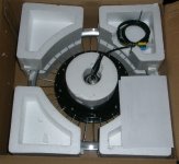
I chose to use an electro-magnetic brake, unkindly called a "frock" motor by some demented people. :lol:

There are three reasons for this choice:

  • I don't need a lot of power (torque, yes) as I don't expect to go that fast (although this may change),
    I don't want a lot of noise (the Aprilia has attracted some"unwanted" attention) and
    I don't want to use a gearbox I didn't make!
An outrunner seems overkill for this! Found a 9C FH205 on sale from ebike-kit.com for a reasonable price laced to a 20" rim. Don't know the winding (7x9?) and I assume is the same as a 2805.

Bought a 35A modded controller from Justin at ebike.ca, along with a thumb throttle (subsequently pinched for the Aprilia so I need to order another), metal brake levers with hall switches and a direct connect CA.

Once I had made this financial commitment, there was no turning back! Now I had to do something!

20100222_frock.jpg
Edit: photo added
 
Well I had most of the electrical parts, but no design other than it should be low, and no longer than 2m overall (as I have to get it through a turnstile). I was at the newsagent and spotted a magazine called "Street Machine - World's wildest choppers (Issue #5)". On the cover is a bike called "Red Dawn" which looks like a big, red arch. There's an ebike I've seen on the forum (can't remember the name) which looks as if the designer has just copied Red Dawn, but as a bicycle. Quite expensive too!

Anyways, I bought the mag and there were some really nice design features on some of the bikes that I thought I'd like to implement, one of them had big upswept pipes at the rear which looked like exhausts but were actually the rear forks. Here is the link: pipe bike but the website is down as I write this!!

Here's my version:


The pipe I used was 38 dia 1.2 wall thickness (the legs of the bedhead). I tried bending them with a pipe bender but all that happened was it kinked. To get the compound bends, I had to slot the tube, bend it, weld it and add gussets. Took me a couple of goes to get the shape I wanted, all done by "eye". I added a telltale right at the "Y" join (underneath)
 
Time to manufacture the rear dropouts! Bought some 6mm plate 75 wide 1m long for $10. Made a template from cardboard, scribed it to the metal, centre-popped it around the perimeter and where I wanted to drill. Drilled the holes with a 9.5mm drill, then cut the dropout out with a cutting disk. Of course, cutting with a friction disk blues the metal, and any scribing is lost. That's what the centre-pops are for! Once that was done, I used my CNC machine (commonly called a bastard file) to accurately "machine" the slots for the axle and the outer shape.

As usual, here are the pics.
20100502_rear_do_1.jpg
 
Looking good there gtadmin i'm still lovein' that 'trestle' work on the
top tube, the large rear wheel doesn't seem to look as 'prominent' now
does it..

*subscribed! & look forward to the next update, keep up the good work, she's
looking very sharp thus far ;)

KiM

EDiT: meant to add..when you get it to the 'rolling' stage like you have now,
it gives you a lil extra drive and motivation to keep going... Does for me anywayz... haha
 
Thanks for all the kind comments guys. bzh, prior discussion of triangulation here

AJ, yes the large wheel doesn't look as prominent now but I'm half considering going to a 20 inch, but that would make the bike really tiny, and I would need some sort gearbox to get the gearing I want. Picture the old fart (I mean "experienced gentleman") on this, with my Aprilia in the background for sizing purposes. BTW, I'm 174 cm tall (or 5' 8 1/2" for those people who are still using last century's measuring units :lol: )

20101016_size.jpg

BTW, found the red-arch bike here, and the original scanned from the magazine mentioned above is here (with three cool looking Spanish guys):
red_dawn.jpg


Now where was I?

I found the bike that was the main inspiration for my design on this website - sugarland express.

Now that I had a design, at least in my head, I needed to make some sort of rudimentary jig. I had some fence railing (sized 38 x 25 mm) and I used this to create a couple of side-by-side rails spaced 65 mm apart. At each end, I welded on a piece of railing about 600 mm long to form a giant capital "I". At each end of each crosspiece, I drilled some 12 mm holes and had some threaded rods with nuts which allows me to vary the height of each corner ensuring that the jig is flat.

I had some 65 mm pine laying around so I cut two pieces about 400 mm long, drilled one with a hole 330 mm from the end and the other with a hole 250 mm from the end. Through these holes I put some 10 mm diameter threaded rod with nuts and washers and these acted as axles. I was then able to set up the back end and attached the dropouts to the frame with two tacks on each dropout.

I then placed some cardboard at the back and sketched up how I would like the frame to look, and proceeded to bend some pipe to the shape I sketched. Unfortunately, I had the same problem that I had with the larger pipe in that it just wanted to kink. The solution was to use some of the prebent tubing from the tables pictured in junk 3. This tubing is 25 mm in diameter with a wall thickness of 1.2 mm.
20100509_mockup.jpg
 
The head tube was cut from the bike frame in junk 3 and cleaned up. Two pieces of 25 mm diameter tubing approximately 20 mm long shaped to fit were then welded between the mainframe and the head tube approximately 75 mm apart. Once the alignment was checked, it was plated with 1.6 mm thick sheet steel and fully welded. The welds were cleaned up with a flap disc then filed to give me a witness. Yeah, goose-necked!

The bottom bracket was cut out of the frame in junk 1, cleaned up, holes filled, cleaned up with a flap disc and again filed to give me a witness. Basically the same process AJ used with his cruiser except that I didn't extend the width of the bottom bracket.
20100530_goose_neck.jpg
 
Hi guys,

It was now time to join the 25 mm tube to the 38 mm tube underneath the bike. This was done by cutting a slot in the 38 mm tube about 10 mm wide and 40 mm long, and the 25 mm tube was inserted and placed hard up against the slot. (The slot was at the top of the tube.)

Once the alignment was checked with the front downtube, the edges of the top slot were welded to the 25 mm tube. About eight slots were then cut in the 38 mm tube equally spaced around the perimeter, each of them were about 3 mm wide and 40 mm long. Each tab formed by this process was bent down one at a time to touch the 25 mm tube and welded in place. Once all tabs had been bent and welded, each side of each tab was then fully welded.

All the welds were then cleaned up with a disk grinder, and then re-welded again. This process was repeated until such time that I had achieved a smooth, round taper that was also strong.

One thing to note is that all joins in the 25 mm tube have an inner sleeve inserted 10 mm on both sides of the joint and welded in place before the tubes were weld-prepped and welded.

While this was happening, I ordered some parts from Chain Reaction Cycles:

Schwalbe Big Apple tyre - Kevlar guard 20 by 2.0
Schwalbe Big Apple tyre - Kevlar guard 26 by 2.0
Mavic XM317 disk brake compatible 26" rim, 36h
Shimano Disk Hub Rear M475 36h black 6-bolt
Avid BB7 mechanical disk brake
Schwalbe tubes
ControlTech rim tape
Stainless steel spokes

These eventually arrived (delayed due to the Big Apples not being available) 20100630
 
Now that I had my tyres and knew exactly how much room I had, I was able to set up the seat. Because the bike doesn't have any suspension, I wanted to have a sprung seat. I used the spring from the frame pictured in junk3, and the smaller mounting bracket. I used one of the bookends displayed in the following photograph and panel-beated it to form the base of the seat.

It took me a little while to get the shape that I wanted, and in the meantime I opened this topic in the technical section "Framebuilders -how much trial do you use?". While this discussion was occurring, I still continued on with the base of the seat. The base was reinforced with 3 mm x 75 mm wide plate through the centre, shaped to suit. The pivot at the front of the seat was formed using 10 mm internal diameter tubing.


It was now time to build my front dropouts, which like most parts of this bike are unconventional :!:
 
file.php


Solid seat, make sure you wind the spring tension up on the 'shock' though or it will be stiff
(unless your 300lb?) I used a mini spring from a tiny kids bike on my seat and im a "beefcake"
type and it wouldn't move un-tensioned, wound him down shes niiice when i hit them lil bumps now.

KiM
 
AJ said:
Solid seat, make sure you wind the spring tension up on the 'shock' though or it will be stiff (unless your 300lb?) I used a mini spring from a tiny kids bike on my seat and im a "beefcake" type and it wouldn't move un-tensioned, wound him down shes niiice when i hit them lil bumps now.
I don't want the seat base to fail and have a coil over shock shoved up my ar ... err ... rectum :shock: , because that certainly would :lol: . The spring unit pictured came off a boy's bike and it's wound until the slack is just taken up. We'll see how it goes once I'm powered, but I'm getting 6 mm of movement now and I weigh 62 or 63kg (around 140lbs), depending on the day. Also, I have 25 mm high density foam to cover the base which will make it even more comfy.

Cheers mate for the tip :wink:
 
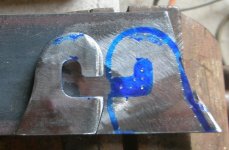
After reading a lot of posts on front wheel drive hubbies and how dangerous they can be if it is not done correctly, I used 6 mm thick steel plate for the dropouts (even though this build will be relatively low powered). I drilled several 9.5 mm holes to form a slot and then filed the slot to 10 mm wide until it was a neat fit to the axle. I also filed the corners to approximately 14 mm diameter. This, and the torque washers supplied with the ebike-kit, should be enough to prevent any spin.

Then I got to thinking, what if the axle did spin and the dropouts did spread, what would prevent the wheel from falling out?

Solution :idea: : I cut a piece of 3 mm thick plate and drilled a hole the same diameter as the torque washers (actually a series of very small holes and filed it round) with a 10 mm slot at the bottom, and placed this over the other plate I'd already made. I then tack welded the two plates together, drilled 4 holes 5 mm dia and countersunk the holes with a 8 mm drill. This is as pictured top left. Each of the holes were tapped out to 6 mm, a piece of threaded rod screwed in and trimmed with about 4 mm protruding on each side. Each of these rods was then riveted over with a ball pene hammer, shown in part in the bottom left picture. The nut is there so I could cut the rod without it spinning. Once this had been done, all the "rivets" were filed flat.

The top and the two sides were weld-prepped, and fully welded. Ain't nothing going to move here baby!

20100828_fdo_3c.jpg
 
Hell yeah haha..looks like i wasn't the only one cutting some serious metal plate today ;)
nice work mate, 'dat'll hold da frock ;) I would think shes not far off her first scoot about to see if everything woks?
Look forward to next progress report...all the best with the continued fabrication :)

KiM
 
G'day AJ, nah mate, these were done towards the end of August when the other thread was still active. I'm trying to fast forward through this build log until I get to the point where I left off on that thread. I haven't done much with this bike since then because I was working on the Aprilia, fibreglassing up the battery case, and you know that welding and fibreglassing don't go together! I'm pretty cautious about this sort of thing nowadays as I almost burnt my house down in the middle of January – $7200 worth of damage :oops: Long story but!

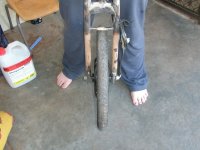
I call them suspenders – they're there to hold the frock up :lol: Here's a photo of my granddaughter holding the front tyre 100 millimetres off the ground with both axle nuts fully unwound. Not that they would ever get to this stage in real life.

20101015.jpg
Cheers,
GT
 
GT said:
johnrobholmes said:
Nice! Thats a funny shaped dropout.

Curious even

Because of the style of the bike, there will be no kerb hopping etc. Therefore, even if there were no nuts on the axle holding it in place, it will still stay in alignment (well mostly)

Cheers,
GT
Just to expand on the design of the rear dropouts, these are a combination of vertical and horizontal dropouts. Why? Primarily, accurate location of the axle, but also failsafe design and ease of use.

The best form of axle location would be a "neat fit" hole sized to the axle, but this involves using a through axle which is not a normal bicycle design and therefore unsuitable. Horizontal dropouts are used when there is no form of chain tensioning, the dropout is the adjustment! But what a pain in the bum to get everything aligned properly! BTW, this is normally used when there is only 1 sprocket involved. When there is some form of chain tensioning ie a derailleur, vertical dropouts are normally employed because they locate the axle accurately and there just is no requirement for horizontal adjustment. However, I couldn't use pure vertical dropouts because of the frame members existing below the axle ie the pipes, so a combination was the logical choice.

Of course, if I were to make another bike the design of these would change slightly.

jrh, I apoligise for any perceived abruptness of my previous post if this is the info you required :oops:

Cheers,
GT
 
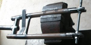
Once the amount of trail had been determined (in the "Framebuilders" thread), I set about building the front forks. Two 380 mm lengths of 25 mm tubing were used to build these. A slot 9 mm wide and 30 mm long were cut in one end of each tube and the dropouts previously manufactured were inserted, positioned and tack welded in the slot, in one spot only. (The slots were cut using a hacksaw and filed to size.)

The fork legs were then attached to the frock motor, and aligned with each other. A short length of 14 mm tubing was tack welded between the two legs keeping them in alignment. The forks were then removed from the motor and a second tack was added to the dropouts, replaced back on the motor and checked for alignment, removed again and fully welded.

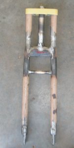
The head stem and fork assembly from the bike in junk1 were used. I cut off the (rooted) front suspension tubes, leaving the head stem and the two outriggers. These turned out to be too short and the fork legs had to bent slightly inwards to close up the gaps. The fork assembly was mounted in the rudimentary jig taking care to ensure 30 mm of trail would be used, and the tops of the fork legs were tacked to the outriggers, 2 tacks on each fork leg. The frame was then taken out of the jig and all parts were assembled. MOBILE at last :evil: Time to test the low speed handling as this was the most concerning to me (I'm not concerned about higher speed handling - that will be fine).

A quick scoot around the backyard confirmed that low speed handling is excellent, flop is minimal and pushing the bike by the seat at around 10kph confirmed it tracked dead straight. SUCCESS :D :D

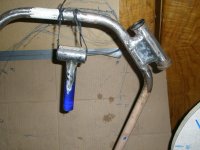
The fork legs were then fully welded to the outriggers, and not trusting the Chinese robot welding, a gusset made from 3 mm thick 25 mm wide flat was bent to the right shape and fully welded in place. Once this had been done, the frame was reassembled again and assessed: geez that looks a bit odd! To add a bit more strength and fix the odd "look", the fork legs were extended to the top of the head stem (using sleeving ...) and an upper triple-tree was manufactured.

20100911_fork_brace.jpg

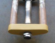
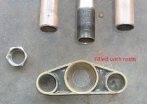
A trip to the local steel supplier saw me score some tubing that slid relatively easy over the 25 mm tube. Also scored was tubing that slid easily over the upper steering bearing race. These tubes 20 mm long were positioned on a piece of 3 mm thick flat and tack welded into place. A hole was drilled and filed for the threaded part of the head stem to poke through, everything was checked for alignment and fully welded. To add strength to the plate, 3 mm flat was welded tangentially between all the tubes and the welds were cleaned up. Ta da, a triple-tree!

Provided the welds were not cocky-shit (and they're not), this assembly will never break. With the benefit of hindsight, I would make these slightly different next time.

20100920_oa.jpg
20100920_tt_top.jpg
20100920_tt_bottom.jpg

Still to do: clean up the welds. Remove the 14 mm brace and make a new one that doubles as a cantilever brake mount (this one's 50/50)

Cheers,
GT
 
Back
Top