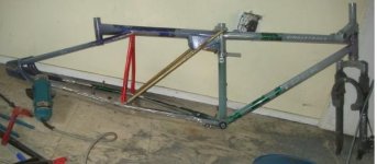
Amberwolf's Bolt-Together Semi-Recumbent Cargo Bike

Sorry, bottom sketch is just an angle view of the swingarm/etc, to show how it attaches to the BB/frame. Springs were left out so the rest would be visible; it all is the same as the top sketch.

I could do this swingarm one of two ways:
A) fixed bolt/pivot at each end of spring, doesnt' slide but only bows upward in center.
B) Fixed bolt at one end (front?) with slide pivot at other end (easiest at rear), not sure if that would even do anything in this design.
Which would probably work better?
If possible, I'd certainly prefer to build the swingarm/leaf one of the above ways, rather than the one below.

I came up with another method of using the leaf spring with the existing stuff previously sketched:

Would this one work, assuming my cargo pod frame (orange) is stiff enough?

Bike frame is all black, and would be welded as one piece. Cargo frame is orange, welded to bike frame along intersections with black frame visible.

Leaf spring is green, with it's pivot at rear of cargo frame, and the slide bracket (Ubolt of some type) onto the cargo frame.

Swingarm (swing frame) is red, and it pushes against the center of the leaf spring at it's axle, upwards. For now I'd leave it as the whole swing frame to test the idea, then build one just for this purpose if it works under the cargo loads I'd like this to haul (up to at least a couple hundred pounds in addtion to the bike's and my weight).

I guess one advantage of this way is that all the cargo weigth is directly transferred to the wheel, rather than via the bike frame. But it also means that the bike weight (and mine) has to go thru the cargo frame, and leverages against the cargoframe/bikeframe joins. Most of the time there won't be much on the cargo frame.
 
Yes. That latest design would be fine. You will need to find out what weight you can put on the 2 springs, to see if it will be too stiff or too soft.

What about a shock to take the pogo effect out with more cargo weight ??
 
I have some dampers from powerchairs that may help with the latter.

The leaf springs I might be getting are from a trailer kit that has a bed that by itself probably weighs 50-100lbs, plus cargo capability of probably 500-1000lbs, maybe more. So with two leaf springs, it'd be too much. I'd like to figure out a way to use just one (which is why I wanted to use it forward of the swingframe, instead of beside it/above it).

I did think of a way, but it would add a lot of complication.
LEAF SPRING IDEA 3A.JPG
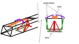
Basically the leaf (ORANGE) would wind up upside down over the top of the tire, a bit above whereever the limit of swing would be. Then a rod (GREEN) comes up from either side of the axle (GRAY), pushing on the outer end of a lever (PURPLE) whose pivot point is mounted on the cargo frame (BLACK). The inner end of that lever pushes downward on the center of the leaf spring, effectively transferring the vertical upward load from the axle into a downward load onto the spring.

Does that make any sense?

I'm not sure that it would work, and given the extra complications it may not even be worth trying. But if I could make the levers compact enough and keep it all inside the frame (unlike in the drawing), it would help to leave all of my cargo frame free and flat on top for stuff. :)

Also, like MichaelPlogue's design, it would act as a fender to keep road crud off of me and my stuff. ;)


I guess another way to use it would be pretty much like he did, with the normally sliding end fixed in place forward of the swing frame, angled upward and backward as if it were a fender, to arch over the tire. Then put the green rods I have in the above design from the axle to the pivot point on the leaf spring. It would then just bow back and forth, instead of the usual method.
 
The image 4A looks good. Flexing the spring from one end will give more action than flexing in the middle. Fasten the flat end and use the bushed end for the movement-swivel.

Myself, I like this last idea best. Just be sure to beef it all up solidly so no flexing of the swingframe.

I would still try to cut part of that frame off and beef up whats left, or, make a new swingarm, but, that's just me. :) :)
 
I'll eventually build one from scratch, but right now I just want to test the idea. Using existing parts with little or no modification is best for that, because if it doesnt work then I can just use them for something else. If I heavily modify them specifically for the test, they would probalby be unsuitable for a lot of other things they would've worked fine for before. ;)


Plus, it's less work till I know I have to do it. :lol:


The hardest part about the last idea is fitting it all under the "rack" so I can still have low-mounted cargo across the tops of the pods, but I don't know exactly how high that top will be, yet, anyway. Gotta get the whole frame working first, with suspension, THEN figure out how low I can put the pods and still turn. :lol:

Before all that, though, I gotta get the leaf spring, so I can see how big it is exactly vs the other stuff I have.


Anyhow, in the next day or so I hope to have time in the daytime before work (cuz it's too late at night when I get home) to start cutting the blue frame so it fits up to the seattube of the green frame.

I need to make a decision before then as to whether I am going to cut the seatstays off teh green Trek930 frame, so I can fit it all together easier, and use them as support struts to extend the chainstays out and back and then inward, to make a triangulated center/bottom frame that connects to the BB of the blue frame, for battery platform/etc, and stiffen the whole frame.
If I leave the rear triangle of teh Trek alone, it is going to waste space and I'll still ahve to attach triangulation frame bits from it to the blue frame, but I could in theory still reuse the Trek frame for something else if I leave it alone. Most likely I will remove the seatstays, as that is the best way to accomplish my goal. (well, building an entirely custom frame would really be the best way, but I don't have all the right materials for that in long enough pieces, so this is the next best).
 
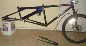
Got a chance to start hacking things apart so I can figure out exactly how to put them together. :)
DSC04077.JPG
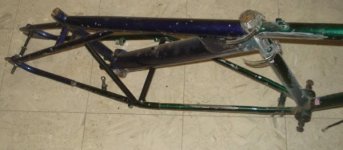
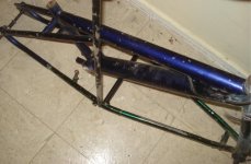
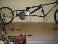
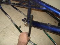
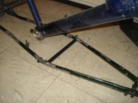
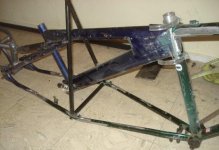
I cut the headtube of the BMX frame in half vertically, removing it's front half. That allows it to mate perfectly against the seattube of the Trek frame, after I cut away and flapdisked the seat stays from the Trek. The pieces removed are below the frame on the floor.

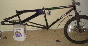
They'll probably be used to complete the bottom of the frame in a fashion like this:
DSC04079.JPG

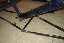
The next thing that needs to be done is to cut the BMX frame's chainstays away from it's BB, and remove the section of chainstay that is not straight tubing from the BB back to the brake studs.

Then use the tubing from the Trek seatstays to extend the straight part of the BMX chainstays to meet the Trek chainstays.
DSC04080.JPG
Something like that. Most probably I will weld a metal plate across the width of that whole bottom section just like CrazyBike2 has under it's battery area, both as a mounting shelf and as stiffener for the bottom of the bike.

If I use the 9C/GM motor as planned, I'll have to leave a space in that plate for it to stick thru, but I am considering using one of the Fusin motors instead, if I can make it work. This would fit just behind the BMX seatpost, in it's modified triangle.

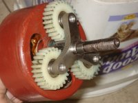
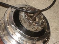
This particular Fusin has no freewheel in it's planetary:
DSC04085.JPG
so I can use it "backwards" with the cover off my 36V fusin that has a few threads for a freewheel:
DSC04084.JPG
Using it backwards allows the freewheel to be used by the motor to pull a chain, and then freewheel when backdriven by the wheel or pedals. I'm just not sure that the few threads this side plate has are enough to let the motor drive it under load. I expect it may shear thru them. :(

I am pondering a way to install a threaded section of BB cup in there instead, perhaps welded to that small threaded area (which is steel), but I am not confident I'll be able to do that in a useful way. Also not sure there'll be enough axle to put a nut/etc on if I do that. There barely is now.

As a side note, the axle shoulder on these is much wider than my 36V, so the bearing is a different type and ID:
View attachment 1
So I have to oil and tap out one of these larger ID bearings from the other cover to put into the threaded-side cover. The smaller one from that cover came out pretty easily, but the larger doesnt'.

I am also looking at my smaller #25 chains and various chainrings to use from the motor instead of bike chain. Just as a comparison, this is a 144T, 80T, and I think a 60T (counted but forgot already), along with a 16T shimano freewheel, in a 26" wheel.

I doubt I'll be using them on the wheel, but rather on a jackshaft, so that I can use the Sachs 3spd IGH in the wheel instead.


I am likely to use the jackshaft Thud made for me to use on CB2 here on this bike, to combine the motor and pedal drivetrains over to the wheel. I'll have to add a BB just for it, probably below the main frame itself. I never did test this out by threading freewheels onto it, as at teh time I didn't have one intact to do so; now I do and find that it's got tight spots here and there that I can't get the freewheel past. So I've been using a BB lockring and a wrench to run back and forth over the threads, using gearbox oil to lubricate them, to cut the threads down to what the freewheel will fit over.

My hands hurt too much to finish it tonight, so the other half will have to wait a few days till I can do more of that kind of twisting. Thankfully it is aluminum, not steel, so it is relatively easy compared to what it could be. :)

Now I have to ponder some more to figure out what to do about some of the other issues I'm coming up against, some listed above and previously, and some yet to be posted.
 
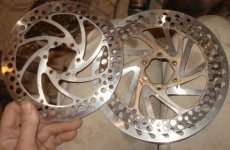
Since I only have a 160mm disc on the front right now, and wanted to go as big as possible, I dug out all the discs and calipers I have, and found the largest is about 180mm or so.
DSC04089.JPG

But after removing the riveted-on thread-adapter, I find it's holes are not ISO standard. :( The Promax 160 on top of it is the original from the Mongoose bike, and the 160 next to them on the left is from AussieJester. Since the original 160 is a tad warped, and rubs in places, I will swap it out for the AJ 160 if I don't resolve the fit of the 180.


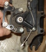
Another issue is moving the caliper outward that extra 10mm. I thought, hey this should be easy; I'll take the adapter from another caliper and chain it to the one I already have. Nope:
DSC04088.JPG
It's so far different that I can't even just drill another hole to use it. Same thing with all the other caliper adapters I have. I really don't wanna make one from scratch, especially since I *also* have to file the holes inward on the disc, and I have enough work to do on the bike to even make it rideable that I don't think I have enough time as it is.

I'm only even taking time to post this because I needed another break from the frustration, so I could ponder some more. :lol: Sometimes typing (or talking) things out gives me ideas.


Another issue I'm having is that I do not have any tubing (round or square) that is long enough (but still light) to make the pieces for the cargo rails/spring supports, which are emulated by the short square tubing in the pics.

I have a 5-foot fencepost, and some really long (8 or 10 foot) 3" tubing, but they're really thick walled and my lathe bed is not long enough to let me shave them down, even if I had time and desire to do that. I also have some square and rectangular tubing on old treadmill frames, but they are VERY heavy, and not very strong, I suspect.

I've also got bedframes, made of VERY heavy angle-iron, but again they're probably not strong in the ways I need them to be, compared to their weight.

Same thing for some rackmount cabinet rails. Either these or the bedframes will likely work fine for the bottom rails, as that's what I did with CrazyBike2 and it worked fine there so far (though I think it contributes to the frame wiggle under power).

I have those short 1" square tubes, and another even shorter 1" square, and a slightly longer but not really long enough 2" square tube, all fo which are strong and light enough to do this, but none long enough.

I also have several old tall 10spd bike frames that have lengths of ~1" round tube I could join together with smaller tube inside, that might work, but I'm not sure since the loading on this part of the bike is not typical, especially with the cargo pods hanging on there. Might still work for the DR, but may cause problems later on.

I don't actually have any smaller tube, though, that will fit right, so I have to use some of the same tube and cut a slit out of it lengthwise, then squish and hammer it into the 1" tube to make it fit. Then weld, just to be sure. Well, I think maybe seatposts might work and be tight enough, but they're heavier.

But I dont' have any other practical way of doing it just now, so bike frame tube it will most likely be.
 
Can't weld 2 bed rails together, to make square tubes ??
 
I hadn't thought of that, but yes. However, then one "tube" will weigh more than all the rest of the frame put together. :lol:
 
Found some round tubing that should work, and is lighter, from a "daybed" futon-couch frame. Camera battery died so no pic yet.
Idea for the bottom frame came up at the same time; am cutting and fitting stuff now to see how it works out. Will likely end up with little or none of the trek's rear triangle in place though. :lol:
 
I think I have the frame figured out; it's just fit together and not welded or anything, in case I or someone else posting here figures out some stupid mistake I've made. :lol:

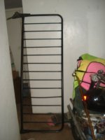
The couch-futon frame mentioned above:
DSC04090.JPG

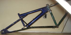
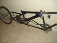
The bike frame currently looks like this:
DSC04094.JPG
The Trek chainstays are spread out, by straightening them at the former bends just at where the tire would've been. This was very difficult, as they're quite strong. :shock: Had to put one foot on the seattube, and the other on the chainstay right at the bend, grab the dropout with both hands, and slowly pull until it was straight. I'm sure it's not great for the metal, but if I have a problem with it I'll replace the whole stay with some other tube. I just don't want to unless I have to.

I couldn't bend them downward, though, to make them line up with the BMX stays. So...I adjusted the BMX stays so that they'd point to where the Trek seatstays I'd removed before would be able to complete their curve (from the seatpost end) right onto the Trek chainstays. It worked more perfectly than I would have hoped for.
DSC04095.JPG

Then the vertical diagonal is black tubing from the couch-futon frame, running from the highest point of the bend up to the juncture of toptube and seattube on the BMX frame. Another piece of that black tubing is fishmouthed and tapped between those elbows of the bottom frame, to triangulate it and help stiffen the whole thing, as well as to prevent it moving inward or outward under loads.
I still would like to make it level between the Trek BB and the BMX bottom of the dropouts, but to do that I would have to cut the Trek chainstays from the Trek BB, at least at the top of them, then reweld them at a different (lower) angle, filling the wedge-gap with other tubing. (or cut the wedge from the bottom side, and reweld the cut edges together, but they may not be long enough if I do that; they barely are now, overlapping the rearward tubes by only 1/2" or so).


The brake studs and probably the accessory hardpoints will be removed from the former seatstays after I am sure how the frame will be done. Then the studs will probably be welded to the front fork's bridge so I can have both rim and disc brakes, which will probably be run to the double-brake handle AussieJester sent me. Then I can engage both brakes simultaneously, adjusted so they both take some of the load, and I should be able to lockup the wheel no matter what kind of load I have on the bike. :)

An alternate for the vertical black tube to the seatpost/toptube juncture would be to run it to the toptube/seatstay juncture instead.
DSC04096.JPG
I'd also like to add something from the same elbow point of the bottom frame to the BB of the BMX, to stiffen to that point, but it may be unnecessary, and indeed in the way of other things.

I'd actually kind of like to remove the entire fat BMX downtube, but I think it is needed for stiffness in the resulting bike. I'm just not sure. I know when I removed the downtube of the rear frame of CrazyBike2, to make more room in the central space, it made the bike significantly less stiff, but it was not shaped or fitted together the same way as this one.


The BB itself (a one-piece-crank type)is not usable directly, but it may work to hold a threaded BB inside it, to run Thud's jackshaft in. A possible setup of this is shown below, but it wouldn't have the jackshaft so far out to the right in reality.
DSC04097.JPG
In this, as in CrazyBIke2's powerchair drivetrain, the pedal chainrings are on the left, as is the motor output. Both feed into the jackshaft via freewheels installed on it. The output of the jackshaft feeds back to the rear wheel's 3spd IGH. Sprockets used were just handy and are not likely to be the actual ones used in the drivetrain.

The motor shown is the 9C/GM hybrid, but the Fusin could be used there just as well.

The chainline should work out withotu any interference to the frame and such, as far as I can tell using these loose chain strips.
DSC04098.JPG


Another shot of the drivetrain area:
DSC04099.JPG


Since I might need to seriously gear up the motor for the race, I needed to make sure that the 144T #25 sprocket will fit in the space if bolted to the side of the 9C/GM:
DSC04100.JPG
It does, just barely. If the jackshaft is placed elsewhere or the BMX downtube/seattube are removed, then it will easily fit and clear everything.

Of course, if I gear it up that much, I'll probably have to pedal a lot just to get started up without blowing stuff up from overcurrent. :lol:

That 144T is pretty big:
DSC04101.JPG
but it will still easily clear the ground, too, even at full droop/bump of the suspension.

Note that the cylinder currently in place of the shock is not permanent, just there to hold the frame at the right angles and such. That cylinder is an adjustable locked-out gas spring, which means that it isn't actually a shock/spring, but rather is a position adjuster, by pressing the release pin at the tip of the extended shaft. On the powerchair this is from, there is a lever like a brake lever that remotely engages this pin, so one may adjust the ride height/angle of the powerchair.

I may well use this cylinder for that function so I can fully lock-out the suspension or limit it's travel under heavy loads, etc. Depends on what I end up with for a suspension, since that still isn't decided. :)
 
The more I stare at the frame along the bottom:
file.php

the more it bothers me that it goes up in the middle. I'm pretty sure I am gonna have to notch the Trek chainstays and angle them downward, so I can fix that, before it drives me nuts.

Also, the more I look at it the less I like having that big downtube in there, but I think I need *something* there, I am just not sure. In my head I can see how the stresses should run, and I don't see any on it, but I know the minute I take it out I'll suddenly see why I wanted it there.


I also test fitted the motor and stuff in the forward center triangle (on the Trek chainstays instead of the BMX), and it'll work there, too. If I do that, then only the drive chain is going to go back thru the rear frame. Right now, the pedal chain goes pretty far back, and the motor chain just behind it. Then the drive chain cuts back thru that area, too, on the right side. But this also means that only the pedal chain (which theoretically won't be used much) runs thru the front triangle.

Whichever section of frame doesnt' hold the motor will hold the batteries, with whatever chain goes thru that frame having to be enclosed so it can't cut thru wiring or cells or whatever, and causing me to have to work around it in battery placement.

The front section is taller, but narrower, and the rear section is shorter but wider. If I take the BMX downtube out, then the front section is even taller and deeper front-to-back, making it ideal for the batteries, and the motor can stay where it is in the pic above, since it so neatly fills that area anyway.


More decisions.... :(
 
Well, it doesn't go up in the middle anymore. :)

I grabbed the angle grinder and cutoff wheel, then remembered that the thing power tools do best is to help me make really bad mistakes really really fast, I decided to use the trusty old hacksaw and file instead:
DSC04127.JPG
I cut a narrow line almost all the way thru the bottom of both Trek chainstays just behind the BB. I left about 1/8" height (about 1/2" of metal) connecting them. Then I bent them open just enough to get the file in there, and gradually opened them up more at the bottom (open end of cut) than the top, so that they would be like a wedge-shaped cut, allowing me to angle the stays downward more.

With the cut open, like shown above, the stays are still "raised", and don't line up with the rear part of the frame yet.
DSC04128.JPG
With the cut closed (to be welded when I'm sure of the results)
DSC04130.JPG
it all lines up:
DSC04131.JPG

Now the frame is pretty darn flat along the bottom, held level here against the floor (raised at the front because of the little bolt-ons for something I forget what it was):
DSC04133.JPG
There's still a little opening in the middle of the cut, but the bottom is pinched closed:
View attachment 5
THe weld will fill that gap, anyway. To make it no gap, I'd have to actually cut off the stays and file them perfect for that wedge shape, and that'd lose me another millimeter or two in length, which I don't want. I need as much overlap between tubing sections as possible.


Remember that short black vertical triangulator I was going to add? Now it's nearly two inches too short, so I've gained a LOT (relatively) of volume just by moving the stays down like this.
DSC04135.JPG

The horizontal bar still fits the same:
DSC04136.JPG
but I'm thinking I'll use one a bit farther back instead, to secure it to the old brake-bridge bar off the former seatstays:
DSC04137.JPG
That gives a bit more to weld to, and more support inside the end of the cross tube, in theory.


This is one possible way I might re-triangulate the whole center section, which brings risers up from the bottom crossbar/stay juncture, up to the BMX toptube/seatstay juncture. They wouldn't stick up like this, I just didn't want to cut the tubing until I'm sure how I will use them.
DSC04138.JPG
Seeing this, I'm thinking more and more that I should remove the BMX downtube and seattube/BB. Just doesnt' seem needed. But I still have this feeling I'll regret it later. :(


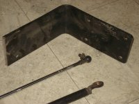
Oh, and that chair back piece I referred to in the DGA thread recently, that I wanted to make the torque arms from? It's this:
DSC04139.JPG
Below it are two hatchback gaslifts from a car, which while aged and not fully operable anymore, still have these useful end joints. On the cylinder end is a simplified Heim joint, which should be useful on my steering tie-rod. There's two of them, one on each gaslift. It's just a brass bushing rather than a bearing, but that should be sufficient for my purposes, at least for now.

The other end is the ball joint on the top lift shown. It screws into something at one end, and the ball is crimped onto the lift's pushrod. Not sure what I will use the ball joint for yet, but it has a bit too much play to want to use it for steering. ;)
 
After asking over in this thread:
http://www.endless-sphere.com/forums/viewtopic.php?f=2&t=26650
for opinions on the BMX downtube issue, I got two replies so far, that dont' discourage me from removing it, but do re-point out the issue of triangulating the center frame, whcih will basically either require making any battery packs I use small enough to fit thru the triangles (not necessarily possible) or making one side's triangulation bar bolt-on instead of welded on.

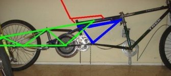
A possible solution similar to what's suggested there:
Triangulation 1.jpg
with the new stuff added in blue (and the BMX downtube removed).


The top blue line is two parallel tubes just below the BMX toptube, attached on either side of the Trek seatpost and the stub on the BMX. Not sure if this will actually accomplish anything.

The two triangulation blue lines are probably what I'll do, though, even if not the top line.

Any other opinions afore I start choppin'?
 
Well, I finally got the chance to cut out the big tube, though nothing else yet.
Side view
file.php


Ortho-ish view:
file.php


Probably gonna do the red triangulations:
file.php


I am so tired (from lack of sleep due to the roofers banging away overhead) I fell asleep several times earlier tonite after getting home from work, to be woken by the dogs for dinner and such. :) I'm gonna go back to sleep soon, once I've sat here long enough to doze again. Afraid to be working with power tools and sharp things in this state, so no more till tomorrow.

A couple of things for scale:
Vpower pack plus 9C/GM:
file.php

The motor will probably actually go with it's axle *under* the frame. Likely the jackshaft for merging the pedals and motor will be under the frame, too, probably just in front of the motor. Possibly it will go above the motor inside the frame.

Just the 9C/GM:
file.php


If I had any, I could fit a metric buttload of LiPo in there. :lol:

Not sure if I'll cut out the wedge or not, as it also reinforces the headtube connection, which will be welded to the seatpost in front of it. I might trim the wedge some, so that it is a wedge in the opposite direction, though, and is less in the way of anything I might put in the open space of that frame.
 
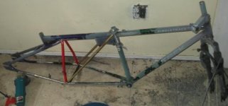
Everything is going slowly, but it is going. Found the right bits of tubing for triangulation, so that I get as much volume as possible inside the frame.

Used some red bits off a kid's walbike chainstays, the rest of which had been used on the old lowracer ReCycle recumbent I never did finish, 2-3 years ago. This lets them be angled a bit at the bottom, so that there is more width in that area by a bit, for batteries and whatnot.
DSC04155.JPG
The forward triangulations will be the gold seatstays off an old PanWorld tenspeed. One of them will have to be bolt-on to get batteries in and out, so it'll likely get hinged at the top end (where I have more space to weld a hinge on) and clamped at the bottom end (though I have not yet conceived how, there are ponderings in the back of my brain).
DSC04156.JPG
Both of the triangulations meet at the bottom where the rack-studs are brazed onto the former Trek seatstays, and I will leave the studs in place so I can screw down a cover to that point later on, or even maybe to do the securing for the bolt-on end of the gold stay. If I don't need them, well, they don't weigh much. :)
DSC04157.JPG

Everything except the gold stays is now cut and fishmouthed up, just have to flapdisk off the paint around weld areas and tack it all together, then continue with the cargo frame/suspension support frame and seat supports, before I fully weld it all together. Just in case. :)
 
Not only am I an incompetent fool, but my equipment doesn't work right either, multiplying my own mistakes and stupidities.

First, apparently last night I lost ALL of my ENTIRE bike toolkit on the way home from work. I didn't even notice until about two hours ago, when I needed something from it, of course, so when I went back to see if it was still there, it wasn't. When making a turn I saw something go flying, and thinking it might be something off the bike I pulled over and walked back to look. But since CB2 won't stay upright without something to lean on or something under the cargo pod, I stuck the toolbag under there to hold it up.

I went to see what it was, and it was just a piece of styrofoam blowing around in the wind. So I walked back to the bike, and apparently just rode off without picking up the toolkit. I had no idea I was that stupid until now. :( :evil: :oops:

I felt horribly sick as soon as I went to go use the kit today and realized what must have happened, but there is nothing to be done about it now, no matter how much I hate myself for being a complete moron. :(

You know what? I would still have my tools if I had only gone back and fixed that damned cracked kickstand with the welder, and put it back on the bike, months ago. But no, I didnt' have time, then when I did I used the time for other things I thought were more important. So much for my ability to prioritize. :roll:


So, now I have none of the right wrenches for anything bike-related, or even to fix stuff on CrazyBike2 or DGA, as I had no spares for most of what was in that kit. Plus they were my favorite tools of other types, too. :cry: My spoke wrench was also in there, so I can't even rebuild that crappy rear wheel I was going to use on the new bike, meaning I have to figure out some other drivetrain for it.
file.php

The only tool I have left was the one that must've fallen out of it into my cargo pod at some point: those little Craftsman adjustable pliers I found a couple of decades ago, which are so worn out that the jaws won't stay in the first position while I squeeze things, and slip to the wider position, making them almost useless for small things I used to use them for all the time. :roll:

Even all my spare nuts, bolts, and good hose clamps were in there, as well as all my driver bits for all sorts of wierd screwheads, including some computer-related ones I have never been able to find again (originally gotten when I worked at CompUSA as a tech).


I feel like crying right now, but it won't help anything. I guess I'll eventually find more tools to replace them, as over the years I found those. I sure can't go buying new ones right now. I have some of the sockets but not all, some of the allen wrenches but not all, and I might have a few of the box wrenches like 5/8", but none of the other bike-specific sizes. Or my favorite combination wrenches that were all american made (and some of them older than I am).

This is stupid--I feel like I killed a friend or something. :(


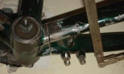
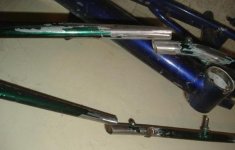
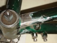
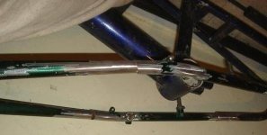
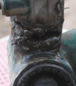
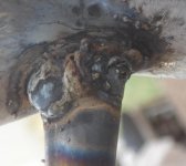
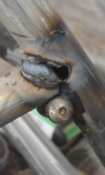
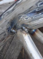
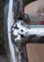
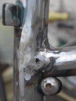
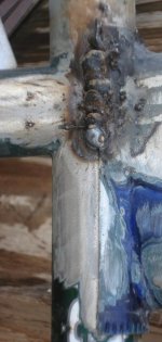
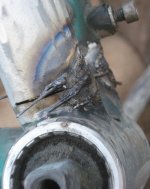
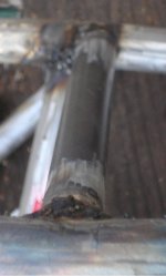
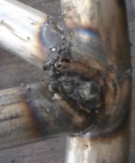
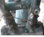
Next, my welder is a piece of crap, and stutters during almost every weld, so I can't even tack weld something without punching/burning holes in thin tubing (which is all of the stuff I needed to tack). My nicely-fitted fishmouths and whatnot were totally pointless wasted time, as the first attempt to do anything on any of them with the welder resulted in destroying the ends by burning holes in them, so I will have to stuff something (welding wire, probably) down in there to fill the area up so I can melt it all into a solid joint later, once I am not so pissed off at myself and the welder.
DSC04158.JPG

SOMETIMES it doesn't stutter. And I can't figure out what the difference in conditions is, as it's not the angle of the handle, cable/hose, etc. Not distance from surface, settings on welder face, temperature, time since I started or finished, etc. It just randomly does it, sometimes as soon as I start, sometimes when I am almost done with a bead, soemtimes in the middle here and there. Just enough to screw up whatever I was trying to do, very thoroughly.
DSC04159.JPG
I've tried a fatter-wire cord from it's internal connections out to the wall, different outlets on different circuit breakers, etc. No change. It just sucks. It's not just the feed mechanism, which will stop for an instant then restart with a sudden push, knocking holes in the hot tubing, but also the arc itself stops and starts, so whatever it is is in it's main power entrance or converter, etc.
DSC04160.JPG
Maybe if I can calm down enough that I don't just throw the thing all the way over the house into the street if I see it again, I can take it apart again and see if there is anything I can beef up or fix inside it that will stop the stuttering.
View attachment 13
So now I'm just gonna sit here for a while, figuring out first what's for dinner, then cook it and eat it, then try to remember what spare tools I might have around here to make a new partial bike toolkit. If I manage to survive all that, I might go deal with the welder. If I fix it, I will probably try to finish the frame.
DSC04162.JPG
If I cant' fix the welder, there's no point in even continuing to do anything at all with this frame, and I'll just have to see what I can do to pack as much battery as I can onto CrazyBike2, to use it in the race instead, and hope it doesnt' fall apart on the track (because it is lately feeling different though I cant' find anything wrong with it's frame).


More crappy weld pics:
DSC04164.JPG

DSC04165.JPG

DSC04166.JPG

View attachment 8

DSC04168.JPG

View attachment 6

DSC04170.JPG

DSC04171.JPG

DSC04172.JPG

DSC04173.JPG


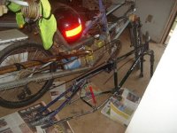
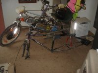
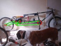
Then some pics of the frame in it's current crappy state next to CrazyBike2:

DSC04174.JPG

DSC04175.JPG
 
Your using a MIG welder right?

If it feels like the wire keeps hitting the surface your welding and pushing the cup away it would be that your feeding too fast, or you are giving it enough power.

If the stuttering is it makes an arc and breaks it, then makes it again etc. etc. Then my best guess would be it's not feeding properly, so either a wire has come loose and the feed motor intermittently gets powered, Or your line is too gunked up with crap (have you run aluminum wire through it at all?). Also whenever your using a wire feed, try to keep the line as straight as possible sharp bends in it keeps the line from feeding properly. Lastly, try the tentioner on the feed wheel inside the welder, it could be it doesn't have enough tension, but be careful not to over-tighten it because you will flatten the wire and just make the problem worse.


If your using a stick welder, then I feel sorry for you, I had to weld a whole bunch of really thin stainless steel with a stick welder and it was a huge pain in the ass. If this is the case, make sure your ground-wire is still intact, and clean up the grounding clamp, next attach it to clean metal relatively close to where your welding (1-4 feet) If you are going with stick, what kind of rod are you using?
 
Xrain said:
Your using a MIG welder right?
Flux core wirefeed, actually. Best POS I could afford at the time, unfortunately at Harbor Freight back when I had a bit of money to spend on one, 2 or 3 years back.

If it feels like the wire keeps hitting the surface your welding and pushing the cup away it would be that your feeding too fast, or you are giving it enough power.
Well, the thing is that when it doesnt' stutter, the feed rate (whichever one I use at the time) is perfect for whatever I am welding at that moment. It's only when it stutters that I have a problem, so that it doesnt' so much push the cup away but instead punches thru the still-melted puddle, leaving me holes in thin stuff or just globbing up on thick stuff.


If the stuttering is it makes an arc and breaks it, then makes it again etc. etc.
Exactly. Doesnt' matter how close I am, either; I even took the outer cylinder off to watch it when it first started happening, and the arc just goes out and comes back, regardless of feed rate or power setting.

Then my best guess would be it's not feeding properly, so either a wire has come loose and the feed motor intermittently gets powered, Or your line is too gunked up with crap (have you run aluminum wire through it at all?).
Never used anything but the flux core that it requires. Back when i was trying to figure out what was happening originally, I cleaned out the feed line with bits of cotton and soap/water, then force-air-dried it, and re-rammed clean cotton thru it to remove any leftovers. Absolutely no difference before and after. :(

Feed mechanism all works perfectly when it doesn't stutter, and when I am not trying to weld. (if I just hold it out and feed, even when holding the end against something to push back on the wire).

Also whenever your using a wire feed, try to keep the line as straight as possible sharp bends in it keeps the line from feeding properly. Lastly, try the tentioner on the feed wheel inside the welder, it could be it doesn't have enough tension, but be careful not to over-tighten it because you will flatten the wire and just make the problem worse.
I generally put the welder behind me, as far away from the welded object as the cable goes, to keep the line as straight as possible, but it also doesnt' make any difference.

If your using a stick welder, then I feel sorry for you, I had to weld a whole bunch of really thin stainless steel with a stick welder and it was a huge pain in the ass. If this is the case, make sure your ground-wire is still intact, and clean up the grounding clamp, next attach it to clean metal relatively close to where your welding (1-4 feet) If you are going with stick, what kind of rod are you using?
I could probably weld this easier with a stick, if it had a good range of current adjustment. :lol: At least it would have a continuous arc, and not stutter.

I have even undone the ground wire from the clamp, and BOLTED it to the workpiece on a freshly-flapdisked surface, to no avail.


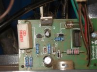
I'm pretty sure the problem with the welder is in getting power to it, somehow. Internally, someplace between the input from the AC cord and the point at which power is split off for the feeder and the arc, it's not working right. That's what I have to determine by opening it up again to find out.

I already eliminated the ac outlets and breakers and whatnot by trying all the ones capable of running this thing. Also, some time back, by having an LED lightbulb plugged into the same duplex outlet as the welder, and watching for it to flicker during the stuttering (this is a difficult thing to set up if trying to do it with your own eyes, had to use the camera to record it, with the door shut between the welder and the room the outlet is in with teh camera and bulb). The LED bulb I used flickers or goes out whenever anything in the house makes even a tiny "brownout", like when the refrigerators come on, etc. I can't see the flicker on a regular bulb, but can with this one. No flicker, so that means it shouldn't be being caused by the AC supply to the welder itself.


I'm about ready to build a welder out of a motor controller running a small motor that drives a really heavily-wound motor (like the one out of a treadmill, perhaps, or a car alternator) as a generator, rectifying that, and running it to the electrodes. Then hook that into the HF feed mechanism that seems to work ok. THen I could use the motor controller to vary the current by varying the motor/generator speed, in theory. Better than having just a Hi and Lo setting like the HF welder has.
 
amberwolf said:
I'm about ready to build a welder out of a motor controller running a small motor that drives a really heavily-wound motor (like the one out of a treadmill, perhaps, or a car alternator) as a generator, rectifying that, and running it to the electrodes. Then hook that into the HF feed mechanism that seems to work ok. THen I could use the motor controller to vary the current by varying the motor/generator speed, in theory. Better than having just a Hi and Lo setting like the HF welder has.

that is hilarious...if your not joking you should document that build :)

In any case your a mad genius...dont lose hope...i for one am rooting for some ride videos.
 
For videos, I'll get them on CrazyBIke2 if I have to, but I REALLY would like to finish this bike and then use it to race with.

For the welder idea, well, in theory it should work, but in reality I'd probably just melt everything into a puddle at the wrong end of the welder. :lol:

I know there are welders that work this way, as I learned on a stick welder like that back in highschool shop class, 25 years ago or so. When you turned it on, there was a motor whine that increased in pitch very fast until it spun up to speed, then would vary whenever you struck an arc. If you dialled the current differently, it would also change pitch.

At the time I had no idea how it worked, but once I started messing with the ebike motors, generators, etc., a few years ago, it struck me that that must be what it is doing inside. Later on, when I was looking into welders to build my frames with, I found that is exactly what they do; some use a gas or diesel powered motor and some use electric, that drives a generator that provides the welding current. There's even threads like this one:
http://www.practicalmachinist.com/vb/fabrication-cnc-laser-waterjet-plasma-welding-fab/motor-generator-welder-troubleshooting-204197/
that describe how to revitalize one should it not be working.

However, I don't have time to figure out how to build one now, much less troubleshoot THAT, too, so it will have to wait for another time. If I do indeed build one, I will certainly have a thread for it. :)


As for losing hope, well, I took a good look at the welder, and despite verifying contacts (and even recrimping and then soldering several high-current connections), it still just stutters much of the time. Too much to weld this frame with, cuz I just keep burning holes.

The only thing I haven't done, which I will once I get done feeding the dogs in a bit, is to bypass both the power switch and the thermal cutoff on the transformer, in case one of those has an internal problem causing high-resistance or something. Since it does it for both positions of the Hi/Lo rocker switch, I don't think that one is a problem, or it would likely only happen in Lo, as I have only used the Hi a very few times. If it comes down to it I'll bypass that one, too, in "permanent" Lo mode.

Well, I also haven't verified power levels and such to the feed speed control board, but I don't think that's the problem, since it operates fine as long as I'm not striking an arc. If I just feed, it works great.

One thing I can do to eliminate feed as a possible issue is to make a temporary stick clamp instead of the feed tip, then try welding with some steel rod (I don't have any actual welding sticks) on scrap metal. If it won't keep an arc there, either, it's not the feed. That will probably have to wait till tomorrow, since it's dark outside where all my bits and bobs are to do that with, and flashlights aren't enough to see thru the mess to find things. :)

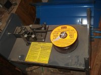
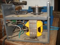
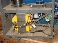
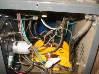
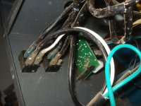
Pics of the welder's guts, including where I crimped and soldered on the ground clamp's wire:
DSC04176.JPG

DSC04177.JPG

DSC04178.JPG

DSC04179.JPG

DSC04181.JPG

DSC04182.JPG

DSC04183.JPG

 
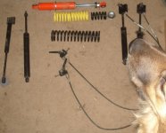
Woke up and couldn't get back to sleep, so dug around for more parts, and re-found the shocks and springs I'd been looking for.

Some ideas I might try:
DSC04187.JPG
The yellow springs are not that strong, about the same as the long black spring that came with the orange shock, but since they are shorter they will allow me to also put the 750lbs/in spring off the MTB shock on there, along the shaft of the shock. The yellow springs might give a bit more pressure, then the short black 750 spring would compress between the head of the shock cylinder and the pivot end.

I don't know how well it might work, but first I have to locate my vise grips, since I no longer have wrenches that fit the nuts on the end of the shock to get the pivot off of it to get the spring and washers on there. :(

The orange shock with springs would then go onto the MTB shock mount on the rear swingframe, directly in line with the toptube of the bike, so that it pushes along the toptube, preventing any failure of triangles like happened with Crazybike2's experiments using the same shock before. :roll:


Also shown in the pic are those lockout-able gas springs I was talking about before, along with their lockout actuator cable/lever assemblies. On the almost far left is one without the assembly. ON the very far left is a gas spring that used to help unfold a treadmill, cut off of it with it's pivots intact to be welded to something else later. The latter might be useful for more damping if I have to, but the lockout-able ones would be better, as I can fully lockout the suspension with them if necessary.


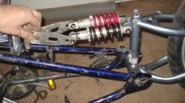
This idea uses just the MTB shocks/springs, a pair of 850lbs/in:
DSC04189.JPG
I'd need to build up the swingframe's mount points so it embraces all of both sides of each shock's pivot, and the same for the other end that goes onto the bike frame. I'm just holding it there as an example, with some metal plates I had in the box with the shocks and stuff.

I expect that I'll need the two heavy-duty springs to be able to handle the cargo loads, but I won't know til I try it with the lesser ones. I think I had a PDF around here on how to calculate this stuff out, but since I don't know what the springs are except for those two 850s and the 750, I can't know what the actual results will be until it's tried.


The other thing I think I'm gonna do is ditch the heavy crappy Mongoose fork, even though it's the only one with disc mounts, and use the one that came on the Trek when I got it--the Manitou Skareb. It still needs service, but even with that it has to be better than the Mongoose.

It does have a place to screw on a disc mount, but I will have to make an adapter to go there and hold calipers. The hose hanging off teh top left of it is just an extension to let me air it up easoer with a regular bike pump.

Mostly I'm considering all these changes since without a reliable welder, I doubt I can finish it before the race anyway, so I might as well ponder all the things that'll make it nicer for a cargo bike on the roads around here. If I get teh welder fixed then maybe I can implement them for the race itself.

Now I'm tired enough to maybe doze off again....
 
Three ideas, what I would do if I had to:

1) braze it instead. Incorporate laps etc to allow brazing

2) use battery from bike to weld with stick.

3) build bike from thicker steel to allow stickwelding more easily

And dude, getting all the fishmouths right, then having the welder wreck them? That is the WORST!!

Katou
 
katou said:
1) braze it instead. Incorporate laps etc to allow brazing
If I had a torch for that, I would actually have done that to start with on all the space-frame area, cuz it's much neater and easier with thin tubing, and also the Trek frame was actually brazed together to start with, every place I've ground away the paint at a tube-tube connection so far.

2) use battery from bike to weld with stick.
I have car batteries I can do that part with, and a still-pondering-plan to use those in place of the transformer/AC power in the welder, still using the rest of the welder so I can still wire-feed it.

3) build bike from thicker steel to allow stickwelding more easily
Yeah, that's not an option unforutnately, as I don't have small-enough diameter tubes in thick steel that isn't really soft heavy crap. Plus, the places it's burning thru are mostly the really good (but thin) steel of the Trek frame, which I specifically wanted to use for those qualities. :( Some of it is thicker, like the three large tubes of the front frame, but the stays are not, and that's where I have to weld, of course. :roll:

Otherwise, yeah, I would do that.

And dude, getting all the fishmouths right, then having the welder wreck them? That is the WORST!!
Yes, it is. :( I wasted about three or four hours doing them nice and slow, so I could fit them perfect and not have to fill gaps. :evil:


Not a lot done yet, still sorting thru boxes looking for alternate tools to do stuff with, to replace the lost ones. Found a few, but not enough yet (some I'm gonna have to find time go to a pawn shop and dig thru their cheapie bins to replace).

I found the vise grips to get the shock apart, so I put the springs on there, and it does appear to work as expected, but the yellow springs are so weak that they compress completely before I've even put all my weight on the frame. So they're useless, and I'll end up taking them off. They're what's making the rear end so high in the pic, cuz the swingframe ought to be about level at the bottom with no weight on there.

THe black 750lbs/in spring does appear to do the job, though. Might need the 850 instead, we'll see.

I don't know if it will do any good, but i might be able to fit the original large black spring over the 750 or 850, and since they coil in opposite directions they shouldn't get tangled during compression. Then I get soft spring from the large one and full hard spring from the small. Would have to test with and without the large spring, once the rest of the bike is at least pedalable.

The shock is not mounted to anything at the front end yet, as I have to weld on some braces for that, and that will wait till I decide what spring to use, so I can figure where it needs to start at for the correct starting ride height, to allow the chainlines to work out.

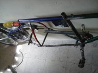
DSC04193.JPG
Looking at the chainlines, I was thinking that rather than the jackshaft in the middle, between motor and pedals, I would be much better off putting it down just below the swingframe pivot.

Possibly putting a guide sprocket over the pivot axle itself, so that the top (power) side of the chain is never slapping the pivot or frame. Dunno if it's needed yet, as I am still working out chainlines.
View attachment 2

AUGH! I just realized when drawing up the above that with the pivoting swingframe and whatnot, I HAVE to use a derailer on the back so I can get the slack in the chain needed for the pivot to move, unless I put a second jackshaft (dual sprocket) on the pivot itself. :( I didn't want to do that cuz it doesnt' help the whole high-powered stuff work well, can't seem to get as good a tension that way.

Great. One more complication I shoudl have foreseen. :roll: I'm doing good on the stupids this week. :oops: I guess that means it'll actually end up like this:
Copy (2) of DSC04192.JPG


This is the part I really hate: working out chainlines and sprocket sizes for gear ratios. I generally screw them both up quite a bit before making them workable. :roll:
 
There must be custom bike builders in your area. If you could get them interested in what you are trying to do, they would probably accede to doing a weld or two for you, heck, any fabricator would do.

Given you dedication, and the crazy-ass setups you ride, I feel pretty confident that you could get some buy-in not too far from the homestead.

I mean, if I was local to you, I'd totally help out, just for the kick of seeing you out there.

Idea?

Katou
 
Back
Top