Cromotor + MethTek Monster 24FET + 20S lipo build

Lebowski said:
here some info on the new Swiss e-bike laws:

http://www.astra.admin.ch/dokumentation/00109/00113/00491/index.html?lang=de&msg-id=43608

Basically it'll be allowed (from may 1st) to have 500W, you can go upto 20kmh under motor
power alone, upto 25 with pedalling and it'll still be a normal bike for which you need no prufung :D

Looks good. For another build I will try to limit my powers to 500 W....
For my current 2WD, it is a nice challenge to get my bike registered as MoFa with 1.0kW and 30km/h.
 
OK, after some days riding my 2WD it is time to look back and do a first evaluation.

For completeness sake, first my bike usage. I usually bring the kids to school with the trailer, then return the trailer home and drive to work. After a day's work I get home, recharge my lipo's and are ready for the next day. I have no experience yet with trail riding. That will come when the weather is better.

The kids (1 or 2, depending on the weather and other circumstances that makes the older one unable to go to school herself) go to school 1.4 km away. That is 1 km flat, and the last 400 meter uphill on a 10% slope. I usually do not drive faster than 40km/h with the kids, and I take that 10% hill with 40km/h without even going WOT. Total weight is probably 180 kg (me 70kg, 2 kids a 15kg = 30kg, bike + lipos 30 kg, trailer 20kg), so that is not too shabby. Back from school, going down with the empty trailer, I need my brakes a lot. And here is where I am not happy with the huge weight of the 2WD and the crappy mechanical disc brake caliper on front. Once on the flat area, I do 45 km/h going home returning the trailer.

Anyway, I continue going to work without the trailer, doing 50-55km/h where possible, stopping for all 6-7 traffic lights, accelerating hard from standstill to WOT (55 km/h). Going back is the same. The commute is 4.5km with 2 steep but relatively short 10% hills on the way back. I take these hills at 45km/h. Again, not too shabby.

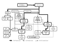
Now, I have the CA connected to my rear motor. During acceleration, current peaks to 55Amp. Mind you, that is rear only. When connected to the front, the CA measures peaks of 20-30 Amps when accelerating up to 30km/h. After that I guess the rear HT3525 takes the full responsibility and the front 9C 2810 is being taken on a tour (0 Amp).

When I come home, I have traveled 14km and spent 400Wh. That is 28Wh/km, or 45Wh/mile. My 10kg 20S3P 13.5Ah pack gives me about 1kWh. So my total range (disregarding LVC) is about 35km or 21 miles. That sucks, and leaves me with very little actual range, which is closer to 25km before I hit LVC at 3.6V/cell.

So to increase range, I can do the following:
  • Get rid of the front motor. This gives probably the largest effect, at the cost of hill climbing power. I do not want to do this yet, but I may consider it.
  • Drive slower. This takes away most of the fun. Again, I do not want to do this yet, but I may consider it.
  • Increase my battery pack. This is one area where I see a bigger improvement. I have been reading this thread on super quality batteries, and I may switch from Lipo to Panasonic NCR18650A cells. However, I will need a lot of them in parallel in order to get my desired current and not exceed the C-rating. Taking a maximum of 80Amps, a cell of 3.1Ah will give 3.1Amp at 1C, meaning I need 25cells in parallel (25*3.1=77.5Ah). And at 20S25P, I get to 500 cells. At a weight of 50gram/cell (including tabs), that would be 25kg. Too much. Of course, I would then have a 77.5Ah x 80V = >6kWh pack. If I can get to discharge at 2C, it would obviously cut such a pack in half. And with a pack of 3kWh, my range would still be three times my current range, at 12.5kg. Any bright ideas?

So, I read with interest Lyen's post about these batteries. His pack was 7S24P and almost 2kWh at 7.7kg. Hmm.
 
Lebowski said:
How about using regen on the downhill parts ? This also puts less stress on your brakes...

Yeah, working on that. I need to replace a resistor with another, and I have not had the time to figure out which resistor I need. However, regen would help me with only another 10%. Remember, every hill I go DOWNwards, I need to get up again eventually. For my commute it is really no issue. For my summer trail rides, I guess I just have to bring another lipo pack...
 
Small update. I rode 18km yesterday and today, and I ended up with 74V on the CA with the occasional sag at accelerating to 72V (LVC). Total of 500Wh, aka 27.6Wh/km.

It is quite cold over here, about +5* Celsius, which may have a large negative impact on the Zippy 10S lipo packs, because when I measured voltage at room temp, all cells were at about 3.85V. Coming days I will bring my voltage meters with me to check while on the road.

I also looked into some nice trails around here. When it is warmer, I will try this trail: http://trails.mtbr.com/cat/trails-around-the-world/europe-trails/trails-europe-other/trail/gempen-schartenflue/prd_369056_4538crx.aspx
 
Another quick update.

Actions
This weekend I removed the front 9C and replaced it with a normal wheel. I removed the second controller, and reduced the lipo pack from 20S3P 13.5 Ah (1kWh) to 30S 1P 4.5Ah (still 500Wh).

Results
Weight reduction is very significant. Handling of the bike is very much improved. 10% Hill climbing results in hot motor at 50km/h for a couple of minutes at half throttle. Energy-wise, over my 11km commute, I spent almost 250Wh, aka 22Wh/km. Not much of a reduction, however, my range to LVC is now actually the same with a huge reduction in weight and very much improved handling.

Conclusions
I tried 2WD. It is great for super hill climbing. However, for commuting, I will probably stick to RWD.
 
This morning the CA reported 23Wh/km (RWD with rear HT3525, 30S1P 4.5Ah, Lyen 121445 controller 45A). I was accelerating very hard and going 60km/h to keep up with traffic. At these speeds, I really have to hold onto the steering bar. I will also have to rethink tires and read up on it on ES, because I am a bit nervous about getting a flat at >50km/h.

Anyway, I still have to saw the steel plate and put the lipos in a protective case. I also received the epoxy from Wojtek to attach Doc's TAs to the frame. So, there is enough for me to do with my bike. The main limitations of course are that I need to keep commuting on this bike, and that I need to balance working on my bike with spending time with the wife and kids. So, time is the most precious thing at this moment.... :p

I may prepare my bike for easy converting to 2WD when I start hauling things around or plan for heavy hill climbing stuff. However, for commuting 2WD is not the right thing for me.
 
Lebowski said:
if your wife would have known all this when she gave you the cheap chinese ebike.... :D

My wife is more intelligent than I am, and is fully aware of the forum. I probably have to be grateful that she is not too interested in this stuff.... :mrgreen: Oh, and she appreciates the fun that I have with this big boy's toy.
 
Update.

Today I did quite some nice stuff with my bike.
  1. opened the controller, and added a dab of solder to the shunt like this.
  2. recalibrated the CA according to the procedure described here using my iCharger in foam cut mode, both at 10.0A and 9.0A over the Ground-Phase, and had to change the shunt resistance to 1.645 mOhm (from 2.000 mOhm). So, not too extreme.
  3. installed the USB software to program the controller
  4. changed rated current to 58A, phase current to 145A, regen voltage to 60V, regen power to 2, speed 1 to 40%, speed 2 to 60%, speed 3 to 120%, and block time to 3.0 seconds.

Results are amazing. I will do some more current measurements later on a nice steep hill (something between 10 and 20% incline), but the CA sees more than 60A during the first 3 seconds, and in the high 50s after that initial burst. With 126V fresh from the charger, that gives me temporary bursts of 7.5kW. After a 500m >10% hill, the motor feels handwarm, and so does the controller.

Next steps are installing the temp probes on the motor and controller, with readout on the steering bar. I can't wait until V3 of the CA comes out, integrating all these sensors....
 
I get almost 9% regen when using this strong regen settings, biking on hills and e-braking for traffic lights and intersections. The loadfree topspeed at WOT 120% is more than 100km/h, and the wheel keeps oscillating around 100km/h, probably due to the CA speed restriction of 99km/h. Of course, it is not really relevant for normal driving, but closing in on 80km/h will be nice...

Hill climbing is awesome, and makes me remember my 2WD config. However, I am very conscious of the possibility of frying my HT3525 whereas I did not have that fear when running the 2810 in the front as well. We will see....
 
My first movie here is an unedited movie of this morning's commute. A bit boring. Fast though.

[youtube]oYq-clp4Jwg[/youtube]

Some details:
Starting voltage HOC 30S 2P Lipo = 125.9 V with Vmin at 113 V (10% voltage sag during heavy acceleration). This short commute involves skirting around the city and is 6.016 km long (3.74 miles). End voltage at rest = 121.1 V. Total Watt-hrs = 191.97 Wh with 29.7 Wh/km (47.8 Wh/mile).

The fast part is at 05:10 in the vid. Most of the time velocity is at 40-45 km/h, which is the speed limit in Switzerland for E-bikes. Regen was 8.1% with Amin -10.7 A (1.3kW). Amax = 80.45 A with Smax = 82.3 km/h (51.1 mph) (not in Switzerland).

Clyte motor axle is caught in 3 torque arms; one on the right side (derailleur), two on the left side (disc brake).

Apologies for the change in camera PoV and the awful sound.
 
I just ordered a HALO SAS rim with some 12ga black Sepim spokes from Holmes Hobbies in order to lace my HT3525 in a rim/spoke combination that will sustain some nice jumps. Not that I can jump well, but if something goes wrong it better not be because of the wheel.

See MadRhino's great write-up here on lacing a big hub motor into a nice rim with flange washers and rim washers. I used the Grin spoke calculator to determine the correct length for my spokes, and (on advice of MadRhino) added 2mm more to allow for the washers.

rmha-sas-26-cp.jpg


logo.gif


file.php
 
The spokes came in today (I ordered them on the 12th of April, i.e., very very fast delivery - 5 days - from the US to Switzerland, kudos to John Holmes and co.). I did some rude measurements:

  • Spoke length: 167 mm (as ordered).
  • Spoke width: slightly over 2 mm (12AWG ordered). Converting 12 AWG to mm would result in 2.05 mm.
  • Maximum spoke head width: 5mm.
  • Maximum nipple width: 5mm.
  • Maximum nipple head width: 8mm.

This means that
  • for the flange washers / rivets I should look for inner diameter of 2.1-2.5mm and outer diameter 3.0 mm (size of the flange hole).
  • And for the rim washers, inner diameter of 5.2-5.5 mm to allow for the largest support.
  • It would be even better to have spherical washers for the rim, and I found these steel spherical washers with an inner diameter of 6.4mm and an outer diameter of 12mm.
    AMF-186_Photo2.jpg
  • Given that the head of the nipple is already kind of spherical, I gather I only need the bottom of these spherical washers, like these: http://www.reidsupply.com/sku/AMF-193/

I need to get the rim in, in order to see how large the nipple holes are. I may even add another larger washer under this spherical bottom washer (if the length of the spokes allow) to spread the forces even more over the rim. This was recently reported by GCinDC when looking at the lacing of dbaker:
file.php
 

Attachments

  • IMAG0588.jpg
    IMAG0588.jpg
    66.8 KB · Views: 2,170
  • IMAG0589.jpg
    IMAG0589.jpg
    76.3 KB · Views: 2,170
  • IMAG0590.jpg
    IMAG0590.jpg
    79 KB · Views: 2,170
  • IMAG0591.jpg
    IMAG0591.jpg
    69.6 KB · Views: 2,170
  • IMAG0592.jpg
    IMAG0592.jpg
    75.4 KB · Views: 2,170
  • IMAG0593.jpg
    IMAG0593.jpg
    80.5 KB · Views: 2,170
  • IMAG0594.jpg
    IMAG0594.jpg
    91.6 KB · Views: 2,170
I am waiting for too much stuff to come in. Therefore, this weekend I played around with some footage and a NLE. This is first result of my editing efforts, so don't go tough on me. Halfway you can see a crow being hit. I could not avoid it, but looking back he (or she) survived the impact :mrgreen: . Obviously this was not recorded on my GoPro that was fixed to the steering bar.


[youtube]iQTTvHQYTKI[/youtube]
 
My HALO SAS rim has come in. Now I just need a quiet weekend to start lacing. That quiet weekend is hard to find, and we are moving houses as well. So it may take a while.

In the meantime I changed to a current throttle. Thanks to Grin for selling me their great CA and documenting it well, and thanks to Methods for well describing the tuning of the throttle.

Theory:
There are multiple factors in play that determine the reaction of the motor to a change in throttle input when using current-throttle via the CA.
  • Actual turning of the throttle by the driver
  • Throttle output at a given rotation, typically measured at bottom and top
  • Output of the CA at a given throttle input
  • Output of the controller at a given input from the CA
Therefore, we need to know the throttle output, and range for when the controller reacts, and then set the CA to match these to our liking.

Methods:
  • With the throttle connected directly to the controller, I listened to the motor at what throttle voltage it would start to turn (1.56V), with the voltmeter on the black and white wires.
  • Methods also describes that you should be able to hear the controller switching from PWM to constant output. I did not know what to listen for, so I left this step out.
  • Opened up the CA
  • Entered 2x 3-wire throttle wires into the case - one with a connector to the controller, the other with a connector to the throttle
  • Soldered the red 5V ends of both wires to each other
  • Soldered the black grounds of both wires to the ground pad on the CA
  • Soldered the white throttle signal from the throttle to the Vi pad on the CA
  • Soldered the white throttle signal towards the controller to the Th pad on the CA
  • Added ground / 5V source to black and red throttle wires
  • Measured throttle output (0.826V – 3.7V) with the voltmeter on the ground and signal wires. Bottom output would vary a bit between 0.820 and 0.840V.
  • Set (CA-manual section 8.17) Aux Voltage Function to current.
  • Set (6.5) max amp to 60A
  • (Almost) eliminated slop at the bottom of the throttle by setting 8.18 AUX threshold to 0.85V to allow for the variability in throttle bottom output. In other words, setting the AUX threshold to 0.84V would sometimes have the motor start running as soon as I left the settings-panel in the CA, without giving throttle. I tried different settings, but setting the AUX threshold at 0.85V would give me the best balance between ensured no-running motor at no-throttle and almost elimination of bottom slop prior to start of the motor.
  • Set 8.12 iTermMin to 1.55V and 8.11 iTermMax to 3.3V. I did not change any of the feedback gains because I am happy with how the motor reacts to the throttle input.
Results:
  • Almost no slop in the bottom of the throttle.
  • Almost no slop in the high end of throttle input.
  • much better control over acceleration. Low throttle input means low acceleration, whereas high throttle input means a LOT of acceleration (up to 80A peaks without limiting)
  • Still needs careful management of throttle when starting from standstill.
  • Maximum Amps according to the CA are indeed below 60A. No more 80A peaks anymore
Conclusions:
In the V2 “Large Screen” version of CA, current-throttle works like a charm. I am currently attaching another throttle to my beta V3 CA, and adding some more connectors to make it an easy plugin into my bike. We will see how the V3 makes the throttle even better manageable.
 
Had a rear flat yesterday. Huge thorn punctured my Nobby Nic and the Continental MTB tube within. I hate flats, especially on the rear.

This was as good a time as any to change tires to something my commute will appreciate. Schwalbe Energizer rated for 50km/h, especially for E-bikes. We will see...

Photo%2005-05-12%2018%2009%2038.jpg


Photo%2005-05-12%2018%2010%2025.jpg


Photo%2005-05-12%2018%2013%2048.jpg


Photo%2005-05-12%2018%2013%2056.jpg


Also decided to clean up my steering bar. This is the result:

Photo%2005-05-12%2018%2011%2052.jpg


Photo%2005-05-12%2018%2011%2038.jpg
 
Well, I am chickening and postponing the check. My main justification is that I want to do some more testing (aka adding temp sensors) before I "finalize" the build and (hopefully) get it approved. In the meantime I am riding low profile, keeping below 45km/h and pedalling...

I am having fantasies of covering the bike (and all electronics) with nice curvy carbon fiber... inspiration from this:
[youtube]oXL5VCOjBO8[/youtube]

Project link.
 
OK, so I will be moving to a more hilly area approximately 15km/11miles from work, and my commute will change significantly.

Therefore, the criteria for my commuter e-bike have changed:
  1. Able to easily negate the hills (most of them around 10%, some of them up to 20%) at approximately 30km/h while at the same time keep top speed on the flat high (around 75km/h), without overheating.
  2. Preferably able to do one day's commute (30km) on one charge. If going beyond that, I will charge at work.
  3. Removable battery in the triangle to allow for easy charging at home and/or at work with weight in the right place.
  4. Optimized for tarmac roads, while maintaining the occasional "good wheather" off-road venture on very easy non-technical trails (no jumps).
  5. All electrical components hidden behind a removable body that covers frame, components, and all wires, to discourage occasional vandalism / cops.
  6. Make the bike ready for cop inspection, with controller programmed for maximally 74V 12A (1kW) and all electronics documented with specifications. Planned for inspection in August 2012 (ouch, I set myself a deadline....).

Now, this is the solution / new project plan.
  1. In order to be able to easily negate the hills (most of them around 10%, some of them up to 20%) at approximately 30km/h while at the same time keep top speed on the flat high (around 75km/h), without overheating, I plan to go back to 2WD with my 9C 2810 in front, and with my HT3525 in the rear, both connected to a Lyen controller, with my current CA v2 in front, and my beta CA v3 in the rear, at 126V. The overheating risk will be mitigated by including thermistors in both motors and both controllers, and of course by the 2WD setup. I will arrange for the rear HT to take most of the work (60%), so the thermistor in that motor will be connected to the CA v3 and included in the limiting features. I recently added a thermistor to my 9C, and it was a real PITA. Hopefully it will go easier with my HT. I am also still experimenting with oil cooling, so depending on the results I will oil cool both motors as well. Both controller thermistors will be connected to the CAnalogger, but by doing 2WD I really hope to avoid any controller heating issues, so this is for scientific purposes only. I plan to use the 30S 2P 9Ah pack, so topspeed should be good on the flat, altough I may have to tweak the front Lyen controller to 120%.
  2. Preferably able to do one day's commute (30km) on one charge. If going beyond that, I will charge at work. Assuming an average energy consumption of 30Wh/km, doing 30km would require 900Wh. With my 126V 9Ah pack, I should be ok without a lot of energy to spare, though.
  3. Removable battery in the triangle to allow for easy charging at home and/or at work with weight in the right place. Now this is a nice challenge for which I am going to learn how to create glass fiber boxes. I don't want to create a frame from CF or glass fiber. But I think it is perfectly possible to create a galss fiber battery box and place that inside the triangle. Then add some glass fiber covers to cover all electric parts and the battery box, with a nice entry to the battery. I am thinking about very simple light thin sheets of wood to get the forms right, and then cover that with fiber glass / epoxy resin to add strength.
  4. Optimized for tarmac roads, while maintaining the occasional "good wheather" off-road venture on very easy non-technical trails (no jumps). This allows for my Schwalbe Energizer tires. They are very silent, very fast, and give very good grip even in the rain. Very happy with them. Of course, off-road will be a bit slippery....
  5. All electrical components hidden behind a removable body that covers frame, components, and all wires, to discourage occasional vandalism / cops. See above, the fiber glass thing. I hope to integrate both CAs as well in a nice way.
  6. Make the bike ready for cop inspection. Laws locally say 1.0kW is the max, with 30km/h max without pedaling and 45km/h wiht pedalling. With the bike programmed for maximally 74V 12.5A (1kW) with a max speed of 30km/h, and all electronics documented with specifications. If I can get all the above right, then this will be a simple reprogramming of maximum battery current and maximum speed at WOT. Increasing block time to 2 or 3 seconds should give me enough oumph to accelerate, while still being able to maintain the limitations of 1kW continuous power. I have made a schema in powerpoint (by lack of experience with a better electronics software program) that shows the main connections between the different electric components. For the inspection, the front 9C will have a max of 400W (74V 5.5A), whereas the rear HT will have a max of 600W (74V 8A). I was nicely provided with stickers that show these specs as well.

Suggestions / comments are more than welcome!!

Oh, and the 74V battery and 20A fuse are for when I go to the inspection. And before you ask, the stepdown from 74V to 19V with a laptop converter and then to 5V and 12V was necessary because my 100V-12V converter does not provide enough power (1A max). The laptop converter gives me 19V 4.2A (80W), which is then divided to a 5V 1A and a 12V 3A current.
 

Attachments

  • bike.jpg
    bike.jpg
    25.4 KB · Views: 2,326
OK, so I destroyed my HT3525 when moving up a 15% hill at 50km/h (126V 55A). I knew it would break eventually, but it broke after 10 minutes going uphill, instead of after 2 minutes as indicated by the simulator (ebikes.ca). Now, I actually did NOT want to break the motor, but I could not help myself enjoying going uphill at that speed. It is just too much fun.

I will open the motor and try to diagnose what is wrong. Either halls are dead (most likely, because the motor reacted initially by behaving like when one of the hall wires is not connected well), or there is another short. We will see.

I tried to attach my 9C 2810 in front to get at least some motorized bike ready to go to work. I got it to work electronically, but when I inserted the motor into my other Fox front fork and tightened one of the bolts, I broke the dropouts. Again!! So, now I have proven that the Fox front forks (TALAS 32 and F100) have dropouts made of butter. Even with torque arms, they are NOT good for front motors.

I will try and learn how to weld. Then I will attach Docs super torque arms onto the fox front forks and we will see if that is better.

In the meantime I went to work pedalling. It is a commute of 16km, and it took me an hour. Not that bad, considering all the hills in between. Maybe I should do that more often... muscle-power rules now!! :evil:
 
dnmun said:
you broke the alloy fork even though you had the C washers inside the lawyer lips?

I broke the dropouts as follows
Big washer inside both dropout
C washers inside lawyer lips outside of dropout
torque arms around the axle against C washers (torque arms not yet fixated to the fork)
Fancy locking washer
Bolt

Bolt was the wrong bolt, with the wrong thread. I applied power with a wrench trying to put the bolt on. Instead of the bolt turning onto the axle, the whole axle turned inside the dropouts. Dropouts dead. :(
 
hjns said:
OK, so I destroyed my HT3525 when moving up a 15% hill at 50km/h (126V 55A).
I tried to attach my 9C 2810 in front but when I inserted the motor into my other Fox front fork and tightened one of the bolts, I broke the dropouts. :evil:

Anyway, your build is amazing !
 
jpgey said:
Anyway, your build is amazing !
Thanks!

I have not had the time yet to open up my HT. In the meantime, I drive around on my front 9C 2810 at 126V 45A max (controller programmed). I do baby this hubbie, because I definitely do NOT want to destroy my last remaining motor. So average power going into it is around 1.3kW (10A). This still gives me a cruise speed of 50kmh (32mph). Topspeed at WOT is 60kmh (37mph). With the hills on my commute, I temporarily allow myself 20A (2.5kW), but according to the sim anything above 2.5kW will be converted right into heat. CA programmed to 25A max.

Last night I reprogrammed the Lyen controller and have now strong regen as soon as I brake left (rear brake). With my right brake (no e-brake) I activate the front brake. Front regen is awful, especially in the rain. I am constantly in fear of sliding under, and will remove the regen once I get home again.

With front wheel drive, if I give too much throttle, the wheel will slip. So I need to be gentle and can not accelerate as hard as I would like. You definitely need rear wheel drive for that. But for the moment it is not that bad.

Anyway, I need to find out what is wrong with my HT. And as soon as my money transfer has reached PayPal, I will order a Hubzilla from Vlad. 2WD with a Hubzilla (at 60%) on the rear and 9C in front should really take care of any heat issues when climbing mountains....
 
Back
Top