VP1000A Averger v1.1 15FET controller review and mod thread

amberwolf

Administrator
Staff member
Joined
Aug 17, 2009
Messages
40,857
Location
Phoenix, AZ, USA, Earth, Sol, Local Bubble, Orion
Spec'd as a 72V 1200W 15FET controller (per the label which has 1000W crossed out and 1200W written over it).
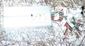
IMG_6414.JPG


First, a quick review of this controller, including a quick test on one of the bikes (later today if possible). Then onto the modifications/upgrades. This controller is from/for Migueralliart from this thread:
http://www.endless-sphere.com/forums/viewtopic.php?p=639963#p639963
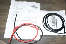
and he has also sent the wire and power/phase connectors that will be used to replace the ring-terminals/cables presently on it. FETs are still on their way.
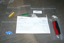
IMG_6317.JPG

IMG_6319.JPG


Apologies for some of the pics, I am still learning how to use the Rebel camera from GMUseless--it's much better than the Sony but is notably different in how it works in a few significant ways. :oops: If anyone needs better pics of something let me know and I will probably have figured out how to get htem by then.

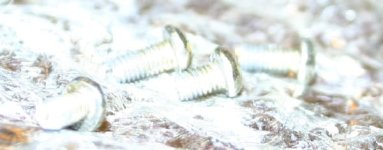
Prior to modding it, I will test it to see if it even works, as it is new/untested, but prior to the test I thought I should open it up to verify it's assembly/etc., since it already was missing 1 screw off the wire-end cap and another was loose in the shipping bag. Plus I was curious. :)
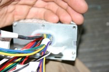
IMG_6318.JPG


View attachment 17

IMG_6434.JPG

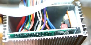
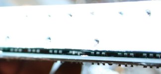
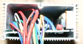
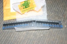
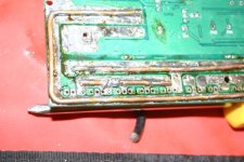
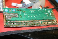
Seems to ahve been a good idea, since I immediatley found two problems. The first is that they didn't bother to actually mount the FET heatsinkbar to the case, they just kinda crossthreaded the screws partly into the holes and left the bar catawhumpus at an angle with only the very bottom edge touching the case. :roll:
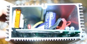
IMG_6418.JPG

IMG_6419.JPG

IMG_6424.JPG

IMG_6425.JPG


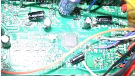
Next they left at least one SMT resistor (102 value) just floating around in teh case, or rather, stuck to the PCB's surface rather than in it's proper place and soldered down. I *hope* it is just an extra, because I don't see any specific place it should go, after a few minutes' examination. I did see two places it could go, but they appear to be deliberately unpopulated.
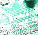
IMG_6429.JPG


He already marked the wires he knew what they were for, but some are a mystery. I think some may be for the same purposes as thsoe on this 36V controller I tested out here:
http://www.endless-sphere.com/forums/viewtopic.php?f=4&t=21830
but not all of those were determined yet, either. I poked around a bit on ES and didnt' find this specific controller yet, but I didn't spend all that long at it. I will make a chart for which pads go to which wires and connectors later, for reference when modding it and to determine if any can simply be removed for simplification, and if any need to be added for his purposes.

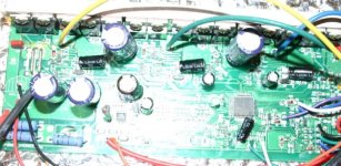
PCB is marked "VP1000A_AVERGER_1.1". Outside label mentions "Sunny" for manufacturer.
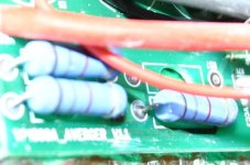
IMG_6436.JPG


FETs aren markked "RU7588R"
http://www.alldatasheet.com/datasheet-pdf/pdf/446158/RUICHIPS/RU7588R.html
75V 80A 7mohm, Vgs=10V Ids=40A Is (Diode continuous forward current)=80A. I might be misremembering, but most FETs use the Ids for their current rating, not the reverse-biased diode rating. :roll: Max Power dissipation at 100C is listed as 75W (150W for ambient but that's useless here).
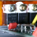
IMG_6445.JPG


Main and phase Caps are 100v 220uF, and the available slots for them aren't all installed either. There are a pair fo wires listed as "volt meter" taht go directly to where a third main input cap should be, for isntance.
View attachment 12


Some of the labelled PCB pads:
View attachment 8

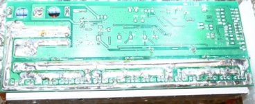
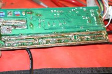
They did sort of beef up the traces but the wire used doesn't actually go far enough, and I think i tis just sitting in the solidified solder, rather than being mounted to the traces. I've seen much worse on other controllers though.


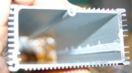
I attempted to get the heatsink bar to mount flush with the case, but since the put the holes at the bottom of the bar instead of the middle, the holes are already crossthreaded at a severe angle, and the PCB/heatsinkbar is too wide to fit in the case with the bar correctly vertical, I can't get it to mount fully flush--only partly. I will have to drill new holes in it across the middle of the bar, and figure a way to tap them, or have the bolts come all the way thru between FETs and then use a clamping bar/nuts to secure it. I also will probably have to either sand the edge of the PCB or the back of the heatsink bar to get it to fit properly. I had to use visegrips at each end of the bar to clamp it to the case while I put the screws in just to get it as flat as it is. :roll:
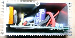
IMG_6448.JPG

IMG_6449.JPG


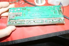
Heatsink bar, failure of it to contact casing enough to do much of anything, fet clearances, other PCB shots, etc. Also heatsink bar screws are not all the same length, and some holes are stripped out from the crossthreading:
 

Attachments

  • IMG_6426.JPG
    IMG_6426.JPG
    15.4 KB · Views: 5,768
  • IMG_6432.JPG
    IMG_6432.JPG
    17.3 KB · Views: 5,768
  • IMG_6438.JPG
    IMG_6438.JPG
    54 KB · Views: 5,768
  • IMG_6441.JPG
    IMG_6441.JPG
    62 KB · Views: 5,769
  • IMG_6447.JPG
    IMG_6447.JPG
    23.2 KB · Views: 5,768
Looks like this may be the same manufacturer as Flez1966's "Boleee" unit:
http://www.endless-sphere.com/forums/viewtopic.php?f=2&t=44040
it is VERY similar in layout and component choices, as well as case style. No ohter info yet, i've got to go to work today so probably nothing new till tomorrow.
 
amberwolf said:
Looks like this may be the same manufacturer as Flez1966's "Boleee" unit:
http://www.endless-sphere.com/forums/viewtopic.php?f=2&t=44040
it is VERY similar in layout and component choices, as well as case style. No ohter info yet, i've got to go to work today so probably nothing new till tomorrow.
Hey amberwolf.. in the picture I counted 15 fets is this a 12fet or a 15 fet?

Did you ever got to test it out as is to see if it works at all. I'm searching around for some genuine 4110 fets in the USA for this controller. I can't yet find anybody in the forum that has em so I'll have to order them from digikey or some other link I saw that methods posted. I'll keep you posted.

BTW when it comes to document stuff you sir are king.....
 
migueralliart said:
Hey amberwolf.. in the picture I counted 15 fets is this a 12fet or a 15 fet?
DOH. 15FET. Fiksed. :oops:

Did you ever got to test it out as is to see if it works at all.
Not yet. That was planned for today but life got in the way again, so tonight it might get a power up and tomorrow a ride.


BTW when it comes to document stuff you sir are king.....
I try, but I leave out a lot of details sometimes, that I often wish I had put in at some later point when I need the info.
 
Note that there is a HVC in this controller, so if you want to go 24s (didn't test anything between that and 16s) you'd probably have to change the lvc/hvc resistors.

Also this controller is really painful to work with. But if it makes your life easier and the hall combos aren't working. Flip the bike over so the hub is free, power off the controller and connect the white single wire jumpers: Thats the self learning mode. If it spins up in the correct direction unplug the wire wire and power cycle, if its the wrong direction unplug and plug the white wire, and if it clicks a couple times and starts flashing an error switch the hall combo around.
 
The plan is to run this controller at 20s with as much current as possible.

If it works ... it will be installed in a kmx typhoon - 20" hs3540 from methods and 16ah made out of lipo 5s packs. I will also be building a bigger 24s5p pack from a123 m1 cells but that is in the back burner right now got too many projects running at the same time plus work is killing me too.

Btw this controller works sensor less too
 
migueralliart said:
The plan is to run this controller at 20s with as much current as possible.

If it works ... it will be installed in a kmx typhoon - 20" hs3540 from methods and 16ah made out of lipo 5s packs. I will also be building a bigger 24s5p pack from a123 m1

why not just run it with solder on the shunt. Your 3540 is going to go before the controller.

migueralliart said:
Btw this controller works sensor less too

Did you get it to run sensorless? I never got sensorless to work, neither did skeetab. I was really disappointed in this controller, poor qc and horrible fets. I thought that it was going to be another hua tong clone, guess not
 
pretty sure the controller could do that without too much problem stock
 
First test of cotnroller ok as a sensorless, unloaded on the Fusin Test Bike's front fork, bike upside down, using the front GM1000W stator & 9C covers from Icecube57 and the 20" 9C wheel from Dogman. I don't have the hall wires run out thru the axle for that one, so sensored test will have to wait for me to mount up the rear MXUS from Ohzee in another plain bike frame. (cuz I don't want to take the Fusin off to do this; taking the front QR wheel off was easy).

Only hooked up battery wires, "ignition" wire (unlabelled red wire with eyelet terminal), and phase wires. Then plugged the white "learn" wires together to make it spin, unplugged them and it stops, replugged and it reverses, unplug and stops. replug and forward again.

While it was running the last time I used a leather glove to load it down some, it had plenty of torque as I coudl not stop it or even slow it much.

LED blinks in a pattern (didn't count them) presumably because it has no halls or throttle hooked up.

Am looking for the throttle I had around here that had the same connector on it (all the ones I can find have the JST type rather than the Tamiya/whatever they are). If I dont' find it in a little bit I'll just splice on a connector to one of my others that will fit; I think I have one on an old dead controller.

More later.
 
Skipped the upside-down frame test with the MXUS and went straight to the CrazyBike2 test. I didn't have the mating connector for throttle or halls except on stuff I didn't want to cut it off of, so I just stuffed the wire ends down into the female connectors on the controller for the test, whcih worked fine.

I just hooked up phase and halls from the 9C in blue-blue green-green yellow-yellow for both, which I know doesn't work on any of the controllers it's been used on so far, to test the learn function with ahlls since it worked fine wiht sensorless. First I put wheel off ground by tilting the bike, then touched the throttle just a tad, and it spun forward but grindy with high amps, indicating a wrong phase/hall combo.

Then I connected the white learn wires; the wheel went backwards (smoothly, low amps) first, so I disconnected and reconnected it and it worked forward, low amps, and disconencted it. Put the wheel on the ground and hit the throttle a little, and it easily pushed the bike forward normally.

Strapped the controller down,
View attachment 2

and went for a quick ride aroudn the local block, with no incident. Acceleration is almost as good as with the Methods 18FET, probably the 9C is being put into saturation with the current the Methods unit provides (over 80A battery) so it isn't putting much more into torque than this unit does, at almost 55A peak current and about 36A or so the first second or two of startup. (tells me maybe I should pull a shunt out of the Methods unit and save myself some power and overheating. ;))


I hooked up my ebrake wires to the black/white wired two pin connector on the controller, as that works fine to cut off motor power, but it does not perform regen, even if you move the throttle while holding the brake, etc.

However...if you stop completely, keep holding the brake handle, and then move the throttle, you get reverse! Was a surprise the first time, but it could be really handy on a trike, as long as you aren't prone to holding your brakes at an intersection and then starting to hit throttle before letting off the brakes. :lol:


Peak wattage (calculated) was 3383W, but that was just the instantaneous; the highest I saw on screen was about 2.2KW.


The motor was fairly warm, but not all that hot, but the controller itself was very very warm, nearly hot, after only a 2 minute ride start / stop ride around the block. The reason could be the FETs or could be how they are driven; if they have insufficient gate drive for the number of FETs they will get hot even if they have good RDSon.


I compeltely forgot to unplug the halls and test it sensorless on the bike; will do that later after I eat.


I'll have to explore the other pads to see which, if any, can enable regen.

Then it's on to replacing the FETs with the "4110"s that showed up today, beefing up traces, and replacing the phase and battery wires and connectors with the larger gauges provided.


On the left is one of the FETs that arrived today, and on the right is a FET out of some I got from Methods quite a while back. If I can and have time I'd like to test the RDSon using the Sorenson as a current supply, and compare it to the Methods-supplied 4110, as well as one of the original FETs out of the controller.
View attachment 1


IMG_6473.JPG
 
how to you wire and test the fets for the Low Rdson ? kindly show the wiring indication instead of drawing. so i think i can understand better. thanks AW
 
Same way you set up a shunt in a controller for testing it's resistance to get the calibration value for a CA. :)

First, heatsink the fet well, so it can dissipate whatever power you're going to put across it.

Hook up a variably-current-limited variable-voltage lab power supply across the FETs, + to Source, - to Drain. Set current limit to say, 10A. Make sure the voltage is set to less than the max the FET can take. Doesnt' have to be very much--1V is probably enough, or 10V, or whatever. If you have a charger that has a constant current mode (wire cut?) then you can use that.

Hook up the Gate to separate power supply set to a voltage that guarantees full turn on (usually 10V, some only need 5V, check the datasheet).


Measure the voltage you actually get across the FET, then divide that by the current (10A) and you have the resistance.

The higher the current you use thru the FET, the more accurately you can measure the RDSon with cheaper voltmeters, but also the more power you end up dissipating thru the FET during the test.
 
I guess I dozed off b efore I posted the test results for sensorless: It won't work.

I first tried just disconnecting power on the halls and just hitting throttle, nothing. Hooked up the learn wires, and it spins up (reverse first, disconnect/reconnect gives forward), retried throttle, nothing. Off ground same thing. Powercycled, same. Disconnected all hall wires and powercycled, same, as well as retrying the learn wires, to no change.

It only responds to the throttle with the halls connected.

Additionally, it will respond once the halls are connected *wihtout* redoing the learn function. So the learn function just figures out the phases and the MCU's code must be smart enough to "figure out" the hall sequence from there, with it "assuming" the rotor is spinning in the right direction once the phases start firing.

So, interesting, but not precisely helpful, if one wants to run it sensorless. If it is supposed to be a sensorless-capable controller, I haven't figured out how that should work yet.
 
The first test was only using the learn wires to run it, unloaded off-ground. I didn't have any throttle hooked up to the controller at all at that point. I guess the post wasnt' that clear. :oops:
 
Huh? So it learns correctly but won't respond to throttle if there are no halls plugged in? Mine would just twitch a couple times and give up during the learn.
 
Ok, so this is the text, with my inline translations of the translation.

Quad dual-mode controller
No idea what "quad" means here; there aren't four of anything relevant in it or four functions, unless they mean 4-quadrant (because it is reversible and should have regen)

First, the controller functions
1. Self-learning: With Hall sensor or without Hall sensor automatic recognition, automatic phase identification, automatic identification the undervoltage.

The self-learn function does work to learn either way for motor direction, dunno about automatic LVC. Can't figure out how that would work.

Well, actually, if it is for a specific battery chemistry, it's relatively easy. If it assumes you use the learn function when the pack is at full charge, it could take taht voltage and divide it by the full cell voltage of the specific chemistry it was made for (probably SLA, maybe LiFePO4) to get the number of cells of the pack, then set the LVC to that number times whatever tehy decided should be the cell-level LVC.

2. Power / Reverse: Power / Reverse
I assume this means the function I found where you get revers if you throttle while holding brake, from a stop.


3. Cruising at constant speed function. When you are riding speed cruise speed appropriate, click the button, the speed to automatically loose his driving, get off the brake when not required, or press the cruise button on the lift
I'll have to find the pad to trigger the function, but it sounds liek a typical cruise, so you can let off the throttle after engaging it, and disengage it by braking or pressing the button again.


4.EABS electronic brakes, electronic brake signal when the program started off at the same time to achieve rapid braking effect.
That's pretty apparently the regen braking, but have to find the pad to trigger it.

5. The speed limit: speed limit.
I don't know how this would work, it certainly isn't very limited now (about 45MPH off-ground speed with a 9c 2807 in a 26" wheel). perhaps there is another jumperable pad set to engage this.

6. Burglar alarm: alarm in the alarm works, it will automatically lock the motor.
this sounds like the common function several types of controllers ahve. It may be one of the wires already brougth out, as I seem to recall that function on the other controller with similar connector wiring patterns.

7. Third gear speed: high, medium and low speed of the points.
must be the three-speed switch, have to find the pads for it. Proably just two pads and ground, like many others.


8. Electronic brake: when you brake a Hall sensor signal line passed to the controller then the controller automatically stops the motor immediately stops the motor power supply.
this already works, and is the black and white two-pin connector. it just cuts off the motor, not actually braking it.


9. Dual undervoltage: two less points, 42V and 38V. Also called standby power.
This I don't understand.


10. Automatically compatible with Hall sensor without Hall sensor
This part doesn't seem to work; I assume it means it will automatically fallback to sensorless if it cant' get good signals from the sensors.


11.1 seconds to complete the learning
This appears to be true (or less time, even).


12. Motor short circuit open circuit automatic protection prevent damage to the power tube
Maybe has a fusible trace on the PCB for the power input, as that's the only thing I can think of that would prevent battery damage by motor/FET shorting.

13. The real protection against runaway
No idea what that means.


Second, the use method
Connected to the controller, open the electric door locks, two white lines short circuit, the controller into the learning state;
When the motor hall sensor is normal , motor high speed operation, then into hall sensor running mode;
When the motor Hall sensor failure, motor low speed operation, into the without Hall sensor mode;
If the motor reversal, unplug the white line and then plug it again, the motor is corotation;
Unplug the white line, study completed, enter the normal working condition.
The motor during normal operation, Hall sensor damaged, the controller automatically into the without hall sensor running mode, to ensure the normal riding, when the Hall sensor is restored, the controller will automatically go into a Hall sensor running mode, to ensure optimum operational property.
Hall sensor damage when the motor at rest, push the car 1-2 meters, the controller automatically into without Hall sensor running model


Ok, that all makes a bit of sense. I will go try manually spinning the wheel without halls and see if it works.

Does seem odd that it only uses sensorless as a fallback and wont' use it as it's first normal mode of operation.


It is interesting that it keeps using the word "car" in there; I suspect they meant "vehicle", for scooter or ebike, as this thing is not powerful enough to move a car (except with very high reduction on a high RPM motor, but not at a very fast road speed).
 
Tested the 20" wheel using thsi controller, before testing it with the Methods controller. Works well; would be more "impressive" with immediate start instead of soft start, but it's still pretty good.
http://www.endless-sphere.com/forums/viewtopic.php?p=646635#p646635

Max off ground speed with a 20" wheel on 16s is ~35MPH.
 
Life has gotten in the way an awful lot lately; I have not yet gotten the PCB pad vs function determinations or the power upgrades done. :(

I thougth I broke the controller a few days ago when I started work on it again, but tonight after poking around at it I found all that was wrong was the power wire may be broken just inside the crimp with the original ring connector. If I push at it a bit it connects and works. Doesnt' matter as these are coming off to put andersons on, but it is annoying as I might have accomplished something tonight if it hadn't happened.

It's holiday season already at work, so it's pretty hectic and stressful; I work six days this week, but hope thursday (my day off) to get on this again.
 
Didnt' get to this last week, but am working on it now (for almost the last three hours, taking a short food break now).

Am in process of removing all the wires that are being upgraded (phase and battery), and installing the new wires and connectors (including adding a CA connector). Have also removed all the "unknown" and unused wires/connectors, after noting down where they previously were soldered to the PCB.

Removing the excess solder and such off the FET power supply traces, too, in preparation of adding the 12G solid-wire "beef-up", which will be first clamped to the board then soldered between the clamps, then clamps moved/removed and full soldering done. Where possible I will run the beef-up wires down into existing thru-holes in the traces, or "tie" them down to the traces with wires across them. FET removal will happen before that, and install of new FETs afterwards, so they aren't overheated by the trace-beef-up.


Made a list of all the used and unused wire point pads on the PCB, with (known) and [guessed] functions, as well as {present wire colors}.

(JTAG1: 4-pin)
+
?
?
?

P07
P37
P36
P43
P41
P40

EBS [enable regen braking]

TS (Throttle Signal Input) {green throttle wire}
XS
XX (Learn Function) {1st white learn wire}

BL [engage brake, grounding version]
BH [engage brake, +5v or VCC-input version] {single purple wire}

VV5 (+5V)
VV6 (+5V)

VV4 (+5V)
VV3 (+5V)
VV2 (+5V)
VV1 (+5V) {throttle red wire}

VCC4 (Battery + distribution bus / ignition wire) {orange wire mystery 3-pin}
VCC5 (Battery + distribution bus / ignition wire) {keyswitch red wire}
VCC2 (Battery + distribution bus / ignition wire)
VCC3 (Battery + distribution bus / ignition wire)

RX [serial for handlebar display]
TX [serial for handlebar display]

FD {blue wire mystery 3-pin}
DD {white wire mystery 2-pin}

H5V (hall power) {red hall wire}
HU (hall U phase) {green hall wire}
HV (hall V phase) {blue hall wire}
HW (hall W phase) {yellow hall wire}
GND (hall ground) {black hall wire}


(GND 10 pins) {black wire mystery 2-pin}
(GND 10 pins) {black wire throttle}
(GND 10 pins) {2nd white learn wire}
(GND 10 pins)
(GND 10 pins)
(GND 10 pins)
(GND 10 pins)
(GND 10 pins)
(GND 10 pins)
(GND 10 pins)

-SD
SD {yellow wire mystery 3-pin}

LO2
LO1
HI1
HI2
1:1
XH


Anything left without a guess or a function name, I just don't know yet, and will have to add wires to them to try testing their functions.
 
Time for another break; dogs are really bored and my hands and eyes are cramping. Cramped eyes really suck. ;) Have you ever had a charlie-horse in your iris?
IMG_6571.JPG

I have the beefed-up traces done, though they didn't turn out exactly like I wanted them to, they are sufficient for the purpose. :)

The phase wires are also installed, but connectors have yet to be put on.
IMG_6574.JPG

Previous stages:
IMG_6573.JPG
IMG_6572.JPG

Before soldering, main two traces
IMG_6568.JPG


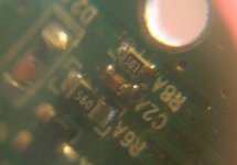
In the process of prepping the 12g solid wire for install, I managed to crush C2A, one of the gate drive capacitors for phase U. :( As I don't have anything that seems able to read the cap value (despite several DMMs that purportedly can do so, none is consistent with any other, nor do they read twice the same themselves!). I didn't expect a perfectly accurate value, as I was measuring each of the other phases' driver circuit caps in-circuit, but I had hoped to get close.

So I just took an old dead 9FET and "blindly" pulled a cap from the same circuit area, though it is not the same design it may be a close enough value. Took nearly half an hour just to get the cap off of there, cuz my fingers just don't work right. Then I managed to lose the cap just as I was about to touch it with the soldering iron (holding it place with a penknife), sending it flying somewhere I'll never find. :roll: about 15 minutes later I had a cap from another phase of the 9FET off and maybe 10 minutes later I had it ready to solder, this time managing to actually do it.
IMG_6566.JPG


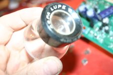
Had to take the pic thru the eye loupe, cuz I couldn't get it to focus close enough.
IMG_6567.JPG


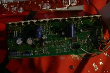
The board before FET removal
IMG_6563.JPG
View attachment 8

FET removal took quite some doing, with numbers of burned fingers, because for some reason they are very tightly in the holes. Either the holes are smaller than normal, or the legs are larger. Normally I cna just soldersuck the legs mostly clear, then hold my centimeter-wide chisel tip 80W Weller iron against the pads and leg tips on the bottom, PCB upside down, and the FETs will fall out. This took me trying to hold the iron in place and pull the FET out, which had to be done with fingers cuz I couldn't hold them with pliers or anythign else; kept slipping out.


Also, note how poor QC the FET install to heatsinkbar was--they didn't even put paste on most of the FETs, and it's like that on the other side of the Kapton, too--just dabs here and there. :roll:
IMG_6559.JPG


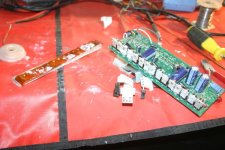
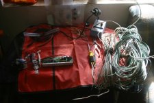
And the table setup earlier today, to start the soldering, after documentation and finding all the parts, and the old house wiring to be stripped for the solid wire, since the insulation is old and dry-rotted:
IMG_6558.JPG
The orange static mat is actually Mdd0127's, left here by accident a couple of visits ago, and forgotten by both of us each time he's been back by. :( I forgot it was even here till I ran across it today.
 
Not gonna be anything more tonight; still too wiped to concentrate effectively on it (have been dozing off and on while trying to eat dinner and read ES since the above post. Burned some of dinner when I dozed off cooking! :oops:). All I could do was put all the little bits into containers for the night, to keep dogs and doggie fur out of them. :) Hopefully get some more done before work tomorrow (maybe after but probably not), and/or after work Sunday.
 
After last week being a wash to get anything done, I tried today to finish this up, but my hands are not working right--neither is my brain, apparently. I started wiring up some test wires to all the signal pads that we dont' yet have verified functions for, but couldnt' seem to get the solder to stick right, even though it melted fine on the iron for tinning. After more than an hour of trying over and over I finally realised the adjustable iron was set to only half power, which I guess is just barely enough to make solder melt for small-gauge wires on signal pads. :(

So I thought I shoudl take a break from that, and fix some dinner, which turned out a failure too (got distracted, and burned some of it...still edible but not what I'd hoped for).

Still not ready to go try soldering again, I went to another project, but screwed that one up, too.
http://www.endless-sphere.com/forums/viewtopic.php?p=676206#p676206
http://www.endless-sphere.com/forums/viewtopic.php?p=676208#p676208

I guess today is just not a good day to work on stuff. Perhaps tomorrow will be better.
 
Back
Top