Science, Physics, Math, & Myth

That "W" is no typo, and it really means watts of electrical power input to the motor.

I missed that gem of a post from Miles. How awesome.

If you just have Km and Kt (which we do for most motors) we can compare exactly the cost of power to make a given amount of torque in a ton of motors. On top of this, if you add the no-load power vs RPM (which can be measured easily with a CA) , you can calculate nearly all situations the motor can be in (with the exception of when the motor's core saturates). For example, in one of my hubmotor dyno vids, the motor makes something like 10.2hp at 15kW of input power. At 40kW it made 10.5hp and lots of smoke, and this type of simulation won't help you find that data.
 
liveforphysics said:
That "W" is no typo, and it really means watts of electrical power input to the motor.

I missed that gem of a post from Miles. How awesome.

If you just have Km and Kt (which we do for most motors) we can compare exactly the cost of power to make a given amount of torque in a ton of motors. On top of this, if you add the no-load power vs RPM (which can be measured easily with a CA) , you can calculate nearly all situations the motor can be in (with the exception of when the motor's core saturates). For example, in one of my hubmotor dyno vids, the motor makes something like 10.2hp at 15kW of input power. At 40kW it made 10.5hp and lots of smoke, and this type of simulation won't help you find that data.

The Dynometer is the way to get the real data you need. I present this photo as evidence and rest my case.
 
John in CR said:
Oh crap, I need more help. Miles has Km motor constant: Kt/√W as well as Km = Kt / √(Rm). Rm= phase-to-phase resistance in ohms...I get that, but what is W, or does one have a typo? source http://www.endless-sphere.com/forums/viewtopic.php?f=30&t=45489&p=663544#p663606
Miles said:
Jeremy Harris said:
It's normally the square root of the rotational speed, W, in rads/S, where 1 rad/S = 57.2958 degs/S or about 377 rpm.
Which shows what a minefield motor terminology is. In this case, as it's upper case, it was meant to stand for Watts. It would have been better if I hadn't made the abbreviation.....
Miles said:
John,

All you need to know is that Km is a measure of the relationship between torque and the heat generated to achieve it.

Take your torque constant (Nm/A) and divide that by the square root of the phase to phase resistance (Rm).

Km = (Nm/A) / ✓(Rm)

If you want to compare motors relatively, divide Km by the motor weight in kilograms to get "specific Km".
http://www.endless-sphere.com/forums/viewtopic.php?p=668524#p668524
 
Miles said:
It would great to factor in a value for the parasitic losses, so as to arrive at an overall figure of merit, but I can't see any way to...

I'm still trying to wrap my heat around Km, because torque in Nm per the square root of Watts doesn't make much sense to me at all. Your addition to make it specific Km definitely helps level the playing field for different size motors, but when every other rating number makes sense the Km comes along and I'm WTF? I know you like to use Nm/kg, but continuous current ratings are made up numbers. Sure there can be educated guesswork involved, but it varies too much with usage and conditions such as rpm, voltage, ambient temperature, vehicle speed, motor placement, etc.

I don't want one number. Instead I want all of them, and not just weight as the only physical dimension. I want stator length and diameter along with weight.
 
Rix said:
The Dynometer is the way to get the real data you need.

Great idea. Let's start with those Xlytes you have. Don't forget to include the Kv, Phase resistance, and no-load current with rpm, so we can compare numerical analysis to the dyno results.
 
John, I've just been puzzling other this a bit, too. This is my take on it:

Kt gives use the torque per amp, but is obviously dependent on the winding.

Km tells us (as per Luke's .pdf link) how effective a motor is at converting electrical power into mechanical power. This being independent of the winding configuration (as we know from this very thread :D ), so it must also account for voltage, hence incorporating the winding resistance.

It is odd to see units of a measurement include a square root, but I suspect this is simply the inverse of the P=I^2R relationship.

Maths is one of those things that isn't intuitive to me (I prefer thought experiment) but I bet Km would become very clear if derived step-by-step from first principles.
 
John in CR said:
Rix said:
The Dynometer is the way to get the real data you need.

Great idea. Let's start with those Xlytes you have. Don't forget to include the Kv, Phase resistance, and no-load current with rpm, so we can compare numerical analysis to the dyno results.

That's not necessary, you talked me out of bragging about the 5404 a couple of pages back :mrgreen:
 
John in CR said:
Rix said:
The Dynometer is the way to get the real data you need.

Great idea. Let's start with those Xlytes you have. Don't forget to include the Kv, Phase resistance, and no-load current with rpm, so we can compare numerical analysis to the dyno results.

Crystalyte has made a lot of motors and I've had the (mis)fortune of being quite familiar with and done a lot of direct measurements on most of them.

Here's a few to feed the table, with pairs from the same series but with just different stator/magnet widths. I'm interested to see how that fairs out in the Km normalization:

TC3080
Mass = 7.45 kg
kt = 0.95 Nm/A (with trapezoidal drive, about 1.03 Nm/A with FOC)
Rwinding = 0.115 Ohms (room temp)
Core Loss Drag = 1.11 Nm + 0.018 Nm/Rad/Sec

TC4080
Mass = 9.02 kg
Kt = 1.023 Nm/A
Rwinding = 0.0887 Ohms (room temp)
Core Loss Drag = 1.66 Nm + 0.03 Nm/Rad/Sec

Crystalyte 20mm SAW Motor
Mass = 3.48 kg
Kt = 0.700 Nm/A
Rwinding = 0.231 Ohm
Core Loss Drag = 0.366 Nm + 0.006 Nm/Rad/Sec

Crystalyte 40mm Saw Motor
Mass = 5.44 kg
Kt = 1.09 Nm/A
Rwinding = 0.288 Ohm
Core Loss Drag = 0.73 Nm + 0.0065 Nm/Rad/Sec

Someone want to crunch the numbers and see how these stack in a purely normalized Specific Km sense?
 
Miles said:
justin_le said:
Someone want to crunch the numbers and see how these stack in a purely normalized Specific Km sense?
Ok, I'll start a spreadsheet.

I can take measurements and provide phase resistance for Zero motors tomorrow.

Justin- To keep all data normalized, can you let us know the location you sense the voltage when taking your kelvin reading for phase resistance? At the phase lead exit at the axle? At the winding to phase lead connection ?
 
liveforphysics said:
Justin- To keep all data normalized, can you let us know the location you sense the voltage when taking your kelvin reading for phase resistance? At the phase lead exit at the axle? At the winding to phase lead connection ?

Good question. All the phase measurement resistances were done by putting 10.0A of current in through a pair of the phase windings via the motor leads and measuring the voltage drop on the back end of the anderson connector of the motor cable. So it includes the lead resistance of the wire going through the axle, but we have all of our motors spec'd with a relatively short cable exit from the axle to the connector (typically about 20cm) so there isn't a long lead length of wire here to add much resistance.

For characterizing the motor proper it would be best to measure it right at the stator, but the actual motor people use includes the wire leads coming out of the hub and their associated losses, and this is one of the reasons that in practice people do experience somewhat higher torque with slower wind hubs. So I think for the sake of the comparison table it makes sense to include the supplied motor cable losses in with the winding resistance. It's easier to measure and more reflective of the experienced performance, (well for all except the hard core modders like you who manage to stuff 10awg wire through a 9C axle)

-Justin
 
That's fine, I will measure the Zero's motor at the ends of the phase leads as well, and they bolt straight to the controller so it's the whole path. The phase leads are just a couple added feet of 1awg anyways, so it's ~0.3mOhm added which doesn't make much of a difference.
 
justin_le said:
For characterizing the motor proper it would be best to measure it right at the stator, but the actual motor people use includes the wire leads coming out of the hub and their associated losses, and this is one of the reasons that in practice people do experience somewhat higher torque with slower wind hubs.
Also:
Miles said:
The end turn losses are constant for different winds. The only thing that varies is the relative resistance of the section of copper between the coils as this changes in cross-section but not in length...
 
Temperature correction may also be required?

This article: http://www.endless-sphere.com/forums/download/file.php?id=95992 quotes the following:

Heating of the winding will further reduce KM since copper resistivity rises almost 0.4% per degree °C. Just to
exacerbate the problem the magnetic field will attenuate with rising temperatures. Depending on the permanent
magnet material utilized this could be as much as 20% for a 100°C rise in temperature. The 20% attenuation for
100°C magnet temperature rise would be for Ferrite Magnets. Neodymium-Boron-Iron has 11% or more, and
Samarium Cobalt about 4%.

It might make a significant difference for people taking measurements in different parts of the world. Or it may just be an interesting comparison of how a motor's performance changes as it warms up i.e. Km @ 20°C Vs. Km @ 100°C

Where 20°C is usually considered "room temperature" and 100°C is perhaps as hot as you would like a motor to get in use.

Or is this pointless as all our motors tend to use the same type of magnets and so will all be similarly affected?
 
justin_le said:
Here's a few to feed the table, with pairs from the same series but with just different stator/magnet widths. I'm interested to see how that fairs out in the Km normalization:
 

Attachments

  • Justin's-motor-data.jpg
    Justin's-motor-data.jpg
    25.9 KB · Views: 3,283
Hard data. Now that's what I like to see.
Is a dyno required to take the measurements, or just a consistent power source and a good multimeter?
 
Miles said:
Anything else?

I'd like to see at least 1 no-load current and it's rpm. If there's a manufacturers rated power and it's voltage, it could be useful as at least an estimate for calculating it's continuous torque. For the Kv and no-load current room to notate if it's with a wheel on, since for some of the more obscure motors we may not be able to get measurements without a wheel, and it makes a significant difference. Might as well add stator lamination thickness, motor inductance, and peak efficiency at a stated voltage too so they can be listed if available.

Maybe as part of this process we can come up with a better formula for a motor constant. The specific Km may make comparisons between motors seem better, but I have reservations about Km being a useful number at all. It's definitely not the great equalizer as claimed in one of the links. Resistance squared isn't meaningful, so a formula using the sqrt of resistance can't be either, nor can the sqrt of a watt.
 
teslanv said:
Is a dyno required to take the measurements, or just a consistent power source and a good multimeter?

No need for a dyno at all. You can pretty much fully characterize the non-thermal and non inductive aspects of a motor by doing the following:

1) Put a known current through a pair of phase wires and measure the voltage with a multimeter.
2) Measure RPM and no load amperage at full throttle at one voltage V1
3) Measure RPM and no load amperage at full throttle at another voltage V2

From step 1, ohms = multimeter volts / power supply amps

From steps 2 and 3, you have kT1 = (V1 - I1*R)*60/2Pi / RPM1, and kT2 =(V2 - I2*R)*60/2Pi / RPM2

both kT1 and kT2 should be basically identical, and average them for your kT in Nm/A (or if you prefer, your kV in V/Rad/Sec)

From steps 2 and 3, you also have the core drag, which is pretty linear with RPM. So you do a straight line interpolation

The drag torque at RPM1 is just kT * I1, and the drag torque at RPM2 is kT*I2, call these Trq1 and Trq2

The drag torque at 0 RPM is (RPM1*Trq2 - RPM2*Trq1) / (RPM1 - RPM2), this is effectively the hysteresis drag from the iron core changing polarity, and is constant regardless of speed
The dependence of drag torque on RPM is the slope: (Trq2 - Trq1) / (RPM2-RPM1), this is effectively the drag caused by eddie currents, which is proportional to your RPM

So now you know the drag of the motor at any given RPM, you know how much torque and heat the motor will produce for a given current, the RPM it will spin for a given voltage, with just a couple quick measurements and no fancy test equipment.

The winding inductance and number of poles plays an important role in the actual shape of the torque vs rpm curve, at least with a non field-oriented controller, but it has little effect on the motor efficiency so these can be ignored for now, and are not a factor in this specific Km model.
 
Km is what it is. It compares copper loss to make an amount of torque.
 
Is this method of determining Km applicable to brushed motors, too?
 
John in CR said:
I'd like to see at least 1 no-load current and it's rpm.

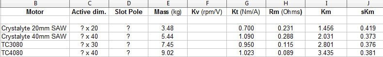
We've indirectly published the effective no load current and it's dependency on RPM for all the motors in the "specifications" tab of each motor on our site:
Hysteresis and Eddie Losses in Spec Tab.jpg

The problem with specifying it as an amperage is that it then becomes dependent on your particular winding. A fast wind motor will have higher no load amps at a given RPM than a slow winding of the same motor, since it needs more amps to achieve the same torque. So it's better to scale the no load amps by the motor's kT term and express it as a no-load torque, and this way you'll get the same results regardless of the winding.

In the above example, a hystersis loss of 0.37 Nm and an eddie loss of 0.006 Nm/V means that the motor drag at 300 rpm would be:

0.37 Nm + 0.006 * 300 rpm * 2Pi / 60 = 0.558 Nm

And since it has a motor kT of (60 / 2Pi /13.6 RPM/V) = 0.702 Nm/A, then the no load current at 300 rpm for this wind would be 0.558 Nm / 0.702 Nm/A = 0.794 amps.

If there's a manufacturers rated power and it's voltage, it could be useful as at least an estimate for calculating it's continuous torque.

I think that the point of this exercise is to do away with manufacturer ratings which can be all over the map, and instead of a normalized means of comparing expected motor performance based on measurable values.

If two motors have exactly the same mass and kV, but one has a resistance of 0.1 ohms, and the other has a resistance of 0.2 ohms, it's clear that the 0.1 ohm version is a *better* motor design, it will produce less heat for the same amount of torque, and with no extra weight. This would manifest itself by a higher Km. If two motors have the same kV and same winding resistance, but one is lighter than the other, then again the lighter motor is a better design and would have a higher specific Km.

If two motors have the same mass, but motor 1 has a winding resistance of 0.1 ohms and a kV of 10 rpm/V, and motor 2 has a resistance of 0.3 ohms and a kV of 5 rpm/V, which is the better design? In this case, for motor 2 to produce the same torque as motor 1, then it requires only halve as much current since it has twice the Kt. But it has 3x the winding resistance, so the total heat generated for a given torque is 3 * (1/2)^2 = 75% lower. Therefor motor 2 is a better better motor, but unlike the other examples it's not immediately apparent without a formula. This is why the square root of R is so important for equalized comparisons.

Now take two motors that have different masses, different kV's, and different resistances, how do you size up which one is *better*? That's what having a normalization parameters between all these variables would do, which my understanding is the goal of specific Km. If you want to size up a motor to see if it is good for a certain power level, then you take the specific Km and multiply it by it's mass again to get Km, and then multiply by your RPM to get some kind of standardized power capability number.

For the Kv and no-load current room to notate if it's with a wheel on, since for some of the more obscure motors we may not be able to get measurements without a wheel, and it makes a significant difference.

That's a good point, although rather than it making a significant difference, I would argue it makes just a slight difference, especially at the modest rpm's of bike wheels. All of the measurements I have provided are for the hub only, not laced in a wheel.

Might as well add stator lamination thickness, motor inductance, and peak efficiency at a stated voltage too so they can be listed if available.

These are all totally irrelevant in a sense, they are mechanical details but what we would care about is how that manifests from measured motor parameters. Manufacturer claimed peak efficiency at a given voltage is also pointless, you can get that derive for any voltage from the known core losses and winding resistance which are terms we already have.

Maybe as part of this process we can come up with a better formula for a motor constant. The specific Km may make comparisons between motors seem better, but I have reservations about Km being a useful number at all. It's definitely not the great equalizer as claimed in one of the links. Resistance squared isn't meaningful, so a formula using the sqrt of resistance can't be either, nor can the sqrt of a watt.

I think it would work like this.
Km gives the basic power class of the motor.
Multiply the Km by your target RPM to get your actual power capability for that motor at that speed.

We could have a chart that relates how many watt/RPM a given Km motor could produce for a given amount of time before overheating.
 

Attachments

  • Hysteresis Loss for Motors.jpg
    Hysteresis Loss for Motors.jpg
    62.4 KB · Views: 3,178
Miles said:
justin_le said:
Here's a few to feed the table, with pairs from the same series but with just different stator/magnet widths. I'm interested to see how that fairs out in the Km normalization:
file.php

Thanks miles, this is very cool. The Km values quite accurately scale up with the basic motor power, from the narrow 20mm SAW to the large 40mm Crown. The Specific Km values are all remarkably close at about 0.38. So we can perhaps say that this is representative of the Crystalyte motor 'quality' level, in a raw motor performance sense. I do have this information on many many other hub motor types too but it is all scattered among a number of notebooks and test files, so as I dig those up I'll post them here to add to the list.

Miles said:
It would great to factor in a value for the parasitic losses, so as to arrive at an overall figure of merit, but I can't see any way to...

I think this needs to be a separate metric, you can't easily 'lump in' the internal loss value without arbitrarily deciding how much effect it should have on increasing or decreasing sKm. If you have two identical motors both with an sKm of say 0.5, but one has 1Nm of no load drag and the other has 2Nm, it's clear that the 1Nm drag is the 'better' motor and should have a higher sKm value if sKm is some measure of overall betterness, but by how much?

The core losses are a big deal and deciding factor for motor choice when you have an always engaged drive system, and so a similar normalized way to express it would be good. If the motor can output twice the continuous output torque, but also has twice the drag resistance from core loss, then it come out with the same normalized drag coefficient. One way would be to simply divide the drag torque at a given RPM by the Km value.
 
Back
Top