kWeld - "Next level" DIY battery spot welder

"My kWeld's Mod "

This post is about how to make kWeld to work with 0.15mm Ni(Fe) + 0.20mm Cu sandwich reliably at ≈1,7xx Amps @140Joules. If your stock kWeld can do that already, that's perfect. Mine had some problems so I need to fix/modify it. Whole mods cost mostly from material (cables & Cu rod, Cu bar, lugs, etc. ), labor and time. This post is like my own memo for my mods and share to you guys for the possibilities to improve your already high potential kWeld. This is rather a story telling style, bare with me - you might get something useful. Some members struggling with this, please read on.

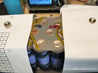
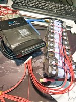
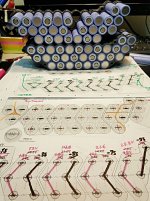
I am building a pack of 20S3P of Samsung 21700-40T for my new DH e-bike (long delayed for years). Though this pack is far from high power, Cu is still preferable than Nickel for its ≈4X better conductivity and if I can weld Cu, it enables me to leap a step toward making big & high current pack. Given that using Cu is as cheap as Nickel but with much better performance. The 0.2-mm minimum thickness Cu is my choice because some ES members used kWeld to weld it before. I thought 0.2mm Cu is almost the limit of current kWeld with regular sandwiching technique, where both probes are on top of Ni(Fe), Cu in the middle, and cell cap at the lowest.


67.png
 
Then, however, I found this post after I prepared all the Cu pads already :

***** Re: kWeld - "Next level" DIY battery spot welder ******
by nuxland » Dec 18 2021 4:16pm

Showing 0.2mm Ni + 0.5mm Cu with each probe on each material - that's different. I'll just call this technique "Tip-Toeing" for ease. But it surely sounds very interesting. It might be a bit hard to push 0.5mm Cu sheet down to touch with cell cap. Plus, my ready-made 0.2mm Cu pads are more than enough for current. May be next time for the 0.5mm Cu. It should be very good for high current pack
 
Why go for minimum when we can be better off with 0.2mm Cu and it will not be disappointing throughout the life of the batt pack. I also used cut-to-shape Cu pads instead of strips to minimize R loss. Vsag from Cu loss when (hard) accelerate (30-40A ?) will also be minimized. On every serial connection (my 20S3P pack needs at least 19 serial connects) - that's not negligible at all. Somebody kind enough to calculate these whole pack serial connections losses if Ni or Cu is used in such pack.

Welding Cu is difficult due to its naturally low R and very good heat conductor, heat is not adequately generated and spread out quickly for less than several thousands of amps through, not enough to melt Cu. Current version kWeld cannot do that directly. Fortunately, some folks discovered sandwiching technique and shared with us. Pure Ni has higher R and generate more heat than Cu, enough to melt itself and Cu next to it. Ni(Fe) has even higher R (it is 100% steel w/ thin Ni coated), so more heat concentrated in that area longer - hot and long enough to melt Cu reliably. That's why we get a better welding results using Ni(Fe). All we need to weld Cu is just very high current in a very short time.

I was using kWeld to weld this pack happily before the accident with my kWeld during 2022.08. That forced me to dig deeper. Most of the mods here were the info I got from e-mailing back-forth with Frank. I am no expert but just finish welding another pack using Cu-Ni as I desired. So, I will be sharing some mods details with ES here. The mods examples, values, setting, and etc. shown here are for my kWeld system. Each kWeld can be different. Be very careful to adopt anything for your own system. Do ask question if you are not sure. The ES experts here will come to help.

My sincere gratitude to those who found Ni-Cu sandwich technique and share with us. This technique enables us to DIY welding difficult Cu. Anyone knowing who that person is, pls share with us.

Special thanks to Frank (Tatus1969) the creator of kWeld for his support, info, and for backing up his products. His kWelds, not just another DIY welder in the market, but show reliable welding result opening a new DIY channel to us.

I might not be very accurate on every detail of this mods but the concept is there. You get the idea. Do correct me anywhere should you find anything wrong. This will be great for academic purposes. Also excuse my language, if not very nice writing style to everyone's like.

Study kWeld and prepare carefully. Spot welding requires very high energy to begin with. Make sure you use safety gears : goggles, mask, gloves, protective shield, insulation cover, etc. for both yourself, other people and properties. Better safe than sorry.
 
My Goal :

To weld Cu, my welder must be capable of shooting high current to reach or close to 2000-A limit using kWeld + kCAP 3S2P Maxwell's 310F 2.7V caps. In this build, I will use 0.15mm Nickel-plated steel tab [Ni(Fe)] and cut-to-shape 0.2mm Copper pads [Cu], both slotted (slits), to weld on top of cell caps.

My definition : a good spot-welding is, after welded, you cannot pull the tabs (Cu and/or Ni) out off the cell cap without totally ripping / damaging it. They must be fused permanently together to full surface of the weld materials covering all spots. I normally weld 3 times for each cell cap making 6 spots. :thumb: :thumb:
 
The Basics :

There are confusions re kWeld's working principle. Joule = energy level set for the weld.

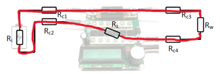
Theoretically, when there is a power source (or storage like SuperCap) = V. Then, there is load (all combined) = R-all, and there is a switch (MosFet of kWeld). SuperCap connects with R-all via a switch, once this switch is triggered, current will flow from SuperCap through R-all with a simple relationship V = I * R. Because we need very high current I and I = Vcap / R-all, then we have to raise Vcap as high, and make R-all as low as possible.

Where kWeld's only adjustable welding energy Joule = Q * t = I^2 * R * t, there is a "t" (duration of pulse) involved. You can also call it "watt-hour" in a more familiar term. For stock kWeld, when we increase Joules, kWeld will determine a "longer" t(mS) for us. Because R-all and Vcap have not been changed, welding current remains practically the same. It does not do much good to weld Cu this way (longer t), even with sandwiching method. Again, we need high amp in very short time to effectively weld low-R / high heat transfer metal like Cu. :?

When high amp together with low t (mS) are both achieved simultaneously, heat will stay concentrate in that spots and cannot escape fast enough = Cu can be fused with cell cap. Since kWeld by default can release 2,000A max by design, this is not enough to melt Cu directly. Luckily, we have an old friend aka "Ni(Fe)" who has higher melting point whom we can ask for help easily. :D

Googling found that Cu melting point is 1085C, while Nickel at 1455C and Steel 1,3xx-1,5xxC. Again, the folk who discovered this sandwiching technique are truly ingenious. They use the concept "Borrowing Ni higher melting point to fuse Cu to cell cap". Just like the old (Chinese) saying goes "Borrow a sword to slash enemies". Brilliant Huh! :thumb: :thumb:

Example :
We adjust Vcap a little (8.1 to 8.2, 8.3, 8.4V) resulting in higher current. Parts of R-all that can be improved are welding cables and probes. The two new modified parameters (Vcap & R-all) will directly increase higher current output, if done correctly. In my case, from 1,2xxA to 1,7xx-1,8xxA from these mods, an increasing of 500-600A. From few mΩ factory default (2.5-3mΩ per kWeld's manual) down to 0.6-0.8mΩ R-all & increasing Vcap. No surprise, we are dealing with sub to a few mΩ here. Small details matter. Without these 2 mods, cranking up Joules will only increase t(mS) where I(amps) remains the same, that will not improve welding Cu much at all. I keep rephrasing explanations here to express the same idea in a different way hoping to give you guys a clearer conceivable scenarios. Bear with me. :x
 
There are ways to connect your kWeld with power source :

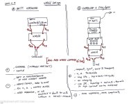
Different power sources : Batt or SuperCap

a) Battery operated kWeld (LiPo / LiFePO4 / Deep Cycle / Marine Batt, AGM, etc.) : the length of supply leads from batt to kWeld also counted into this equation since very high current needs to travel from power source (this batt) to load and back. That's why one cannot simply connect long batt wires to exceed 1-m overall conductors length. It will increase inductance L dramatically and send high backfire to damage kWeld. But placing a big & heavy batt on the work bench is a somehow cumbersome, in addition to charging when needed. But if you have it around, why not ?

b) SuperCap : this is different. Since SuperCap is the main power source for the welding. All conductors length from kCap to load and back will be counted into the equation. PSU leads (feeding kCap) are out of high current loop and not counted. You can connect it quite long, as appropriate. Due to its very low internal R (sub to few mΩ), SuperCaps can oomph very high current (thousands) out in a very short time (hi Q - mSec) if your set-up is right.


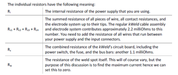
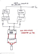
Make sure "all combined" red wires length in your set-up are not exceeding 1m altogether.


See pictures, they are from kWeld's manual.

Some people overlooked this basic and damaged their kWeld - it is painful. :cry: :cry:


442B.png


443.png


400386.jpg


Sorry for my handwriting & sketches if they are hard to read.
 
** Precautions ** :warn: :warn:

Connecting batt (or PSU) directly to large capacitor is dangerous, especially SuperCaps, they have very low impedance when empty or almost empty. The high inrush current can destroy the caps and/or your batt (or PSU). It is like shorting circuit intentionally. You will need current limiting device (i.e. CC-CV, etc.) for this. Programmable CC-CV is one of the ideal choice for kCap. Such CC-CV device will start feeding current (lower V) to kCap at a preset rate (mine set at 14-15A each, 2sets in parallel), then when the caps are at the last ≈5-10% full, CC-CV will charge with fix V mode slowly, until reaching its preset V. Charging SuperCap is supposed to be this way.

Programmability CC-CV will be quite useful to fine tune Vcap, resulting in reliable high current for every charging after each weld. Only problem with my system is at the top few % charging, it will be slow (20+sec between welds). Since it is CC-CV, charging from 8.20 to 8.45V is only 0.25V diff, charging current is limited to tens of milliamps - that's why it is slow at the top.

It is also dangerous to connect multiple capacitors (>1) in series without balancing board. :warn: :warn: Like using a lithium batt pack without a BMS. Similarly, capacitors are not identical even labelled as such. So a little variation can cause unbalanced voltage divider among the caps and some will reach / exceed Vmax sooner. You do not want to witness over-charged SuperCaps or lithium cells !! :warn: :warn:

Do use reliable balancing board for your caps in series. kCap is already equipped with balancing board from factory. :) :)

+ Tidy up your work space when working. Batt pack under welding process has infinite numbers of exposed ready-to-spark spots. Cover work pieces with insulator, just open only the small part we need to work on. Once a probe touches with any open pads it can create a huge short and sending very high current back into kWeld and it's fried. Lots of hassles and headache.

+ If magnet is used to hold nickel / insulator to cells' tops, make sure you tape it before use. It can short circuit ! Cannot emphasize enough. Been there, done that.

+ Do not exceed 1-m total conductor length. No-go zone.


397922_0.jpg
 
My original set-up :

+ I use kWeld + kCAP 2018 version. I feed the kCAP with 2 parallel 12V 30A simple PSUs via programmable CC-CV regulators and power diodes in series. I prefer a plug-in system than battery-operated since it is all-in-1 and can work continuously without running out of juice. Simple, robust, compact, light, easy, fine-tunable, and long life cycle (kWeld's Maxwell 310F 2.7V, ≈500k life cycles). I am not sure whether there is anything that can outperform it in all these aspects. Not batteries, not MOT, etc. The alternative, batts with high CCA are heavy, bulky, expensive, and need big charger. My system runs well so far. If you have either one around (PSUs or heavy batt), just use it. If not, choose whatever you like.

In case you have big batt (or big PSU) and you also like to use kCap, a current limiter like CC-CV is recommended.

+ Original kWeld welding cables are 8AWG with total length of about 40cm each side (same red color). Making total conductor length not exceeding 1m - safe zone.


400408.jpg
 
My kWeld mods :

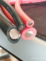
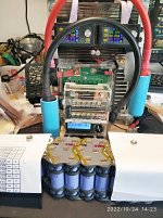
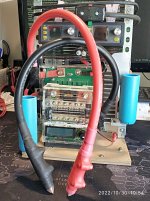
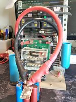
The straightforward approach is to reduce R from conductors like cables. The bigger, the better but not too difficult to handle. I chose 2AWG, same length with the original 8AWG. R will drop to about 1/4 of factory cables thus will boost up current. Watch the curvature of the 2AWG. My attached VDO clip show how I did it and just go with the 2AWG natural bend, it will not be difficult to handle despite the 4X bigger cross-sectional area. 2AWG * 40-cm long each side is easier to handle than it sounds, as long as you go with the natural bend of the big cable.

+ Cable : Frank always emphasizes about not to exceed 1-m overall conductor length excluding probes. That will make the welding cable only 40-cm each side. Exceeding that will cause higher inductance L and higher kickback energy that can severely damage kWeld. For both batt and kCap cables, 2 constraints involved, R (copper loss : the lower the better = higher amps) and L (intrinsic inductance - this one cause major backfire of energy to kWeld and can damage it.) As real mishaps also occurred with some members as we read through the threads on ES.

My very first mod with cable was using another 8AWG (≈8.37mm2) parallel to the original ones = 2*8AWG (≈16.74mm2). It did boost up current to about 14xx-15xx amps at 130-140J but still not enough to weld 0.2mm Cu + 0.15Ni(Fe) reliably. So I went further to 2AWG (≈33mm2). Quick ref : 8AWG=8.37mm2 / 6AWG=13.3mm2 / 4AWG=21.2mm2 / 2AWG=33.6mm2 / 1AWG=42.4mm2 / 0AWG=53.5mm2 / 00AWG=67.4mm2


398260.jpg


397924_0.jpg


398235.jpg


398232.jpg


398246.jpg
 
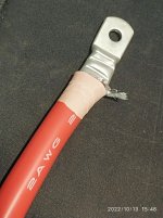
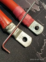
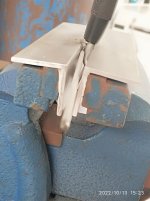
+ Lug terminals: AWG lugs are a bit hard to find in my local stores. So I use 35sq.mm, with ∅6-mm hole to crimp this 2AWG. A bit too small, so I can only fit 90+% of the fine Cu strands into the lug. The remaining strands was wrapped outside. I do not have crimping tool for this size of lug & cable. So, I improvised by using shop vise to clamp those lugs with the help of ≈∅2mm L-wrench to create 2 cross deep dents into each lug ensuing tight grips and very good electrical contact. Result was effective - cannot physically pull cable out manually. NEVER solder your lugs and Cu, they must directly touch metal-to-metal with as large contact area as possible. We are working at sub-milli-Ohm here. Tin & lead are poor conductors in high current applications despite they look very promising. Soldering is for small gauge wires only where hundreds milli-Ohms is still acceptable.

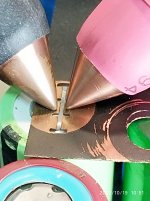
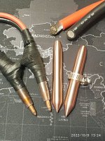
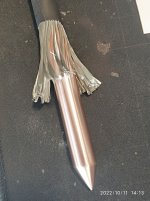
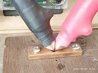
+ Probes (electrodes) : I can only find EK2 copper rod in my local stores. It is normally used for shop metal-sheet spot-welders' electrodes. So I bought a 1-m * ∅12.5mm (1/2") rod which has about 90% more sectional area than kWeld 's ∅9-mm probes. But after tested, it was not as hard/durable as the C14500 Tellurium copper on kWeld. Every 40-50 welds, this EK2 becomes too dull and rounded causing big welded spots (but welds stick well enough). Not to mention the red hot tips after every weld, that always oxidise and weakened the tips easily. So, re-sharpens are needed oftenly. Cleanliness of tips play a big role to weld quality. Do have some brass brush around and wipe tips before & after every weld. With this EK2 Cu, welding quality is OK with a bit of stickiness at the beginning few welds. Need C14500 Tellurium Cu (like kWeld) to replace this too soft EK2 . Just ordered from AliExpress, 2pcs of Æ12mm*L100mm C14500 Tellurium Cu rods cost me $25.- not cheap though.

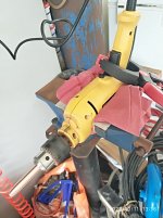
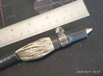
I DIYed these EK2 Cu probes quick & easy. By using hand drill, coarse file and 800-grit sand papers to lathe/sand Cu rod into shape, results is good enough. SUS 304 hose clamps were used to tightly wrap 2AWG conductor (spread evenly) to these Cu probes, providing plenty of contact surface (at least L25mm * ∅12.5mm ≈ 1,000mm2 ) for very high current. The 2 clamps on each probe also act as a grip handle for prolong use. Then shrink-tubed them several layers. I also use Red-Black colors for the 2AWG cable to differentiate the + and + leads. Also found out that the - spots tends to stick better, so I kept switching welding sides to ensure consistency of welds. Just try to minimize any possible errors.


398249.jpg


400063.jpg


398250.jpg


394674.jpg


398255.jpg


398256.jpg


398257.jpg
 
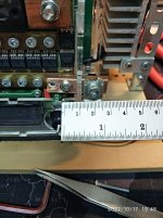
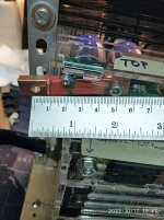
+ Bus bar & fuse : The original position & space for 8AWG on kWeld is OK but not for 2AWG. So I extended a T6*W12*L50mm (72mm2 that was what I had) Cu busbar from original kCap + terminal outside, to fed to kWeld pcb. Similar with the - welding cable (black), I used a T6*W12*L20mm (72mm2) Cu busbar. More than enough for both high current and mechanical strength to hold the heavy 2AWG.

Frank mentioned that the big fuse was intended for battery-operated kWeld. SuperCap units can omit this fuse since 3S2P caps module store not much energy to cause big damages. But the kWeld circuit needs power through that fuse. So the old 8AWG * L10-cm through the fuse to power the circuit is still needed.

+ DO NOT alter the factory top & bottom brass busbars at MOSFET switches. Since it also works as current sensing feedback. Frank replied : "Modifying it will mess up this important function" to my question asking to change those brass to Cu.

+ TVS diode : For each weld, high current will flow through the intended spots. When switch off, inductance L in the circuit will try to maintain this energy and it must go somewhere. This TVS diode is for this purpose. We should not exceed the 1-m total conductors length to ensure not too high energy kickback will go to damage the circuit.

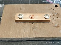
+ "CAL" "SHORT!" test jig. kWeld requires the user to measurethe "as-is" system R that the user will have to push the 2 probes together firmly, and that is not easy. I had to do that many times with vise-grip clamping them, especially for smaller probes, or we don't get accurate R. This jig can help. It is just a small bore drilled Cu bar just enough to push both probes in firmly.

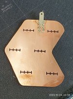
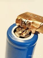
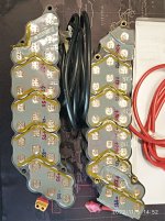
+ Cu & Ni(Fe) : Strips are OK but why settle for just OK when we can do much better. So I chose the cut-to-shape pads (laser-ed) 0.2mm Cu, and bought 0.15mm Ni(Fe) tabs. Slit cuts on Cu & Ni(Fe) also prevent welding current to shortcut via Cu or Ni(Fe) but to go deeper through cell cap. This Ni(Fe) tab is just for heating up Cu & Cell cap underneath to their melting point. We want this Ni(Fe) to get very very hot and long enough to melt Cu, so, pure Ni will not heat up as much (due to lower R). Then I just cut these Ni(Fe) into small tabs, enough to weld 3-4 times. I posted some pics here : ( https://www.endless-sphere.com/forums/viewtopic.php?f=14&t=117491&p=1730424&hilit=ichiban#p1730056 ) . I also painted the Cu pads hoping to insulate the thing, but the paint job was so poor. Need better paint (or better me) next time.


398247.jpg


398248.jpg


400070.jpg


398225_0.jpg


398226.jpg
 
Settings :

First time powering kWeld on, or altering its R or changing power source somehow, we have to do calibration "CAL" in the menu. Do read the kWeld manual and just follow the steps.

+ For calibration, kWeld needs to know/memorize "as-is" overall R of the system (without Ni/Cu/cells) to calculate & compensate for actual welding parameters. This is done during calibration "CAL" "SHORT!" that probes are required to be firmly pressed together. Current will be higher than actual welds (with additional Cu, Ni and Cell cap), up to an error "Overcurrent" (spec 2000A max by default) might be displayed. Should this error occur, kWeld will not recognize this value, and we will need to do "CAL" "SHORT!" again until no error. To fix "Overcurrent" during "SHORT!", we need to lower Vcap. kCap's 3S2P Maxwell 310F each cap spec 2.7V nominal / 2.85V absolute max, so 8.2V should be mid value, and 8.55V is absolute max for the whole module. Here comes the gimmick of the programmable features, my CC-CV programmable regulator can adjust this V, so I gradually lowered this V and "CAL" "SHORT!" until no more "Overcurrent". This is the highest Vcap closest to 2000-A kWeld limit and not getting "Overcurrent". My highest Vcap for "CAL" "SHORT!" is 8.25V to reach 1,9xx A. When a bit more at 8.15V. got me an "OverCurrent" error. You need to find your own max Vcap for "CAL" "SHORT!", each kWeld might be different, especially after you made some mods to it.
 
+ For actual welds :

+ kCap's 3S2P module can be charged up to 8.55V absolute max. Do provide some safety margin, like 8.45V at the highest. Less amps = slower charging and wait time between welds. I set my system to feed 14A*2 = 28A CC at start. CC-CV charger works well to start filling the caps quickly to almost full, then slows down considerably before filling up. I will wait until charging is below 100mA and less than 1watt to reach preset Vcap of ≈8.45V. Then I will proceed to the next weld.

+ Cu + Ni + Cell cap are added into the loop which increase R and decrease amps. So we will need to increase Vcap a bit more, but NOT exceeding our Vcap absolute max of 8.55V. I set mine at 8.45V but I think it is too close to Vcap-max at 8.55V, 8.40V max should be better. My actual welds with this 8.45Vcap can achieve 1,7xx-1,800 A and a bit higher. Too close to this value (8.55V) is too risky, exceeding it is looking for fireworks. Be safe.

+ Normal R for "SHORT!" should be within 2.5-3mOhm with stock 8AWG cables. After my above mods, R dropped to 0.6-0.8mOhm given clean probes and with the help of "SHORT!" adaptor if it is too hard to push manually. It is just a small Cu bar (with pre-drilled hole on a base) enabling you to push both probes down touching each other very firmly with full force. This will get us very close to actual system R.
 
Welding :

+ Make sure Vcap reaches the desire 8.40-8.45V before welding, in order to get the max current and really good welds.

+ Perform squishing (wiggling) of both probes (back & forth with pressure down) on top of Ni(Fe) + Cu + cell cap several times while pushing hard & hold probes still before triggering weld to ensure very good electrical contact. Good welding quality depends heavily on this.

+ Read the result of welding parameters shown on display. Current should be as high as possible, Time should be low, R should be low, Temp should not exceed room temp by much. Consistency of these parameters from weld to weld is a must.

+ For examples, my average readings : @140J, I =1750+A, T= 75mS, R=0.65mOhm, temp=38C

+ I live in hot & humid tropical area where my garage lab is also open-aired. It is quite normal that humidity exceed 70-80%. Refrigerating the cell pack before welding is not a good option for me. It will attract condensation and wet the cells when welding. I assume that refrigeration might cool the cells down to -10C , but welding spots temp can easily exceeding 1,000C to fuse Cu/Ni. Plus, spot-welding is supposed to heat up only the surface or shallow distance from surface. So, the pre-cooling does not do much good for me.
 
Results :

+ After above mods, kWeld can achieve 1,7xx-1,8xx A at 140J, 70-80 mSec and 0.6x-0.8x mOhm for actual welds on 0.15mm Ni-plated steel + 0.2mm Cu, both slotted, at Vcap 8.40-8.45V. I have repeatedly welded actual batt pack for 200+welds with good results at 140J. Actually, it can stick even at 110J/120J setting and above, but I just want a fool-proof quality for each weld. Spot-welding is a one-time thing without an easy way to check results without ripping off the pieces. We have to trust it. All welds are supposed to last longer than the batt pack itself, practically forever.


400066.jpg


400060.jpg


400055.jpg


400081.jpg


I forgot how to attach video file mp4.
 
Some useful ref :
+ Spinningmagnets recommended a "tip-toe" technique - worth trying :
Re: kWeld - "Next level" DIY battery spot welder
by spinningmagnets » Mar 17 2021 9:56pm

***Re: DIY Arduino timed spot-welder, FET-switched, adj. pulse***
by myxomop » Oct 17 2021 3:53pm
Malectrics V4, super capacitors 3000F 2.8V ESR 0.2mOhm
Shunt 1500A 75mV 0.5% 3800A Tektronix shows even a little more

Re: kWeld - "Next level" DIY battery spot welder
by nuxland » Dec 18 2021 4:16pm
*** 0,2mm nikkel to 0,5mm copper ***
one electrod was in copper side and other in nikkel side.
 
When we connect capacitors in series, overall capacitance will be reduces by C-all = [ C1+C2+C3+… +Cn ] / n, if they all are of same value (F). kCap also follows this rule, Maxwell 3S2P of 310F 2.7Vnom & 2.85Vmax results in total 206F / 8.1Vnom & 8.55Vmax. Its' total ESR ≈ (2.2mΩ*3)/2 = 3.3mΩ. Assume 8Vcap + MosFet IR + R-load ≈ 8V / (3.3mΩ + 1mΩ), so what we can get max current out of this set-up is ≈ 1,7xx-1,8xx amps.

If still not satisfied yet, read on.
 
Frank mentioned 4S2P Caps somewhere, with Balance board. Might need to change power supplies to accommodate 2.85Vcap-max * 4S = 11.4V + Vregulator + Vdiodes (in my case).

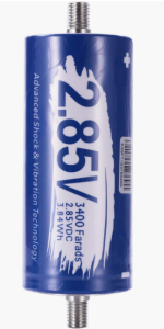
I also came across Maxwell 3.0V/3.15Vmax 3400F SuperCap. 10X the capacity, 10x lower ESR, higher Vcap & super high short cct current (20kA), 1M cycles, etc. Need to find the right balance board, 4S2P sounds interesting. May be we can weld thicker Cu directly to cell cap with its hard-core specs :

https://www.aliexpress.com/item/1005004899082543.html?spm=a2g0o.cart.0.0.390c38daYjf6lQ&mp=1

With these 3xxxF caps, lowering ESR from 2-3mΩ (kWeld original 310F 3S2P) to 0.2-0.3mΩ is a huge leap. Where we can hardly cut down any significant R value from wires since 2AWG is already very big and shorter wires will be difficult to work with. So this 3,xxxF caps are very very interesting.


441.png


View attachment Maxwell BCAP310+350F2.7V.pdf


View attachment Maxwell 3V_3400F_BCAP3400 P300 K04_05.pdf
 
Should we build SuperCap module out of this Maxwell 3400F, 3V/3.15Vmax. For 3S2P, we will get 2,266F with higher Vcap, much lower ESR, 10x the Farad, I expect > 3,xxx Amp output can be achieved. Or the more hard-core 4S2P, or even 4S1P with the > 3,xxxF, 2.85V (total 750F or so) this is what we can get much more headroom V (2.85V*4Serial). From V = I*R, increase V (from 3S to 4S caps = from 8.55Vmax to 11.4Vmax) and lower R (big wires), Imax will be increased and t will be decreased dramatically - that is exactly what we want for high Q (very high energy in very short time). PSU might need to be upgraded to ≈14.5V / > 60A, programmable CC-CV charger preferred. Just make sure your gears can withstand this magnitude of punch. The 3S/4S balancer board also needed. Should be able to weld thicker Cu directly to cell cap. May be 0.3-0.5mm ? Have to unlock current kWeld from its 2,000-A limit (factory default). It just looks promising. These Maxwell 3400F3V/3.15Vmax are expensive plus they are heavy and gigantic (1 pc ≈ 1 soda can). So shipping cost will be steep too. Alternatively, I found 3400F 2.85V Maxwell used ones for sales cheap at $10.- ea. But buying used ones is like buying lotto, could be a complete Crapacitor. :lol: :lol: The ESR is what matters here and they keep increasing with usage - not to mention if they are even genuine Maxwell originally. That's the trade-off. I don't know whether there is an easy way to test these SuperCaps reliably, especially the ESR. Any idea ?

Also the TVS diodes might need mods to cope with the new much higher oomphs ?

Frank, do these sound OK to you ? Is it possible to unlock this kWeld's 2,000-A limit ? Pls advise. :) :)
 
Hope my shared info here help to clarify your questions re how to reliably weld 0.15mm Ni(Fe) + 0.2mm Cu or thicker using current model kWeld (upto 2022.10 version, mine was circa 2018). Be very careful when you mod something. Make sure you really know what you are doing / or ask questions here. Safety first. I tried to post pictures of my mods believing it helps you guys to see the details. Have fun and be safe ! :) :) :)
 
I forgot how to attach MP4 video clip. Cannot find instructions anywhere. It would be easier/clearer for some demo. Someone pls tell me how to. Thanks. :) :)
 
Back
Top