
You are using an out of date browser. It may not display this or other websites correctly.
You should upgrade or use an alternative browser.
You should upgrade or use an alternative browser.
Active pre-charge/inrush control
- Thread starter boo
- Start date
is it possible to use the existing design with such a mosfet?
or this one
 www.distrelec.at
or this one
MMIX1F520N075T2 | Ixys MOSFET, N-Kanal, 75V, 500A, SMPD | Distrelec Österreich
Kaufen Sie MOSFET, N-Kanal, 75V, 500A, SMPD. Entdecken Sie unsere aktuellen Angebote zu Transistoren - MOSFETs. Lieferung am nächsten Tag möglich.
Either of those would work but possibly overkill. What voltage/current is your controller rated for?
I think the best design will be a two stage switch with a pre-charge resistor on the first stage. Each switch then turns on as fast as possible. The second (main) FET switches on after the pre-charge is complete. This should eliminate things blowing up and can handle some amount of standby current. I don't have this design worked out yet, but there are several ways it could be done.
I think the best design will be a two stage switch with a pre-charge resistor on the first stage. Each switch then turns on as fast as possible. The second (main) FET switches on after the pre-charge is complete. This should eliminate things blowing up and can handle some amount of standby current. I don't have this design worked out yet, but there are several ways it could be done.
Powervelocity.com
100 kW
I've been using a modified version of the design with the added auxiliary turn-off circuit, TVS, and the capacitor from gate to source rather than the drain. It has worked fine overall even above 100v. One minor issue is that mosfets in the off state prevent the current flow from the battery to the controller but the body diodes will allow current flow from the controller to the battery regardless. This would be a concern when a disconnect is needed when a motor is running and regenerating.
Can you post a schematic of that one? I know you blew up some parts making something that worked.
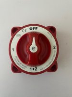
That should work great, but it's a bit large. Where did you find that switch?
Powervelocity.com
100 kW
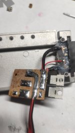
This is the design adopted for the PV-nextGen controllers, three 210A 150v rated mosfets are used for the contactor/pre-charge, and they are mounted on the power stage IMS board sharing the heatsink with the phase switches.
The zener closest to the mosfet is a TVS to protect it from the voltage spikes that transpire more with higher voltage (above 70v or so). The transitor/diode circuit is designed to speed up 10uF cap discharge (gate turn off) and not allow the gate voltage to dwell in the linear region uncontrollably. It's probably not ideal but this is what has worked after burning through a lot of mosfets. Any suggestions how to make it to more reliable would be greatly appreciated. I am thinking an comparator solution would be more robust - basically turning on the mosfets fast only when a pre-charge voltage threshold is reached and avoid using mosfets for precharge altogether.

The zener closest to the mosfet is a TVS to protect it from the voltage spikes that transpire more with higher voltage (above 70v or so). The transitor/diode circuit is designed to speed up 10uF cap discharge (gate turn off) and not allow the gate voltage to dwell in the linear region uncontrollably. It's probably not ideal but this is what has worked after burning through a lot of mosfets. Any suggestions how to make it to more reliable would be greatly appreciated. I am thinking an comparator solution would be more robust - basically turning on the mosfets fast only when a pre-charge voltage threshold is reached and avoid using mosfets for precharge altogether.
Can you post a schematic of that one? I know you blew up some parts making something that worked.
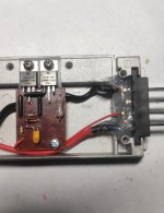
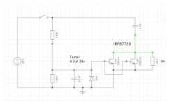
I made this circuit for myself, based on the Pryside circuit .
That's nice. The precharging is done by the resistor, which should keep the FETs from blowing up. I like it.
I use with a 48V 13A controller. I think that recuperation will work, since the transistor will conduct current in the open state in both directions.nice, what current are you using it with cont.? And can this recuperate?

That's the controller cap(s).
Yes, it will work with regen no problem.
Powervelocity.com
100 kW
The regen will work simply because body diodes in mosfets are conducting in reverse regardless whether the mosfets are on or off. This is kind of downside compared to a contactor that turns off the current flow in both directions. Most BMSes use mosfets in series to deal with that issue but of course that doubles the mosfet resistance.
Regarding the schematics above, placing the switch in that location certainly works for 13A but would be problematic with 100A or 300A. Basically, a properly rated contactor would be needed at that point which kind of defeats the purpose of the original design.
Regarding the schematics above, placing the switch in that location certainly works for 13A but would be problematic with 100A or 300A. Basically, a properly rated contactor would be needed at that point which kind of defeats the purpose of the original design.
The Pryside circuit might be great for those applications where you unplug the pack every time and don't use a switch. You would get a small spark on connecting, but not enough to damage the connectors.
But another way to do it would be to only switch the precharge resistor and control circuit. Below is one way to do that.
If you had (just an example) 100V and used a 10 ohm precharge resistor, current through the switch would be 10A maximum, and generally near zero. This way you could use a more reasonable switch size and wire to the switch. Switch off grounds the gates and will turn of very fast. There will still be 100uA of drain from the 1M resistor. Not enough to worry about in most cases. For long term storage, unplug the battery.
The idea is the precharge resistor will fully precharge the controller caps before the FETs turn on. There will be a little voltage across it due the standby drain of the controller, but it should be minimal.
In stead of using a 10 ohm resistor, you could also use a PTC. Something like DigiKey Part Number TRF600-150-RB-ND $1.27ea.
This starts out around 9 ohms and will stay that way for a normal precharge. IF the controller was shorted, the PTC would trip and prevent any fires and automatically reset when the short was removed. They are about as cheap as a resistor, so why not?
Last edited:
The reason many of these designs have had failures is they put the FETs outside the safe operating area. Below is a typical graph for my favorite IRFB4110 part:

For a slow turn-on, you might be closer to the "DC" line, where things blow up pretty easily. The solution is to try to keep things in the safe area. If you had a proper gate driver that could turn the FETs on really quickly, you might be able to just slam the thing on without blowing things up.

Above is a new design that tries to keep the FETs in the safe operating area and allows using a very small SPST switch to turn things on/off. You could also leave the switch permanently on if you typically unplug the battery every time. Essentially zero current drain when turned off.
When the switch is turned on, Q1 turns on fast and precharges the controller via R3. R3 needs to be pretty big, but only dissipates heat during a brief period.
Q2 and Q3 keep the main FET gates pulled down until the precharge gets to within about 5v of the pack voltage, then allows them to turn on. If the precharge resistor burns out or the controller is shorted, Q3 prevents the main FETs from turning on. If there is only about 5v across the FETs, they should be in the safe area even when turning on slow. Q2 and Q3 can be any small NPN transistor with adequate voltage rating.
Q4-Q6 can have more parallel parts added to for increased current capacity.
D1 ensures Q3 stays off when the output is on. C1 prevents the main FETs from turning on during initial startup until Q3 turns on. D1 can be something like a 1N4004.
Well, this design is NOT tested yet, so there could be issues, but I think this will work. I have another design that uses a UCC27524 gate driver chip, but then you need a voltage regulator and things start getting more complex/expensive.
For a slow turn-on, you might be closer to the "DC" line, where things blow up pretty easily. The solution is to try to keep things in the safe area. If you had a proper gate driver that could turn the FETs on really quickly, you might be able to just slam the thing on without blowing things up.
Above is a new design that tries to keep the FETs in the safe operating area and allows using a very small SPST switch to turn things on/off. You could also leave the switch permanently on if you typically unplug the battery every time. Essentially zero current drain when turned off.
When the switch is turned on, Q1 turns on fast and precharges the controller via R3. R3 needs to be pretty big, but only dissipates heat during a brief period.
Q2 and Q3 keep the main FET gates pulled down until the precharge gets to within about 5v of the pack voltage, then allows them to turn on. If the precharge resistor burns out or the controller is shorted, Q3 prevents the main FETs from turning on. If there is only about 5v across the FETs, they should be in the safe area even when turning on slow. Q2 and Q3 can be any small NPN transistor with adequate voltage rating.
Q4-Q6 can have more parallel parts added to for increased current capacity.
D1 ensures Q3 stays off when the output is on. C1 prevents the main FETs from turning on during initial startup until Q3 turns on. D1 can be something like a 1N4004.
Well, this design is NOT tested yet, so there could be issues, but I think this will work. I have another design that uses a UCC27524 gate driver chip, but then you need a voltage regulator and things start getting more complex/expensive.
Not wanting to hijack a thread on an analog solution, but this is the kind of thing small micro controllers excel at.
The main switch powers up the micro via a resistor+zener reg, It turns on the FET with the precharge resistor (or better yet, PWM's it and uses and inductor) . Whilst its doing this, it monitors the controller voltage and turns on the main FETS when a threshold is reached.
The main switch powers up the micro via a resistor+zener reg, It turns on the FET with the precharge resistor (or better yet, PWM's it and uses and inductor) . Whilst its doing this, it monitors the controller voltage and turns on the main FETS when a threshold is reached.
I have nothing against something like an Arduino. I got some Nanos for about $5 each. The biggest issue is supplying the 5v. Depending on the power consumption, a linear regulator is likely to get hot.
You could do it with an arduino i guess. You can put them into very low power modes, like way less than 1mA, this resolves dissipation.I have nothing against something like an Arduino. I got some Nanos for about $5 each. The biggest issue is supplying the 5v. Depending on the power consumption, a linear regulator is likely to get hot.
eg 48V-5V=43V @ 0.001A = 0.043W.
With an Arduino, you could easily implement all kinds of fancy features, like safety lockouts and automatic shut off if the battery isn't being used for some amount of time. A simple transistor/zener linear regulator would probably work but you would want to drive the FET gates with at least 10v while the processor needs 5v or 3.3v. I'll have to look into that.
Some members posting to my old Nano Tidbits thread suggested some ways to get the 5v from battery voltage; I don't recall what they were but should be here:

 endless-sphere.com
Arduino Nano Cycle Analyst (and other) companion TidBits
Ok, so I finally went digital, and got a set of three (so blowing one up wont' delay me much) Arduino Nanos here: https://www.amazon.com/gp/product/B01DLIJQA2?psc=1 (because it was fast and convenient and others here bought other things successfully from them), and have officially started...
According to the datasheet for the Nano versions I have, the onboard regulator can handle 5-20v input. So a 12v supply could run the Nano and drive the gates.

Back on the analog front, I figured out I didn't need Q2 and just the diode will take care of turning off Q3.
The R5/R6 divider controls the point at which Q3 turns off and allows the main FETs to turn on. Roughly 5v with the shown values.

Back on the analog front, I figured out I didn't need Q2 and just the diode will take care of turning off Q3.
The R5/R6 divider controls the point at which Q3 turns off and allows the main FETs to turn on. Roughly 5v with the shown values.
Similar threads

- Replies
- 5
- Views
- 852
- Replies
- 4
- Views
- 688
- Replies
- 3
- Views
- 832
- Replies
- 1
- Views
- 1,597