A123 20AHr Pouch Cell Battery Build & Info Thread

dnmun said:
it was my fault for mentioning the idea of a brass split pin, cotter key. i was thinking of the difficulty soldering to the steel, and was thinking brass would make it easier. i had totally missed how ebv rolled this and clamped it in the vise and put the washer on it when i first saw the pictures. now i like JD's idea about using a spot welder first and rolling it up after. just am thinking of the sense wire all the time.

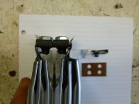
I was able to roll the balance wire into the crimp, although it was a challenge, and thicker strands worked better than fine strands. Since the balance wire only sees a handful of amps instead of 100's, it needs very little contact area, and the risk from doing it badly is having resistance cause an inefficient balance charge (not regular bulk charges) for that cell, very little wasted current.

-JD
 
oatnet said:
Luke, you always seem to see an angle I miss, but I don't understand this issue. Since this pin is external to the interface between the tabs, isolated from the pack and outside air with heatshrink, what is the risk here?

-JD


A steel cotter pin has the resistance of something like a 18awg copper wire. If you conduct through the pin, it's going to be hot in a second, and release it's clamp load. The clamp load is what provides all the desired electrical connection.
 
liveforphysics said:
oatnet said:
Luke, you always seem to see an angle I miss, but I don't understand this issue. Since this pin is external to the interface between the tabs, isolated from the pack and outside air with heatshrink, what is the risk here?

-JD


A steel cotter pin has the resistance of something like a 18awg copper wire. If you conduct through the pin, it's going to be hot in a second, and release it's clamp load. The clamp load is what provides all the desired electrical connection.

OK, I see where you are going, thanks Luke!

I think in this application the welded tabs will be inside the cotter pin, so while it is part of the conductive package, there is a huge low-resistance pathway through the welded tabs, so it does not carry the load. If the tabs are rolled up and crimped, then the entire surface on both sides of each tab make a low resistance pathway, so it won't matter if there is a steel cotter in the middle.

I'm going to try this on my next 1p pack-build, a cotter pin should be much easier to work with than clamps. :D :D :D EVB thanks for the cotter pin idea, and Dnmum thanks for the idea of spot-welding the cotter pin.

-JD
 
oatnet said:
liveforphysics said:
oatnet said:
Luke, you always seem to see an angle I miss, but I don't understand this issue. Since this pin is external to the interface between the tabs, isolated from the pack and outside air with heatshrink, what is the risk here?

-JD


A steel cotter pin has the resistance of something like a 18awg copper wire. If you conduct through the pin, it's going to be hot in a second, and release it's clamp load. The clamp load is what provides all the desired electrical connection.

OK, I see where you are going, thanks Luke!

I think in this application the welded tabs will be inside the cotter pin, so while it is part of the conductive package, there is a huge low-resistance pathway through the welded tabs, so it does not carry the load. If the tabs are rolled up and crimped, then the entire surface on both sides of each tab make a low resistance pathway, so it won't matter if there is a steel cotter in the middle.

I'm going to try this on my next 1p pack-build, a cotter pin should be much easier to work with than clamps. :D :D :D EVB thanks for the cotter pin idea, and Dnmum thanks for the idea of spot-welding the cotter pin.

-JD
So what tool are you using to crimp the tabs?
 
Those are mine, more description on this build thread:
http://endless-sphere.com/forums/viewtopic.php?f=6&t=12461&start=60#p281360

I used a set of wide-jawed vice grips to hold the tabs together, as well as the straight edge for the first bend in the tab. It usually took me a couple of trys to get everything lined up just so, but it was nice to be able to release the clamp and do-over, because the first bend dicatates how the rest of the roll will go.

Once I had the bend as far as the Vice-Grips can go before interfering, I used a pair of large electrician's pliers to crimp it down. The pattern in the jaws formed indentations that really lock the tabs together, stretching the metal and expanding the contact surface even further. That first fold was always tough, because the tabs can still move around, and the balance wire wants to pop out.

I think I used my hands to roll the soft tabs together, and crimped with the same pliers after each fold. The indentations also are what made it hard for me to seperate the tabs later.

-JD
 
So last night made a 12s pack using drutledge's method of compression of the tabs.

Got my cell_man 12s 80amp BMS and am about to put it on the pack.. had a question and I know this is BMS related , but
it's in regard to my build. I have never used a BMS before and the diagram makes what goes where pretty obvious.

One question I have is how much current can I send into the charge plug ?

I charge with 2 modded 12V HP supplies into a icharger 306b on my lipo currently.

Thanks - looked around , but did not find any obvious answers must be buried or I am blind.
 
i was thinking about that. watching evb's fold and crimp and then JD's idea to spot weld the split pin at the top of the tab and then roll it down.

i wonder if it is really best to fold and roll the tabs, instead have the tabs stick up through some kinda top plate, above the pouches, and then the tabs would be up on top, clamp with the split pin, spot weld with the sense wire attached, then cap the tab/split pin with a shrink top, and then glue that shrunk top into the plate above the cells so the weight of the attachment area, where the tabs and split pin hang at the top would be supported and physically restrained from vibrating. that would leave all the connections on top where they could be probed with the voltmeter.

i learned from examining the ping packs that the tab breaks at the spot where he folds the tab back over the end of the mylar as it exits the pouch, where the tab actually is bent 180o in a very tight fold over the edge of the mylar. this spot is stressed from the the folding, and the strain causes voids in the aluminum which then is further eroded by the electromigration of the remaining aluminum out of the remaining metal left continuous in that fold. eventually it just separates, like a sheet of paper folded along a dotted line, with the perforations of the paper being the equivalent of the strained aluminum crystals.
 
Why not leave a little bit of tab under the fiber board or not pull it to tight. I think Ping leaves a small crease. As not to pull the tabs out the top. Could you just solder on the sense wire to the copper tap in a 1s pack except the pos. end.


Edit: In a 1p pack you could solder to the cooper tap ? And for the aliumun pos. end tab you can solder to the 8 ga. copper pos. wire.
 
dnmun said:
maybe someone will try using these spit pins and then use the spot welder on them with the tabs in the middle of the split pin.

soldering to steel is hard, maybe there is some way to pretin that spot and solder in the sense wire before assembling.

really neat and simple idea though.

As promised, I tried this on my next pack build. It rocks, great idea, it is much much faster than my previous steel-strip method, and I will be using it going forward. I documented the process and added it to my a123 spot welding thread here:

http://endless-sphere.com/forums/viewtopic.php?f=14&t=29959&p=588583#p588583

Oh, and in the post right before that one, I cut open an old dead 20ah a123 prisimatic cell, and took pictures of the guts. :twisted:

-JD

 
dnmun said:
this split pin approach was a great idea that started with evb on the other thread, i just think out loud, but this is so simple now, reliable connections, easy to go back and replace defective cells.

Oatnet, JD, thanks for the excellent documentation. Everyone should follow your example of providing such detailed photos & info. :D

A few questions:

1) So, once you've welded the tabs is there still plenty of space left to cut this welded section off to do a repair by replacing one of the welded cells with a new cell? If yes, then will you be able to undo & unfold everything reusing the one good cell that you had to cut its welded section off of too?

2) What is the dimension of just the tab area that can be worked on or folded that sticks up?

3) Can you work safely right down to the edge of the cell where the tab begins to stick out, or what would be the "safety gap" or space buffer to use?

4) What is the minimum cost for a spot welder to do this specific job as good as your spot welder can do this now? Recommendations?

5) How are you sanding & prepping the tabs to remove the protective film surface coating?
 
deVries said:
dnmun said:
this split pin approach was a great idea that started with evb on the other thread, i just think out loud, but this is so simple now, reliable connections, easy to go back and replace defective cells.

Oatnet, JD, thanks for the excellent documentation. Everyone should follow your example of providing such detailed photos & info. :D

A few questions:

1) So, once you've welded the tabs is there still plenty of space left to cut this welded section off to do a repair by replacing one of the welded cells with a new cell? If yes, then will you be able to undo & unfold everything reusing the one good cell that you had to cut its welded section off of too?

2) What is the dimension of just the tab area that can be worked on or folded that sticks up?

3) Can you work safely right down to the edge of the cell where the tab begins to stick out, or what would be the "safety gap" or space buffer to use?

4) What is the minimum cost for a spot welder to do this specific job as good as your spot welder can do this now? Recommendations?

5) How are you sanding & prepping the tabs to remove the protective film surface coating?


Thanks DeVries! I think if you read my earlier posts in the spot-welding thread it will fill in the gaps, but here are answers:

1) Yes, every single one of my crimp and spot welds since 2010 have been reversible. It takes time and patience to unfold, but I have done it. With spot welding, you have to cut off the welded section; with cotter pins, that section is smaller.

2) the part you see, I've never found a need to measure it, nor could I use this measurements in practice. Each roll is different, depending how you placed you cotter pin, how tight you fold it etc. There are pictures from multiple posts showing diffferent techniques to give you an idea.

3) I use a safety gap that will let me get heat shrink under the roll, I eyeball the distance.

4) Quote on Spot welder selection: "This is Harbor Freights $160 "115v spot-welder" I could have purchased the same product on ebay for $35 less, but I wanted to be able to return it." Now that I know it works, I would have saved money and purchased the identical eBay version.

5) not aware of any protective coating, just oxidation, which I would recommended buffing out to your preferences.
 
Hi JD,

I just wanted to get your answers into this thread too, beyond your thread topic, since it will cover here the various methods to assemble cells into a battery.

For those of us that don't have our cells yet, when you have time, could you please measure the L x W dimensional area of just the tab area that sticks up? This will give us an idea how much tab we have available to work with.

Thanks! :D
 
You see any of those 35$ welders now ? looking at ebay 136.99 is the lowest I found.

Was not sure if maybe they called it something else.
 
ohzee said:
You see any of those 35$ welders now ? looking at ebay 136.99 is the lowest I found.

Was not sure if maybe they called it something else.

You misunderstood. There never were $35 dollar welders on ebay. You can *save* $35 dollars by buying the same welder on ebay, which is also the same welder that you can also buy for $35 dollars more at Harbor Freight.
 
bigmoose said:
I don't have my cells yet to personally do the measurements, but Dr Bass did them and hopefully I copied them correctly into the solid models.

Just for verification purposes, and for those of us that don't have our cells yet, when you have time, could you please measure the L 1.772 x W 1.027 dimensional area of just the tab area that sticks up?

Does it seem possible to fold the tabs right down to the edge of "cell body" where the tab exits, or is there some additional support "inserts" where the tab exits not allowing for folding the tab all the way down to the "cell body" ??? :?: (This will give us an idea about how much tab "sticking out" we have available to work with by bending or folding the tabs.)

Doc's measurements shown above go to three decimal places. No need for that, when you do "the verify". Just want a good estimate if it seems "close enough" within a 1/16th of an inch or so.

If you don't have any loose cells readily available, then maybe JD or someone else has some to measure one.

Thanks! :D
 
Hey Bigmoose, I have a friend from Montreal that is building a suzuki swift with a AC150 kit from AC propulsion and he plan on using the A123 pouches.

We discussed alot about the connections about a way to be able to get up to 500Amp burst connection from 3p pack for his and our projects.

We wanted to have an easy acces to from the top of the cell connections and to have the optimized pressure on the most of the cell tab surface but without having the need of multiple screw and holes on each tab.

André( that have the swift) did some test with the connections and got really good results about temperature and low contact resistance.

The principle is to use some concentric aluminum half moon that press teh cell tab together and to have only one or two screw pre connection.

After all tests, the half moon principle seem to be the best we found.

Because it is circular, it can not really bend and will keep all the pressure againdt the cell tab surface uniform. But the two I.D. of these half moon must be calculated depending on the number of "P" , to preserve the match between both I.D.


Doc
 

Attachments

  • P1000069.jpg
    P1000069.jpg
    62.9 KB · Views: 3,364
  • P1000072.jpg
    P1000072.jpg
    59.4 KB · Views: 3,364
  • P1000074.jpg
    P1000074.jpg
    76.3 KB · Views: 3,364
  • P1000076.jpg
    P1000076.jpg
    79.2 KB · Views: 3,363
  • P1000083.jpg
    P1000083.jpg
    65.3 KB · Views: 3,363
  • P1000088.jpg
    P1000088.jpg
    68.7 KB · Views: 3,363
  • P1000091.jpg
    P1000091.jpg
    78.8 KB · Views: 3,363
  • P1000093.jpg
    P1000093.jpg
    113.6 KB · Views: 3,364
Doc that's awesome! Glad to see you got some good results out of it. I love this place :D
 
Doctorbass said:
The principle is to use some concentric aluminum half moon that press teh cell tab together and to have only one or two screw pre connection. After all tests, the half moon principle seem to be the best we found. Because it is circular, it can not really bend and will keep all the pressure againdt the cell tab surface uniform. But the two I.D. of these half moon must be calculated depending on the number of "P" , to preserve the match between both I.D.

Very Cool approach Doc. If you have a batch of these made up, please let me know. :D

-JD
 
Absolutely clever, Doc! Any chance of commercialization? Perhaps for 1P?
otherDoc
 
With my cells so far I created 2 12S packs via compression with a cell_man high power BMS. It worked well , but with the diodes &
wires it was somewhat a pita to use. Not to mention only good for my cargo bike and not my mountain bike because of size.

So I had ping send me one of his high rate 20S BMS which is a signalab. I really liked the lights and how this BMS bleeds off all the cells.
The bad part is the most I am seeing AMP wise with it is peaks of 50-60 which is only on initial acceleration.

I am thinking now I may use the BMS just for charging and bypass the BMS for discharge so I can get the most amps from the a123 cells.

Anyone see a problem with this ? I have an email out to cell_man asking if he has a 20S or 24S high rate BMS and I may also go that route
tho the lights are nice.

Just wanted some input on bypassing the BMS for discharge.. I think I know my own answer , but wanted to be 100% thanks.

2nd question should I be concerned with regen on any of these BMS ?

May not look pretty. I used saran wrap for 1st layer. Filament packing tape for 2nd and duct tape for outer.
covered it all up so I can drop metal parts and not worry.. Need a 12x8x7 plastic case now.. Cool thing is it fit in my rear topeak trunk bag.

 
Back
Top