2 Honda IMA Inverter with Lebowski brain installed for sale

eric1565

100 W
Joined
Feb 28, 2015
Messages
104
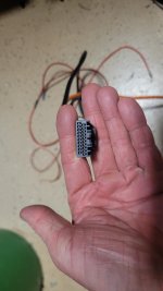
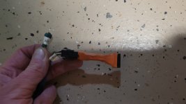
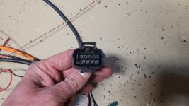
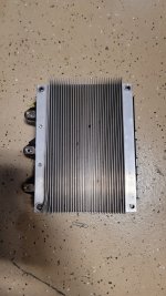
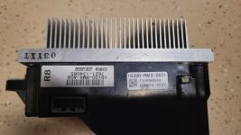
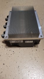
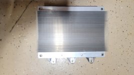
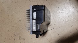
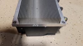
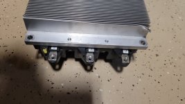
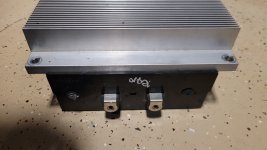
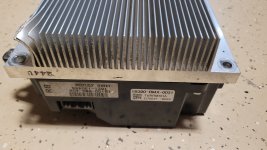
I have 2 Honda IMA inverters that I was using on a project. I am not using them anymore. One is brand new from Kiwifait and the other one was used in my gocart project a few years ago. I was going to use in my new gocart, but switched over to volt inverter for higher voltage.

One has the reverse broken because I hooked 12V up to the lodgic signal and the other one is brand new. It also has some dented fins on it because I rolled the go cart (no video to prove it happened) They both work just fine (except for the reverse function on the one). Power and regen work on both just fine.

The one with broken reverse is 650, the one that is brand new is 1000.

If interested let me know.

You can see them working in vids about 3 years old on youtube. My youtube name is Eric.Ensley1@gmail.com

Thank you
Eric
 
Last edited:
Here are some pics of the inverters. The one with the bent fins is the one with the broken reverse.

The one with the perfect fins is brand new from Kiwifait
 

Attachments

  • 20240324_140650.jpg
    20240324_140650.jpg
    1.4 MB · Views: 3
  • 20240324_140808.jpg
    20240324_140808.jpg
    2.3 MB · Views: 3
  • 20240324_140758.jpg
    20240324_140758.jpg
    1.4 MB · Views: 3
  • 20240324_140748.jpg
    20240324_140748.jpg
    817.3 KB · Views: 3
  • 20240324_140727.jpg
    20240324_140727.jpg
    2.4 MB · Views: 4
  • 20240324_140710.jpg
    20240324_140710.jpg
    1.1 MB · Views: 3
  • 20240324_140703.jpg
    20240324_140703.jpg
    1.3 MB · Views: 3
  • 20240324_140700.jpg
    20240324_140700.jpg
    1.3 MB · Views: 3
  • 20240324_140656.jpg
    20240324_140656.jpg
    2.6 MB · Views: 3
I was running the IMA at about 160V for a while, then I bumped it up to 200V for a bit more speed and power :)

The lebowski brain is AMAZING. The feild weakening is AMAZING!!!! With FW turned off the motor would accelerate like a rocket, and then hit a wall at about 5000RPM (due to the low 32Kv), but with FW the motor just kept going and going. I could get the motor to 5200 RPM under no load with no FW and 11,000 RPM with FW. The motor I was running was the hyundai HSG and it is a high inductance motor, and hard to control, but Kiwifait was able to get it dialed in and it was amazing!!!
 
I couldn't tell from the images: what external connections are there to the brain boards for programming and configuration on whatever setup the new user will have?

Is there any window/etc to see the LEDs for error / condition codes?


On the ones I was building here:
I was going to have either a connector at the IMA housing or a wire with connector fed thru the housing; though I didn't get far enough to decide that.

I was going to make a short fiberoptic path to the outside of the housing for the LEDs.
 
Amber,

Yeah, I forgot to put the pics of the wiring loom. Has a reset button, setup button. 12V power line (power on), Throttle input wires. The way you program it is with TTL thru the USB. I can take the housing off and power it up with 12V and you can see the LED's on the board. I can take the box apart to see the LED's if you want. Kiwifait yelled at me the one time I did that ( I was having issues and I thought the board could be bad, but it was the setting) because he was afraid I was going to screw something up. You can kinda sorta, not really see one or 2 LED's thru the connector opening, but all you can see is the light... barely.... But other than that it is really impossible to see the lebowski board.

But if you have questions let me know.

Sset up for resolver just like there is on the back of the HSG.

Eric
 

Attachments

  • 20240324_222126.jpg
    20240324_222126.jpg
    1.3 MB · Views: 3
  • 20240324_222152.jpg
    20240324_222152.jpg
    2.1 MB · Views: 3
  • 20240324_222155.jpg
    20240324_222155.jpg
    2.7 MB · Views: 3
  • 20240324_222238.jpg
    20240324_222238.jpg
    2.5 MB · Views: 3
  • 20240324_222302.jpg
    20240324_222302.jpg
    2.4 MB · Views: 3
  • 20240324_222325.jpg
    20240324_222325.jpg
    2.1 MB · Views: 3
  • 20240324_222352.jpg
    20240324_222352.jpg
    2.1 MB · Views: 3
  • 20240324_222403.jpg
    20240324_222403.jpg
    2 MB · Views: 3
  • 20240324_222410.jpg
    20240324_222410.jpg
    2.3 MB · Views: 3
Yeah, I forgot to put the pics of the wiring loom. Has a reset button, setup button. 12V power line (power on), Throttle input wires. The way you program it is with TTL thru the USB.

Does it have a 12V DC-DC inside the housing, or does the system you've built require an external one?

Mine was to have a single external one running both IMAs, bolted to the mounting frame between the IMAs (see the pic below for that frame).

I can take the housing off and power it up with 12V and you can see the LED's on the board. I can take the box apart to see the LED's if you want.
No, I was just curious how you set yours up; I think it was Kiwifiat that suggested the fiberoptic stuff to me, since I wanted to be able to see the status LEDs even with the units mounted under my trike, with their housings pointed up against bottom of the trike's cargo deck (sorry I don't have a pic of the FO stuff, as I never got that far):

1711339580390.png
 
Last edited:
No the IMA does not have a DCDC inside it. I was running 18V drill batteries with a DCDC step down to get to 12V and would just discharge the battery over time. I was using contactors out of a CMAX (if you need any contactors I have plenty).
 
Back
Top