3s3p Ridgid 18v Battery Packs for an E-Pocket Bike…safe?

Michael86

10 µW
Joined
Jan 8, 2024
Messages
5
Location
Ottawa
Hello,

I’m working on converting my 49cc Pocket Bike to Electric but want to ensure that I do it safely and am hoping for some help. The key area that I need help finalizing is the power source which I want to use Ridgid 18V 4Ah batteries (x9). The rational for this is that I have lots of these laying around already and therefore do not need to purchase any additional batteries – plus, when not in use for the bike they will be in use for my power tools.

Motor:
Vevor kit
Model: MY1020D
Input Voltage: 48v
Rated Current: 33A
Input Power: 1800 watts (at 54 Volts and 33 Amps)
Rated Speed: 4500 rpm
Max Speed: 5200 rpm


Controller Specs:
Model: BY15WF01-A
Current: 33A
Phase Degree: 120°
Conversion Efficiency: 90%
Low Voltage Protection Shutoff: 41±0.5V


Batteries:
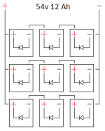
Would like to use 9x Ridgid 18v 4aH batteries 3S3P configuration for a total of 54v 12Ah (648wH) which equates to about 22 minutes at full rated power. I am also considering only running 6 batteries which would give me 54v 8Ah (432wH) which equates to about 14 minutes. I doubt I’ll be at full power for more than a few seconds ever. So I imagine 6 would be more than enough but have no problem fitting the full 9. Another reason to use these is I know they are high quality lithium cells compared to buying a battery pack off Amazon or Ebay. The 4Ah Ridgid batteries contain either Samsung 20R, Eve 20P or Lishen LR1865LA cells in 5s2p configurations. So the total current of each pack varies from 40-60 amps, less than the output required.


My questions here pertain to safety as I’m not expecting tons of range on this thing nor do I need it. It will be used in parking lots only when I’m at racetracks. So I’m never a far walk from the car.

Wire Sizing Note: I’ll be using a 35A fuse (Max 40A) and 8AWG wire on the positive terminal line to limit overall circuit amperage to the controller. I’ll run 12 gauge wire on each of the series runs with a 20A fuse on each of those legs. Expecting 11A per leg (33A rated/3 parallel legs).

General Comment on 54v: Fully charged batteries will be approx. 20.5v so about 61.5v. I’ve heard that some of the caps inside the controller might be 63v caps. That being said, I’ve seen lots of videos of people using larger capacity batteries with that controller with no issues. Vevor also states that the motor can run on 45-54v batteries. Also batteries will always be at the same state of charge when starting out.

Safety Question 1: Diodes and BMS

The specific packs that I plan on using are Ridgid which have BMS systems completely within the battery pack. From research they provide the low voltage protection so I don’t need to worry about incorporating that. What I have found online is mention of protecting the BMS from other packs when one shuts off. Sounds like a Schottkey Diode is needed for each pack. The one suggested online is discontinued now. onsemi 600V 50A, Rectifier Diode, 2-Pin TO-247 RHRG5060. I’ve found another one that I believe is sufficient

ST40250 (250v, 40A)
https://www.digikey.ca/en/products/detail/smc-diode-solutions/ST40250/21705610

Any thoughts or comments on this? Did I spec the diode correctly? I went for a cheap option which has an amperage and voltage sufficient to the application. Also…what does the diode do exactly in this case?


Safety Question 2: BMS shutdown….now what.

So….when a BMS is activated…it sounds like voltage continues to flow but just not threw that pack? Or does it completely disable that Parallel chain? If it still allows the other two packs in that chain to provide power then I would have 2 sets with 54v and the remaining leg would only be providing 36v. What happens in this case?

1704743804427.png

Non Safety Question…
Any recommendations on Sprocket Sizing? The rear tire diameter is only 10.8inches. Stock setup was a 6T front sprocket and a 68T rear. But that is an 11.33:1 ratio which shows a top speed of 12.8 MPH. From what I’ve seen online it appears that I should gear it for roughly 33.04 mph top speed. I don’t want to overload motor and will use throttle to ensure I keep my speed in check.


Final Comment:
Please point out safety concerns with this setup (other than a pocket bike with a 2.5hp motor)! I want to ensure that this is safe in terms of the batteries. Lithium Battery’s on fire really suck… with the BMS I don’t imagine I’ll have that much of an issue but I also don’t want to blow my battery packs.


Thanks!
 

Attachments

  • 1704743742787.png
    1704743742787.png
    4.2 KB · Views: 0
Last edited:
To keep it more readable, I'll reply in separate posts for different points:

When a normal BMS shuts off, it's output is disconnected. So if you have packs in series that have BMS in them like this, current no longer flows thru any of the ones in series.

If you have a setup where a bypass exists on a series set so that current will continue to flow and voltage across the shutoff BMS wont' blow it's FETS (from a voltage higher than it was designed to handle, that of just it's own pack), that series set becomes lower in voltage by whatever the shutoff pack was.

If you then also have other series sets in parallel with them, and those *don't* shutoff, then tehy're higher voltage than this series set, and none of the ones in it will contribute current anymore. (the diodes *should* prevent backflow of current from those still active into these inactive ones, but you should probably verify that in the actual setup)

So a shutdown pack in any series set will effectively disconnect that set from contributing anything to the system, when the above events occur.

That means you lose all current from them, so all the load is now placed across the remaining sets. So you should make sure that your system can correctly operate from just those (or even from just one) without overloading them.

I don't know if your packs' BMSes are of this type, or if they simply tell the tool to stop operating. That's something you'd have to check.


BTW, it would be easier to read your post if you didn't change the font size down from the default. If it's too large on your screen, I recommend using the Ctrl+ / Ctrl- keys on your keyboard, or the zoom controlls in the browser, to reduce the size of everything on your screen for this site. ;) (I have to do the reverse of this to read the already-small print on many sites).
 
Wire Sizing Note: I’ll be using a 35A fuse (Max 40A) and 8AWG wire on the positive terminal line to limit overall circuit amperage to the controller.

A fuse does not limit current to anything (other that all, or nothing). All it does is fail open when it's ratings are exceeded by enough for enough time. You have to check the manufacturer data sheet for the specific fuse you are using to know how long it has to exceed whatever current before it opens. (same for circuit breakers).

You want the fuse to blow before anything in the system can fail, so it has to be rated less (per those datasheets) than the least capable part of the series wiring/parts of that section of the system or else that other part will fail first before the fuse does in the event of current exceeding the part's capabilities.


The controller itself is what limits current in your system, to a max of whatever the Battery Current Limit is stated on it, plus or minus some amount depending on how well they actually designed and built it (they may or may not list that amount on it).

If you need that to be less, you have to change the controller's current limit. If it isn't programmable, you would have to change the physical current shunt in some way to increase it's resistance proportionally to the amount you want to change the limit, or change the circuit from the shunt to the MCU that lets teh MCU read that current.
 
General Comment on 54v: Fully charged batteries will be approx. 20.5v so about 61.5v. I’ve heard that some of the caps inside the controller might be 63v caps. That being said, I’ve seen lots of videos of people using larger capacity batteries with that controller with no issues. Vevor also states that the motor can run on 45-54v batteries. Also batteries will always be at the same state of charge when starting out.


Larger capacity makes no difference to voltage ratings. Capacity in Wh or Ah is just how long power will be supplied.

If you want to exceed the voltage rating of a controller (or whatever) you should check inside it for the voltage ratings of everything connected between B+ and B-. That includes the FETs, many of the capacitors (not just the can style), and the LVPS that converts battery voltage to 5v, 12v, etc.

While it's likely that they will all handle the voltage, there's no guarantee, as they'll usually use the cheapest parts avialable that will (barely) meet the advertised abilities of the controller (and sometimes, they fudge those higher than it can *actually* do, so exceeding them can result in POOF).

Also, VEVOR doesn't manufacture anything, they just slap their name on the stuff they resell, and the actual items provided are not always identical, so what you read about them might not apply to your specific parts...and since they all look about the same on the outside, you can't really tell unless you can see the insides of theirs to compare to yours, and even then there can be component differences. This is very very common with "brands". :(
 
Any recommendations on Sprocket Sizing? The rear tire diameter is only 10.8inches. Stock setup was a 6T front sprocket and a 68T rear. But that is an 11.33:1 ratio which shows a top speed of 12.8 MPH. From what I’ve seen online it appears that I should gear it for roughly 33.04 mph top speed. I don’t want to overload motor and will use throttle to ensure I keep my speed in check.
What you *should* gear it for is what you want out of it. ;)

If you're never going to use it for a high speed, gear it for something a little above what you want it to do, and then you have a lot of torque available and will load the motor less to do the same kind of startup, etc.

If possible, change the motor sprocket to be larger; it will be quieter with less chain and sprocket wear and more tooth engagement for higher torque capability.
 
Thanks for the responses!

Gear Sizing: The pocket bike had 6T but I forgot to mention that the VEVOR kit comes with a 9T - Its a larger size chain so I'll work on finding a suitable rear sprocket and new chain. Good point on the gearing. I'd like to try popping some wheelies so I'll get some more torque out of it.

BMS:

For the fuses I should have said - to protect the wire - not the controller. That being said you've brought up a good point. If the BMS shuts off the entire leg and goes down to only 1 leg then it would pull all the current from one leg. My idea for using the 12g wire with 20 amp fuses (standard Automotive blow fuses) is to physically prevent the bike from being able to operate on one leg so I don't have to use larger gauge wire everywhere.

Now for testing the BMS....I plan on taking one of the batteries and using wires to connect them to a power tool and then run that into the BMS kicks in for low voltage. If my wire voltage goes to zero then I should be good to go right? I assume that if it goes to zero that there is no need to test it in series with a second or third pack? Or is that something I should still look into? If it cuts it completely then I assume I don't need the external diodes?

If anyone has time to look at the site below it has two teardowns with lots of images with discussion on Ridgid BMS's. The second pack is newer but a smaller battery. I am not home right now so can't open any of mine up for images. Not sure if the function of the BMS can even be understood without having it in person. Figured I'd link it incase you're able to decipher anything.

Rigid 18V Lithium Ion Tool Battery Teardowns

Too add to that, many people online state that Ridgid and Ryobi have the low voltage disconnects in the pack and therefore they have full disconnects. I assume that means it should stop all voltage / current flow and disable that leg - which is the preferred end result in my case.

Oh and sorry for the font issue! I had it typed out in my OneNote and copy pasted it. Looked fine on my end!

Thanks,
Michael
 
I think they would have to have what's called a physical contactor to really disconnect. Like a physical switch that physically breaks the connection and is moved by a magnet. Technically you could get arcing across a physical contactor too, but it's much more protection.

A small tool pack isn't likely to have one. Any disconnect functionality they have is generally something like a solid state MOSFET, which can be forced open with enough voltage:

Maybe 20V tool packs tend to be over-spec'ed with 60V max fets, at least. Since that's a common component limit
 
I've continued research into the pack BMS MOSFET's and they have the following:

IRFB7437


Now there are 2 inside each pack. From another site it sounds like one is most likely for charging while the other is for output voltage. The concerning point is that they have a Vdss = 40 VDC (Drain-to-source breakdown voltage) as Inanek was mentioning.

What is promising is that the same research showed that the voltage across the FET is not the input voltage and that when a pack shuts off the voltage across the FETs only went to 15v (for 2 packs in series - these were Ryobi packs though with a similar FET). I plan on testing first on a single pack and then pending results double and triple packs in series.

TEST 1/2:
Test 1 I'll monitor both FETs on a single battery to determine which one is the output pack and monitor the voltages. Once I know which voltage is the one to consider I hook 2 up in series and have a voltmeter on both packs output FET as I want to have both at a similar state of charge so don't know which one will "die" first.

TEST 3:
The third test...based on the findings of test 2. If the voltages are still well below 40vdc for Vdss then I'll test it out. The issue is that I don't have tons of power resistor options. So that test from fully charged would take just over 9 hours...factoring in the Voltage drop it'll take longer. I've heard that you shouldn't place packs with a different level of charge together...What would happen if I put 2 fully charged packs and one with only 1 bar left? It would be at a lower voltage but would deplete sooner and make the test more manageable. Thoughts?

Here are my calculations based on the power resistors I have. I'm spec'ing them to stay below their Wattage.

1705167381616.png
1705167398506.png
1705167411734.png
 
Update.

I've tested a pack by itself and determined which of the two Mosfets was responsible for the pack cutoff. Once I discovered that I added another pack in series (36v) and finally then with 2 other packs (54v). In order to reduce the testing time I first discharged all the packs and then charged them to equal voltages (approx 30 seconds a pack). Then connected them with the load tables above and waited.

During all of the tests the voltage across the Drain-Source pins of the Mosfet spiked at 15.3v no matter the overall pack voltages so I have no concern about the breakdown voltage of the fet.

Onto my next concern. When a single, or two packs go down in one series leg, voltage / current continue to flow. So when the first battery drops out the voltage goes from 54v down to 36v. From what I can see online and from what @amberwolf mentioned this in his post:
If you then also have other series sets in parallel with them, and those *don't* shutoff, then tehy're higher voltage than this series set, and none of the ones in it will contribute current anymore. (the diodes *should* prevent backflow of current from those still active into these inactive ones, but you should probably verify that in the actual setup)

I believe that a difference in 18volts will effectively stop drawing current / voltage and the two remaining legs will take all the amperage.

Question 1:
Can someone explain this? At what voltage difference do different batteries stop contributing current?

Using a parallel battery simulator I was able to simulate this. Just hoping someone has a dumbed down explanation.

1705690443671.png

During that same research I've come across a few posts (mostly from this forum) that state that also adding a diode in series to the ones across the individual packs is beneficial to ensure that the other batteries don't try to charge the lower voltage pack.

So instead of my previous diagram (original post) the new one would look like this:

1705690603982.png

The 3 diodes on each of the series legs have been added.

Question 2:
Based on the diagram above and the battery currents / voltages mentioned. Can someone help me spec the diodes? I'm hoping for ones that have low wattage output and cylindrical in shape like the 1N54XX series. Part 2 of Q2 - are 1N5408 diodes sufficient for protecting each battery.

Comment on my battery packs:
What's very interesting is that I have 3 different versions of the Ridgid 4Ah packs. They all use the same Mosfets but what is interesting is the the two newer ones already have a diode across the + / - terminals! It's a 1N5408.

1705690907681.png

I don't recognize the logo on it. But based on that diode are those packs sufficiently protected? Or should I still add another diode externally. If they are sufficiently protected I'll probably just make sure I only use the newer packs and add 3 diodes - one per series leg. If the diodes are not sufficient and another external one is needed then I would like to spec them to protect the new or old packs - I hope this makes sense.

Thanks,
 
Input Voltage: 48v
Rated Current: 33A
Output Power: 1800 watts (at 54 Volts and 33 Amps)
You mean input power. Output power would be in the 1200-1400W range for brushless, 1000-1200W for brushed. Some motors have better efficiency, but Unite motors aren't that.
 
Back
Top