6 FET Xie-Chang 116 controllers on low voltage

Jeremy Harris

100 MW
Joined
Oct 23, 2007
Messages
4,208
Location
Salisbury, UK
As this has come up a couple of times, I thought I'd sum up the mods needed to run the baby 6 FET 116 controllers on low voltages. I'm indebted to Stator for reverse engineering the wiring diagram, it helped a lot.

The photos show the mods on a new bare board (Keywin Ge will sell these if you ask). My application is for low power on electric boats, so I wanted to be able to get the controllers to work well on a 12V supply. With the mods shown, the maximum voltage is about 18V (any more risks blowing the FET gates) and the minimum voltage is about 9.35V (set by the lowest LVC programmable after the mods).

The first mod is to mod the power supply section. The stock controller has a power resistor (R1) to reduce the voltage to the 12V regulator, which needs to be removed and replaced with a shorting link. The 12V regulator (U2) needs to be removed and the input and output pads shorted. These two mods allow the full supply voltage to be applied to the 12V parts of the circuit.

4413487146_e53804d26a_b.jpg


The next mod is to change the LVC sense circuit, to lower the minimum limit from 20.1V (the lowest value that the "Parameter Designer" software allows). R10 is removed and replaced with a shorting link. This makes any value of LVC programmed to be about 46% of the set value, so a setting of 20.1V will really be 9.35V.

4401939240_18cefc4cd7_b.jpg


The FETs I'm using on this particular board (which is not the final high power unit) are IRLB3034s, which have a package current limit of 195A, a silicon limit of 343A and typical Rdson of 1.4mohm. The downside to this spec is that Vds is only 40V.

View attachment irlb3034pbf.pdf

I'm not sure that these mods will be of much interest to many, but I guess it adds to the knowledge base on here.

Jeremy
 
The R1 shorting trick should work for high voltages too if you use this part.

http://focus.ti.com/lit/ds/symlink/tl783.pdf

as a replacement for the LM317.

I'm gonna piggy back on your pictures Jeremy, thanks!
 
The only thing to look out for if swapping the 317 for a 783 is that you can get the regulator warm if you're running at high voltage. The 12V supply typically draws around 60mA, so at 100V the 783 would be dissipating just over 5 watts. Not really a problem, but enough to warm the heatsink up a bit and increase the Rdson of the FETs, if they are on the same mounting bar.

I think the best option for high voltage use would be to use a small switched mode regulator for the 12V supply, the problem being that there's not much room inside the tiny case to fit one.

Jeremy
 
Jermey,

Wonderful post and thanks for the details so far...

I don't meant to follow on your coat tails (it seem I can't help it though, if history is an indicator) but I have been researching alot about current limiting and how to incorporate it into PS without it already (some coupled feedback from PWM DC output stage to counteract the PFC)... but I saw this post (having just received what I had hoped would be a 6FET 116 but turned out to be a 846, still useful for my purposes) and had been considering an upgrade of sorts to my goped ESR 750 EX...

The idea is to take my 5330 (one of the 3 I've been lucky to obtain, would you have happened to find a suitable replacement motor yet - power range, build quality and price??? Please share any insight you may have, Im looking for more budget 2-5 kw inrunners of a low kV perhaps in the range of 135 - 235?) and run in wye mode to drive my GoPed.

Already have the mount built for the tower pro, awaiting my new drive sprocket... in wye mode it will do top speed of 25mph on 6S pack and in delta about 40-45. I have a setting for 750w too which adjusts the current limit dynamically based on 746 + watts of loss (mechanical, motor 20%, drivetrain, etc) / Pack Voltage = Current Limit. To me this keeps it at 1HP braking power (to the rear wheel)... a thought I only considered when I found out the aussie govt actually building a bike dyno to test rear wheel or driven wheel hp.

In eiither case... these mods will be invaluable for use on my goPed and save me a ton on the controller (used 9FET infineon, modded similar to yours).


As always, thanks for leading the way!
 
Jeremy Harris,

Removing the LM317 only gained a few volts.
The LM317 runs fine with only a 3 volt drop across Vin and Vout.

Of course ... for you those 3 volts may be important.

Just my $0.02

-K
 
Knuckles,

I'm running these controllers on 12.8V nominal (about 14.5V max), so I definitely needed to get rid of the LM317. That regulator stops regulating at around 15 to 16V input, from then on the 12V rail on the controller just tracks the supply but about 3 or 4V lower. The lower supply has the effect of reducing the effective gate drive to the FETs, so increasing their switching times. This increases their dissipation.

Removing the LM317 allows the FET drive circuit to always work OK, in fact it allows a little bit more initial drive current, due to the slightly higher voltage, which is actually a good thing if you want to push the maximum output current up.

Removing the LM317 also slightly reduces the quiescent current, but only by about 4 or 5 mA.

Jeremy
 
Just thought I'd add another snippet to the collective information pool. For another boat application, I've been asked to build a high current, low voltage, controller. The customer wanted it to be as small a package as possible, so I decided to see just how much current I could get a 6 FET controller to handle. Because this is low voltage (24V nominal) I picked these IRLB3034 FETs:View attachment irlb3034pbf.pdf

They have a nice low Rdson of typically 1.4mOhm and a junction to case thermal resistance of 0.4 deg C per watt. The package limited current rating is a nice 195A, so I'm not likely to fuse an internal chip connect with high peak current. Using nice, thin, mica insulators, I can get the case to heatsink thermal resistance down to around 0.5 deg C per watt. By using a nice thick alloy case I can get the heatsink thermal resistance down to around 2 deg C per watt, so I end up with a total of around 3 deg C per watt from junction to free air. In theory, this means that I can safely put around 80 amps continuously through these FETs, maybe more. On 24 volts, that makes this little baby credit card sized controller capable of around 2kW.

The next problem was how the heck do I get this tiny board to take 80 amps without fusing the tracks? As I'm using a new case, I was able to add stuff to the bottom of the PCB. I opted to use some 18g copper sheet, cut into 5mm wide strips and soldered vertically to the tracks. By leaving the FET leads long, I've been able to get a really good connection to the copper strips. By choosing to fit the leads to the underside of the PCB I've been able to get around the problem of the holes not being big enough for decent sized wire.

Here's a picture to show what I've done, as it might be of use to someone else:

4443257653_198bc45c62_o.jpg


Jeremy
 
Lookin sharp Jeremy. The 18ga strips seem to make a neat installation for better bussbars.
 
Thanks, I reckon it would be possible to get 16g copper strips in there without too much bother and the width could be increased up to about 8 to 10mm, as that's the length of FET leads that stick out through the board. My guess is that this would get the board up to handling well over 100A, although I doubt that the FETs would take that for long without cooking.

What's needed is an easy way to hook up really big FET packages, ones that have good junction to case thermal performance, then we could be looking at getting loads of power from these little baby controllers.

Jeremy
 
That would be cool...!

I think that would require either:

a.
Transitional board that would create a stackup between some really large fets and the controller board.
This is the most work, but would eventually be the easiest to connect up.
I envision a set of board stacking connectors between the two and would include phase wiring, gate wiring, and shunt wiring.
Its not too much. Therefore, it would be a simple board.

b.
A harness of wires to transfer gate drives, phase wires, and 4 terminal kelvin connected shunt wiring that is offloaded from the 6 fet board to a
large fet power board.

In both cases, I think that an aluminum based power board would give the excellent cooling.
The aluminum could be water cooled with the right case.

But, I'm amazed at what has been done in fiberglass
by all the manufacturers, Castle Creations, Turnigy, and XIECHANG even if I do poke fun at them. :mrgreen:

Eventually, it would be great to have an open source 6 fet including hardware and software. There are reference designs that are freely available from
several reputable electronics manufacturers that could be layed out and eliminate the need for a transition board.
The transition board would become a new controller.

I am amazed at the work done on the XIE change controllers regardless, almost open source. :)
 
One summer years ago I worked on the PCB design and prototype build of a 3phase 380V motor controller. This was used to turn a mixer paddle in a pulp processing plant. Think food processor, but 120m tall.

FETs were TO3 like in size but with spade connectors on the package. The power was off the PCB in separate buss bars.
 
Jag,

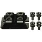
Were they a SOT-227 aka ISOTOP package?

sot227.jpg
 
12p3phPMDC said:
Jag,

Were they a SOT-227 aka ISOTOP package?

Not exactly. Similar idea but spade connectors on package instead of screw terminals.
Neither google nor the thick Newark catalog turned up a picture of it. (Google insisted I must have misspelled something in my image search for SOT FET and turned up a lot of scantily clad women instead of transistors)
 
Coming back to this later
 
Back
Top