ANT BMS wiring with Nucular P24F

Ziip0

1 mW
Joined
Oct 10, 2018
Messages
16
Hi, I would first like to explain to you that I know very little about electric bikes.

I bought a NYX bike a few years ago with an Adaptto controller installed on it, it also had an Adaptto BMS for battery protection. The controller broke down last year. I purchased a Nucular P24F to replace it.

The Adaptto BMS is unfortunately not compatible. So I also wanted to buy a Nucular BMS (because it's plug and play, easy like the Adaptto BMS), the team told me it would be available at the end of last year. Still no news today!

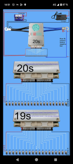
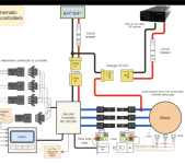
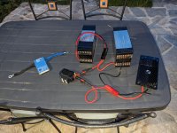
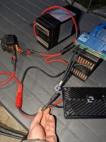
I ended up buying an ANT BMS 20s... In the meantime I redid all the wiring to pass the motor phases and HALLS through the inside of the bike... I made sure to connect a phase to the + of the charger as shown in the Nucular diagram...

Now I don't know how to connect the BMS, how to include it in the circuit! The ANT BMS diagram is classic, recharging does not go through one motor phase...

Please help me, I don't know what to do anymore. I would really like to have a wiring diagram for my situation.
 

Attachments

  • Screenshot_20240306-145102.png
    Screenshot_20240306-145102.png
    1.2 MB · Views: 7
  • Screenshot_20240306-223902.png
    Screenshot_20240306-223902.png
    450 KB · Views: 7
The BMS should go inside your battery, in the circuit it's essentially in the battery.
Charge current gets regulated by the controller, so only the controller and charger negative have to be connected to the BMS.
 
Last edited:
Yes ofc I know that, I just don't know how to correct wiring everything.

To begin I need to connect blue wires B- from the BMS to the first cell negative according to ant bms diagram. But in my case with nucular controller with + charger on motor phase, it's also what I need to do?

Then black wires C- from the BMS to negative controller and negative charger, also what I need to do in my case?

Little wires to each positive cells, no problem I understand. But the last little red wire where I should connect it? To + battery which also goes to + controller and not to + charger in my case? Or should I connect this little red wire to + charger which goes to motor phase?

It is that type of questions that I need to find correct answers :unsure:
 
The BMS should go inside your battery, in the circuit it's essentially in the battery.
Charge current gets regulated by the controller, so only the controller and charger negative have to be connected to the BMS.
Ok thanks to have edit your message, I get more infos.

So the only difference compared to ANT diagram is the + charger which needs to connect to motor phase and not to the + battery?

And for the little red wire, last positive cell like on the diagram or motor phase and + charger?
 
Here's my packs if that can help, 1s to 20s right to left.

So to begin I just need to connect black bms C- to negative controller and negative charger?
I don't have to use blue bms B-?
 

Attachments

  • PXL_20240307_182109973.jpg
    PXL_20240307_182109973.jpg
    2.7 MB · Views: 5
  • PXL_20240307_182204692.jpg
    PXL_20240307_182204692.jpg
    3.2 MB · Views: 5
You should connect your BMS first and have it work, then worry about the rest.
This means getting those 21 thin wires wired correctly, or you'll destroy the BMS.
The C- from the BMS then goes to the controller via the red Anderson plug and the charger- goes to the xt150 that is in your hand.
 
Good good I begin to see brighter, thanks to you.

- ok yes first I need to connect all the thin wires from 1s positive to last 20s positive. Also the thin red wire to 20s positive in my case?

- then I have to test if the tensions between the wires are ok and show me the correct total packs voltage.

- then I connect blue B- wires to the first negative cell, for that I delete the black negative wire which actually goes to the Anderson connector for the controller / charger negative

- then I can connect the connectors with the thin wires to the BMS, connector with thin black wire first, then with red

- then I power on the BMS with 3-5v battery

- then I can connect the C- wires to the Anderson connector instead of the actual black negative wire 8AWG

I am right ?
 
The thin black wire and the blue BMS B- goes on the Battery-
Before connecting the 2 balance plugs, measure all the voltages, keep the black voltmeter probe on the thin black wire. With the red probe you start with the pin next to the thin black one, it should be lets say 3.7v move the red probe to the next pin the voltage should be 7.4v and so on.

After that, start the BMS. I recommend disabling sleep mode.
Remove the 8AWG wire from the Battery- and connect it to C- on the BMS
 
All right! Thanks for these detailed explanations :)

What about the thin red wire? 20s positive according to the diagram? Or with + charger / motor phase?

I will never have the space to attach the big B- connector to the first negative cell. I'm thinking of leaving a piece of the 8awg to solder the wires to. In my place, what would you do?

Just like the 4 wires of the C- will never fit into a solder terminal of the Anderson connector, I am also thinking of soldering them to a piece of the 8AWG. Same, in my place what would you do?

I have a doubt about the cable sections, 4x12AWG is bigger than 8AWG
 
I have a doubt about the cable sections, 4x12AWG is bigger than 8AWG
That depends on how much current the controller draws, if the 8AWG doesn't get hot, then it's fine.

What about the thin red wire? 20s positive according to the diagram? Or with + charger / motor phase?
Connect it to B+ along with controller+

I will never have the space to attach the big B- connector to the first negative cell. I'm thinking of leaving a piece of the 8awg to solder the wires to. In my place, what would you do?

Just like the 4 wires of the C- will never fit into a solder terminal of the Anderson connector, I am also thinking of soldering them to a piece of the 8AWG. Same, in my place what would you do?
Unless you change all wires and use bigger connectors, your idea is the only realistic way of doing it.
 
Got it! Everything's clear now sir! Thank you so much for your help!

I've just ordered 120A Anderson connector instead of 50A that I have, terminals are bigger and will fit with 4 12AWG wires.

I will keep the 8AWG B- piece for soldering blue wires, no reason to get hot, I just thought that the batteries are still the same lol
 
Hello, I connected the bms, everything works fine, thank you again

I haven't dared to charge the batteries yet, I want to be sure that everything is properly configured before, I don't want to ruin all these hours of work for nothing...

I watched a video from Doctorbass
which explains how to configure the batteries I have (EIG C020B, 3.7v nominal / 20Ah / 100A nominal discharge, 200A peak ) with an Adaptto controller + Adaptto BMS to get an idea of the parameters I need to adjust in the ANT BMS app

Most of the parameters are different, I don't understand everything, far from it.

BMS SETUP

He explains
- 4.15v HV
- 3v LV
- 4.13v or 4.14v balancing
- 2.5v critical shutdown
- Battery 1480 wh
- Discharge cutoff 66v
- High voltage cutoff 83v
- Vsoft limit 000.8v

CHARGE SETTINGS

He explains according to the charger sold with it (EATON brand, 1000w, 48v output), I have this charger.

- supply current 20A
- charging current 15A
- supply Vdrop 1.19v
- ChgSensor inv : YES
Here's some screenshots of ant bms app, I already changed some parameters, but there are many parameters for which I cannot find an equivalent, notably for the number of 1480 wh, Vsoft limit, and the whole part concerning CHARGE SETTINGS. Please help me configure everything correctly, tell me what I can change, what values to put etc... in fonction of what Doctorbass said.
For example also, I don't understand RemainC which is set by default to 50ah, should I put 20ah as PysicalC?

I have 0.009v max dif, will the ant bms will be able to balance that ?
 

Attachments

  • Screenshot_20240310-200322.png
    Screenshot_20240310-200322.png
    122.5 KB · Views: 2
  • Screenshot_20240310-194548.png
    Screenshot_20240310-194548.png
    254 KB · Views: 2
  • Screenshot_20240310-194520.png
    Screenshot_20240310-194520.png
    228 KB · Views: 2
  • Screenshot_20240310-200108.png
    Screenshot_20240310-200108.png
    196 KB · Views: 3
  • Screenshot_20240310-200101.png
    Screenshot_20240310-200101.png
    243.4 KB · Views: 3
  • Screenshot_20240310-195504.png
    Screenshot_20240310-195504.png
    213.8 KB · Views: 3
Back
Top