As if I don't have enough projects: time for my first ebike build!

DIYer

1 mW
Joined
Sep 20, 2023
Messages
11
Location
VA
Hi all, I--like many of you, I'm sure--decided to add another new project to the queue. Though I have some electric motorcycle experience (I installed lithium modules into my Vectrix VX-1), this will be my first ebike build. The plan is to electrify a steel Trek hybrid. So far, I have collected the following parts:
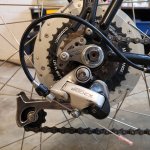
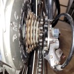
  • BMC Model 14110-2 (V2) 48V 600W rear hub motor with 700C wheel (used)
  • BMC 48251111 25A motor controller
  • BMC-compatible 48V thumb throttle
  • 48V 15AH battery packs from this thread
  • 54.6V OHRIJA smart charger (output reduced from 5A to 4A for use with the batteries above)
  • Miscellaneous JST and bullet connectors
Once I have the throttle, I think I'll have what I need to bench test my setup. Still unsure whether a Cycle Analyst is mandatory in this usage case. Otherwise, the motor is the biggest uncertainty as I picked it up cheap from an online auction and have yet to see it function. It had apparently been used for a college recumbent bike project. Someone JB Welded a piece of metal onto one side of the clutch, presumably to enable both forward and reverse functionality for the recumbent bike 🤷‍♂️ Unfortunately, after torching off the JB Weld, the clutch still won't spin freely in either direction. I understand that MAC clutches are compatible, but I'm having trouble finding a cheap, used one.

20230920_145851.jpg 20231029_142839.jpg

Another unfortunate thing about this project (or any using older parts) is that a lot of information is no longer accessible. Lots of relevant old ES posts point to the now-defunct http://www.ebikesf.com/ website, and lots of the pictures are missing even when using the Wayback Machine on archive.org.

Any chance someone has the BMC throttle pinout or any information about the brake cutoff switch for the controller? Any other documentation for the motor throttle controller would also be a huge help!
 
Did they get JBWeld down into the clutch roller slots? (under the plate) If so, they'd need to be cleaned out so the rollers can move against their springs back up the ramps to allow freewheeling.

Otherwise, you can still use the motor as-is, it just won't freewheel when not under motor power. There are two ways to deal with that resistance; you can use a CA to adjust the throttle voltage to the controller to always have a tiny amount of "freewheeling". current, or you can use a potentiometer in the throttle ground to "lift" the throttle voltage up a little bit to do something similar, adjusting the pot until the motor doesn't spin on it's own but has less resistance when just pedalling.

What functions would you require the CA to do for your system? (with no info on what the system is intended to do for you or what conditions it has to do that job under, I couldn't say if it is needed or not).

I don't know the BMC controller wiring, but it is not usually too tough to figure them out. What groups of wires does it have for each connector?
 
After some additional messing around with it, I was able to free up the clutch! Must have been some remaining bits of JB Weld holding things together.

Honestly, I'm going for as simple a system as possible. The throttle has three voltage indicator lights, so I was mostly unsure if the CA would otherwise be needed. As far as overall usage, I do have some fairly steep hills around me, but the setup will mostly be for easy, flat rides and running errands with a svelte rider.

The connectors on the BMC model 48251111 (48V/25A) motor controller are straightforward. I expect everything should be pretty plug-and-play. The only ones I'm not sure how to connect are the red, blue, and green brake cutoff wires.
  • Phase wires (bullet connectors)
  • Discharge wires (Deans connector)
  • Hall Sensor (5 pin female JST)
  • Throttle (4 pin male JST)
  • Brake cutoff (3 pin male JST)

20231029_204828.jpg
 
Last edited:
I used Lyens gears on my v1 bmc, dont know if he sold a complete unit or clutch, 5-8 yrs ago now.
All my throttles from greentime evfitting aliexpress, thumb 3 wire, I buy cont from same place, they got spokes to so that might help you out to take a look at the site. I try to pick e-packet shipping for quicker shipping from the usuals.
 
After some additional messing around with it, I was able to free up the clutch! Must have been some remaining bits of JB Weld holding things together.

Honestly, I'm going for as simple a system as possible. The throttle has three voltage indicator lights, so I was mostly unsure if the CA would otherwise be needed. As far as overall usage, I do have some fairly steep hills around me, but the setup will mostly be for easy, flat rides and running errands with a svelte rider.

The connectors on the BMC model 48251111 (48V/25A) motor controller are straightforward. I expect everything should be pretty plug-and-play. The only ones I'm not sure how to connect are the red, blue, and green brake cutoff wires.
  • Phase wires (bullet connectors)
  • Discharge wires (Deans connector)
  • Hall Sensor (5 pin female JST)
  • Throttle (4 pin male JST)
  • Brake cutoff (3 pin male JST)

View attachment 342138
Is there a reason for needing the cutoffs when using a throttle only system?
 
If you require them for some reason (since you don't have PAS the motor won't run on after you let off the throttle, and you can't do regen with the clutch freewheeling in the motor):

Brake cutoffs are normally two wire, as they are typically just a switch connecting brake input to ground.

While it's not very common some do exist that use three wires (that aren't variable regen like some FOC controllers). The only controller I have had with three wire brake connectors used digital hall sensors (just like in the motor) for the control signal in the lever, which is powered by 5v, and the hall signal has a 5v pullup resistor inside the controller (just like the motor halls), and the signal itself is open circuit when the hall is inactive (lever not pulled) and grounded when it is active (lever pulled). (the hall in these levers is inside a switch body taht looks like a normal pushbutton momentary, placed where one of those would be in the lever).

But both kinds of switches do the same job--grounding the brake signal, so the only wires you *have* to use are the ground and the signal, if using a passive switch.

If not using ebrake levers, just leave them unconnected.


FWIW, a four wire throttle usually has 5v, ground, throttle signal, and battery voltage. Should be easy to tell which is which with the controller plugged into the battery and turned on, no throttle plugged in. If you find ohter voltages there than those, you may want to open the controller to see which is wired to which pads. Sometiems the pad names help determine what the wires are for.


If you want as simple a system as possible, leave off the ebrake levers and don't use a CA.

The CA has many functions, not just displaying battery voltage or monitoring capacity / power usage / etc., so to find out if you need any of them, you should to define for yourself a list of exactly what you want from the system in detail, then see if any of the things you want can't be done with the system you have, *and* that it can be done by the CA.

But basically, if you can't think of anything, during a ride, that you wish the system did that it doesn't, you don't need a CA or anything else for it. ;)
 
Thank you for the very helpful context! And given your points, I think I will hold off on adding a CA.

One thing that most ebike wiring diagrams don't seem to include is a fuse. And because my controller doesn't have an ignition switch connector like newer controllers, I figure I will add a switch and fuse on the positive wire between the battery and controller.
 
Fusing is not usually in the diagrams because it's kind of complicated. (and batteries may already have one built in)

It depends on what you want the fuse to protect, first, and how much current it will take to damage it.

Then it depends on what kind of current the system will require, worst case, and for how long.

Then you find a fuse whose datasheet time/current curve chart from it's manufacturer shows that it will not trip/blow at the current the system requires, regardless of the amount of time, but that it *will* trip blow "instantly" below the current that will damage the thing you want the fuse to protect.

Then you install the fuse between the battery (or current source) and the beginning of the thing you want the fuse to protect.
 
Last edited:
According to the seller's description for my battery packs ([$89 plus shipping. USA BASED] 48v 15ah 720wh 60A Li-Ion Battery, 2500 mAh cells, 13s6p configuration), the packs have a discharge rate of 60A continuous or 90A peak (720W continuous or 1400w peak). To me, it seems the 25A-output motor controller would be the weaker component to protect, but I can't find and specs for this BMC controller.
Everything in the circuit, wiring, connectors, electronics, etc., should be protected.

The battery itself probably has a BMS similar to it's larger cousin in that seller's other thread, like this image from it, showing the built-in white and gold 40A fuse in hte positive discharge line at the lower right, and the smaller fuse in the charge line near the middle:
1698983082722.png
So the pack itself, and it's BMS, are internally protected, and don't need an external fuse.

Which parts you're choosing to protect with a particular fuse will determine what fuse you use and where you put it.

If the controller outputs 25A (phase current) then it's battery current input draw is probably much less than that, less than half. If 25A is the battery current (input) then that's the continuous (probably) current it could draw from the battery under full motor load, but it might have short peak currents that are higher. (if you have a wattmeter, you can measure this on a ride with the worst-case riding conditions and terrain, otherwise you can guesstimate it might be 50% higher peaks for up to a few seconds.)

I don't know waht your connectors and wiring between battery and controller are rated for; but if there was a short between them at say, the controller input, the fuse inside the BMS would blow, cutting current off. (same thing if the FETs in the controller failed shorted across the battery + and -.
 
Successful first bench test! Happy to see the used motor is functional, especially after having to undo the clutch modification.

20231106_204157.jpg
 
DIY ebike achievement unlocked! Scrounged up a 7-speed freewheel and replacement M14-1.50 axle nut and was finally able to mount to my 1992 Trek 720 Multitrack. In my initial tests, top speed appears to be about 25mph. 3D printed a custom controller mount, and custom rack battery mounts are on the printer now. Thinking about using an NTE R185 circuit breaker as my ignition switch/ power switch. And in an attempt to improve safety, I'll be replacing the very old Shimano brake pads with Kool Stop Eagle Claw 2 pads.

20231119_163834.jpg
20231119_002333.jpg
20231119_002346.jpg
20231119_002316.jpg

20231119_002440.jpg
 
Torque arm installed. Had to do a tiny bit of filing to clear the rear derraileur arm, despite all the different angles the Grin V5 can mount.
 

Attachments

  • 20231201_210829.jpg
    20231201_210829.jpg
    1.6 MB · Views: 5
  • 20231201_210849.jpg
    20231201_210849.jpg
    1.4 MB · Views: 5
Last edited:
Back
Top